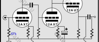
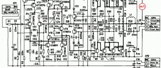
Schematic diagram of a homemade hybrid power amplifier (UMPA) by Jeff Macaulay using a lamp and field-effect transistors.
Jeff Macaulay, when developing a hybrid UMZCH, was guided by the fact that tube amplifiers usually sound better than transistor amplifiers at mid frequencies, but are inferior in detail and energy at the edges of the audio range.
The described amplifier provides 80 W into an 8-ohm load with a harmonic distortion Kr<0.04% (1 kHz), a bandwidth of 5 Hz - 35 kHz (20 W, -3 dB) and a signal-to-noise ratio of more than 100 dB.
The only voltage amplification stage is made on a bipolar transistor Q1 2SC2547E with a dynamic load (SRPP) on a VI ECC88 triode.
Note. The use of a transistor provided a significantly higher (by about an order of magnitude) gain of the cascade than that of a vacuum triode, and the dynamic load ensured almost “tube” linearity.
Schematic diagram
One half of the ECC88 (E88CC) contains a tube buffer circuit, also known as a Cathode Follower. The tube buffer does not have voltage gain, but has current and power gain.
In audio electronics this is often used when the amplifier has sufficient gain but still requires volume control with a low output impedance.
Such a tube buffer has a very low coefficient of nonlinear distortion and, when paired with an UMZCH on microcircuits, produces a very pleasant sound.
The author writes that, according to his personal perception, UMZCHs on microcircuits in combination with a tube buffer make music more balanced, natural, and give it a pleasant sound, which differs from the sound of amplifiers without installing cathode followers.
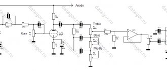
The LM3875 chip is used to assemble an audio power amplifier capable of providing output power of up to 15W into an 8-ohm load and up to 30W into a 4-ohm load.
The author also decided to make a delay system for connecting speakers; it is made using transistor Q1. This part of the circuit is used for two channels, closing the RLY1 contacts in each of the channels a few seconds after turning on the power.
Rice. 1. Schematic diagram of a hybrid audio power amplifier based on a 6N23P lamp (ECC88) and an LM3875 microcircuit.
In the power supply, the author used a 180W toroidal transformer with eight 12V secondary windings.
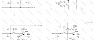
Rice. 2. Schematic diagram of a power supply for a hybrid power amplifier using tubes and microcircuits.
HYBRID ULF
At numerous requests from radio amateurs, I present an improved and more complete diagram of a hybrid ULF with a detailed description, a list of parts and a power supply diagram. The lamp at the input of the 6N6P hybrid ULF circuit was replaced with a 6N2P. You can also install the 6N23P, which is more common in old lamps, in this unit. Field-effect transistors are replaceable with other similar ones - with an insulated gate and a drain current of 5A and higher. Variable R1 - 50 kOhm is a high-quality variable resistor for the volume control. You can set it up to 300 kOhm, nothing will worsen. Be sure to check the regulator for the absence of rustles and unpleasant friction during rotation. Ideally, you should use ALPS RG - this is a Japanese company producing high-quality regulators. Don't forget about the balance regulator.Trimmer resistor R5 - 33 kOhm inserts zero voltage on the speaker in the ULF silent mode. In other words, by applying power to the transistors and instead of a speaker (!), connecting a powerful 4-8 Ohm 15 watt resistor, we achieve zero voltage on it. We measure with a sensitive voltmeter, since it should be absolute zero. The diagram of one hybrid ULF channel is shown below.
The remaining resistors are 0.125 or 0.25 watts. In short, any small ones. A 10,000 µF capacitor can be safely reduced to 100 µF, but it is drawn according to the old designation. We set all capacitors for anad supply to 350V. If it’s difficult to get 6.8 μF, set it to at least 1 μF (that’s what I did). We will replace the quiescent current control transistor with KT815 or KT817. This will not affect the sound, it simply corrects the current there. Naturally, we need another copy of the hybrid ULF for the second channel.
To power the transistors, you need a bipolar source of +-20 (35) V with a current of 4A. You can use a regular transformer. Since more power was not required, I installed a 60-watt trans from a VCR with a corresponding reduction in output power. Filtration is simple - a diode bridge and a capacitor. With a quiescent current of 0.5A, a capacity of 10,000 microfarads per channel is sufficient. Capacitors C3, C4, C5 160V each, no less. Or more just in case. R8 is a small tuning resistor - turned with a screwdriver. It sets the quiescent current of the output transistors (in the absence of a signal). You need to set the current from 0.3A - mode AB to 2A - mode A. In the second case, the sound quality is much better, but it will not heat up much. You can also use an electronic transformer for power supply with an additional ring and windings of 12 turns - it receives 12V from the transformer, and two 20V each - this is the secondary. In this case, the bridge diodes must be high-frequency; simple KD202 will burn out instantly.
We feed the filament with 12 volts by connecting the filaments of both lamps in series. I took the anode voltage of 300V using a small transformer (5 watts) from a Chinese multi-voltage adapter. You can't power anything from that parody except an LED, but in this hybrid ULF it comes in handy. We supply 12V to its 15-volt secondary from an electronic (or conventional) transformer, and remove the voltage from the 220-volt network. The current is certainly not that great, but both 6N2P lamps pull only 5mA across the anode, so they don’t need more. Hybrid ULF Forum
Forum for discussing the material HYBRID UNCH RADIO
CONTROLLED TRACTOR FROM A REGULAR TRACTOR
Converting a toy ordinary tractor into a radio-controlled one - photos of the process and the resulting result.
Provides basic information about planar fuses, including their technical characteristics and applications.
Review of a Chinese device for water electrolysis - photos, videos, description of work.MEMS MICROPHONES
MEMS microphones are a new quality in sound recording. Detailed description of the technology.
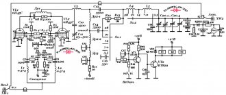
New type hybrid HF power amplifier
Radio amateurs using professional radio receivers experience difficulties in obtaining in the transmission path the power of several tens or hundreds of watts necessary for operation on the air, because The output power of a modified receiver or transceiver attachment for it, as a rule, does not exceed 2-3 watts. In this case, it is most advisable to use a hybrid power amplifier (PA), which allows you to obtain a power gain of up to several hundred.
Some radio amateurs are distrustful of hybrid RAs, believing that such amplifiers do not provide high-quality signals. In fact, hybrid RAs provide high-quality signals that are in no way inferior to amplifiers made using classical circuitry. It should be noted that hybrid amplifiers require careful adjustment and understanding of the processes that occur.
There are publications of hybrid RAs using both bipolar [1] and field-effect [2] transistors; unfortunately, both of them have disadvantages, which I will briefly discuss.
The main disadvantage of bipolar transistors is the need to set a large initial current of 100 mA or more to bring the transistor to the beginning of the linear section of the characteristic. A large initial current of the transistor and, accordingly, the lamp, reduces the efficiency of the amplifier and leads to overheating of the lamp anode even in the absence of an excitation signal. A small initial current leads to signal limitation from below and noticeable nonlinear distortions.
The disadvantage of field-effect transistors is the high residual voltage at the drain (8...12 V) and, accordingly, high internal resistance. The current of a field-effect transistor, for example KP901, begins to be limited at about 300 mA. Since after reaching the specified current, an increase in the excitation amplitude does not lead to an increase in the drain current, the signal is limited from above.
The proposed hybrid RA uses a bipolar transistor. The inherent disadvantages of this option are eliminated using special circuitry, which allows you to separately set the initial current of the lamp and transistor, for example: the lamp current is 15 mA, and the transistor current is 120 mA.
The amplifier operates two 6P45S tubes with a KT922B transistor in the cathode. Unlike known circuits, voltage from a current stabilizer made on transistors VT5 and VT6 is supplied to the collector of transistor VT4 through decoupling choke L7 and protective diode VD11. Through the transistor VT4 in the cathode of the lamps, the total current of the lamps VL1 and VL2 and the stabilizer on VT5 and VT6 flows. Each of these currents is independently adjustable and can be set to a given value, thereby ensuring the required operating mode for both the lamps and the transistor. The current passing through the lamps and transistor VT4, in the absence of excitation voltage, is the initial current of the lamps. When the excitation voltage is applied, the current through the lamps and transistor changes and is proportional to the excitation level. That part of the current that flows to transistor VT4 from the stabilizer is always constant and does not depend on the excitation level. A chain of two diodes VD7, VD8 and a zener diode VD6 protects the transistor VT4 from overvoltage. The filament voltage for the lamps is supplied through inductor L6, which eliminates the harmful influence of the capacitance between the cathode and the filament. The excitation voltage is supplied to the base of transistor VT4 through a broadband step-down transformer T1, which matches the 50-ohm PA input with the low-impedance input of the transistor. The ALC voltage is removed from the emitter of transistor VT4 and adjusted using potentiometer R25.
The node on the DD1 chip allows you to switch the PA to transmission mode. The control procedure is as follows: after closing the pedal contact to the body, the key on VT1 locks RX; after a given time interval, antenna relay K1 connects the antenna to the PA; and finally, after a time delay, the transmission mode is established using relay K2. After releasing the pedal, the process is reversed: TX is turned off; The antenna switches and the receiver is allowed to operate.
Establishing RA
begins with setting a current of 100-110 mA in the current stabilizer at VT5, VT6. To adjust the stabilizer, it is necessary to disconnect the collector of the VT5 transistor from the rest of the circuit and connect it through a milliammeter and a 300 Ohm resistor connected in series with it to the housing. The stabilizer current is set by resistor R27, the value of which is determined by the formula R = 0.625 / I, where the resistance is in Ohms, the current is in Amperes. In our case, a 6.25 Ohm resistor is required. There is no standard resistor of this value, so you should connect two resistors 6.8 Ohm and 68...82 Ohm in parallel. Next, after restoring the current stabilizer circuit, by adjusting potentiometer R14, the initial lamp current is set to 15...20 mA (PA - in transmission mode, excitation is not applied). If the initial current does not fall within the specified limits, it is necessary to change the value of resistor R11. The total current through transistor VT4 must be equal to the sum of the currents through the lamps and the current stabilizer. The base current of transistor VT4 is small and may not be taken into account. Current control VT4 is carried out by the voltage drop across resistor R20.
The last stage is setting up the PA contour system. The starting point for tuning is the anode current of the lamps with excitation applied and the anode circuit detuned.
When adjusting the excitation level, it is necessary to set the anode current of the lamps, with a detuned circuit - 620 mA. This operation must be performed very quickly, because... in this case, all the supplied power is dissipated on the anodes of the lamps, and they may fail. Now, by adjusting the antenna capacitor and adjusting the anode capacitor of the loop system, until the anode current declines, set the latter at 550...560 mA. The decay of the anode current at resonance, in relation to the “drive” current, should be 10%; it is this value of the decline of the anode current that ensures good linearity and high efficiency of the RA in SSB mode. In the CW mode, the decline in the anode current can be 20%, in this case the maximum PA power is achieved and the thermal conditions of the lamps are facilitated. It should be especially emphasized that when setting up the anode circuit, the excitation signal must be either single-tone or CW. The use of a two-tone signal or voice when setting up the PA, as well as the use of various field strength indicators, does not allow the amplifier to be properly configured and leads to the appearance of intermodulation distortion and, as a consequence, to an expansion of the emitted frequency band.
The proposed amplifier, with a high-quality circuit system, provides a peak power in SSB mode of 385 watts, with an efficiency of 68%, and the level of intermodulation distortion does not exceed -30 dB. The input voltage required to achieve maximum power does not exceed 10 V into a 50 Ohm load.
A few general notes
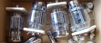
. 6P45S lamps have anodes located not quite symmetrically relative to the grids, which leads to uneven heating of the anode and a decrease in the power dissipated by it. Therefore, maximum RA power can be provided only by specially selected lamps with uniform heating of the anode.
In the 6P45S lamp, the conductor connecting the anode to the anode cap inside the lamp is made of thin copper wire, which can melt when the RA operates with maximum power at the highest frequencies. Therefore, when operating on the 24 and 28 MHz bands, it is necessary to reduce the PA output power by 30%.
An amplifier using 6P45S lamps requires a fairly low load resistance and a correspondingly large variable anode capacitor. Since such capacitors are currently in very short supply, it makes sense to replace it with a set of constant capacitors, switched by a range switch. In this case, a ball variometer can be used as a loop inductance; it is also used to tune the anode circuit to resonance.
The proposed version of the loop system has a narrower range of matched resistances than in a conventional P. loop and requires the use of antennas with cable reduction.
And finally, about some design features of the RA.
The amplifier tubes are installed along the rear wall of the chassis at a short distance from it. The finned radiator (150x40 mm), on which the VT4 is installed, is mounted on racks 3 mm high on the outside of the rear wall of the chassis, with the fins facing outward. The terminals of the VT4 transistor, passed through the hole in the rear wall, are located next to the terminals of the cathodes of the lamps, so that the distance from each cathode to the VT4 collector is the same. Anti-parasitic chokes connecting the anodes of the lamps to the separating capacitor C19 must also have the same length.
Two holes with a diameter of 58 mm are cut into the chassis for installing lamps. Two lamp sockets are mounted on an aluminum plate located under the chassis so that the lamps are recessed by 18 mm after installation. The T5 transistor is installed on a 40x40 mm needle radiator.
It is recommended to lay a common body bus made of thin copper or foil PCB with a width of 15...20 mm between the body part of the antenna connector and the lamp sockets. All blocking capacitors connected to the lamps, as well as all parts of the circuit system that must be connected to the housing, must be connected to the housing bus. There is no need to isolate the chassis bus from the chassis.
Literature:
1. Zhalnerauskas V. Hybrid linear power amplifier. “Radio” No. 4 1968 2. Andryushchenko B. HF amplifier “Retro”. “Radiomir HF and VHF” No. 4 2002