The operation of electrical and electronic devices occurs due to the supply of mains current. The energy flow through the wires brings with it satellite electromagnetic fields. They pose a threat to the accuracy of the performance of their functions by electricity network subscribers. Network filters (SF) can solve this issue. You can always buy them in the form of network extension cords. Knowing the network filter circuit, the device is easy to assemble with your own hands.
Network filter
Operating principle of a surge protector
The AC voltage in the 220 V network changes in a sinusoidal form. The correct shape of the electrical impulse is “contaminated” by electromagnetic interference. A sine wave looks like a bending line of a pure signal, surrounded by a network of stray currents caused by phase imbalances, surges and voltage surges.
Mains current graph
Accompanying noise affects sensitive components of electronic circuits of various devices and equipment. The problem arises of clearing the current from parasitic formations. For this purpose, a surge filter (SF) is used.
SF is built between the mains current source and consumers. It consists of chokes and capacitors connected in a certain order. The work of the filter is to build the inductive reactance of the coils, which does not allow high-frequency interference to pass through. The device's capacitors cut off unwanted interference. Capacitors complete the circuit and do not allow parasitic pulses to pass through.
Multifunctional UPS
The UPS protects devices not only during shutdown, but also when voltage drops below an acceptable threshold by switching to batteries. Intermittent operation will shorten battery life. It is advisable to additionally connect a voltage stabilizer in front of the uninterruptible power supply. For some models this is not necessary. A modern UPS may contain a built-in filter or voltage stabilizer.
The voltage of a modified (rectangular) sinusoid cannot be measured correctly with a conventional voltmeter. Readings will differ significantly from actual values.
Simple surge protector device
DIY laboratory power supply
There are two types of SF:
- Built-in.
- Stationary – multi-channel.
Built-in
Compact SF boards are part of the internal structure of various electronic equipment. They are equipped with computers and other complex equipment.
Built-in network filter board
The photo shows the SF device. The following parts are installed on the board:
- VHF – capacitor;
- toroidal throttle;
- additional capacitors;
- varistor;
- induction coils;
- thermal fuse.
A varistor is a resistor with variable resistance. If the standard voltage threshold (280 V) is exceeded, its resistance can decrease tens of times. The varistor performs the function of surge protection.
Stationary – multi-channel
The device body has several sockets. Thanks to this, it is possible to connect all existing electrical equipment in one room to one outlet through a filter. To remove high-frequency radio interference, a simple LC filter is used. Fireproof thermal fuses prevent power surges. Some models use disposable fuses.
Kinds
The variety of network filters today is great, choosing the necessary model is not difficult. The filter can be vertical or round; it can be used as a tabletop option or hung on the wall; if desired, you can use the surge protector as a built-in one in the countertop. Advanced types of electrostatic precipitators have remote control adjustment. The difference in types of network filters makes it possible to:
- USB port protection - a device with an appropriate connector, for example, a smartphone, media player, etc., can be connected to this design to recharge;
- the ability to turn on each socket separately - conventional models use a single button to turn off the power to the entire surge protector, but there are improved options where the socket can be selected for use and turned on autonomously;
- fastening the surge protector structure to the wall - this can be done using a special loop on the device body, or a strong fastening can be made using 2 fasteners located on the back side of the structure.
Making your own surge protector
It will not be at all difficult for a radio amateur to make the simplest surge protector with his own hands at home. To do this, you need to build a small circuit inside the body of a power strip with several outlets. The picture below shows how to do this.
DIY SF
DIY power supply for 12V screwdriver
Install the SF in the extension cord as follows:
- Open the housing of the power strip.
- Resistors R1, R2 and chokes (inductive coils) L1, L2 are soldered into parallel branches after the switch and varistor.
- Then the branches are alternately closed through capacitor C1 and one resistor R3.
- Installation of the end capacitor C2 can be done anywhere between the sockets.
Important! If there is no room inside the extension cord housing for the second capacitor C2, then you can do without it. It is enough to adjust the parameters C1.
Chokes are used with open ferrite cores with inductance from 10 μH. Capacitors are selected in the range of 0.22-1 µF. The resistance of the resistors correlates with the planned power of consumers. At a load of 500 W, 0.22 Ohm resistors will be required. Resistance R3 must be at least 500 kOhm.
Construction and details
The scheme is very picky about details. But still some rules must be followed. Let's take it in order.
Varistor. Type 471. Diameter 6…10 mm. This is optimal.
Resistors R1, R2. The greater their resistance, the better the filtration, but more heating and more voltage loss. On the other hand, heating and voltage drop are greater, the greater the current (and power) consumed. Therefore, we select the resistance of the resistors depending on the total power consumed by all those devices that will be connected to the filter:
| Load power, W | up to 250 | up to 380 | up to 500 |
| Resistances R1 and R2, Ohm | 0,82 | 0,36 | 0,22 |
- If you plan to connect more powerful consumers, you may have to abandon resistors altogether. On the other hand, why make a filter to connect an iron to?!
- Resistors are used with a power of 5 W. You can take two-watt ones, but it’s not worth it - they should have a reserve of power in case the current suddenly turns out to be greater than expected (or the interference slips through, where its energy is released?..).
- Chokes L1 and L2. These are the most “hard to get” elements. But on the other hand, since resistors work together with them, the requirements for chokes are reduced. The requirements are:
- Ferrite core. A coil without a core has too low inductance (given its actual dimensions), and a steel core does not work well at HF.
- The core is not closed, or with an air gap - otherwise the core may become saturated, and the inductance will greatly decrease.
- The maximum coil current (this is the current at which the inductance begins to decrease due to core saturation) is no less than the load current.
- The inductance of the inductor is at least 10 μH. The more, the better (up to 10 mH).
- The chokes are not magnetically coupled.
- Capacitors C1, C2. If it is not possible to install C2, then it is quite possible to limit yourself to one capacitor. Since they are connected in parallel, it is quite possible to consider them as one capacitor with a capacitance equal to the sum of capacitances C1 and C2.
Capacitor requirements:
- Film capacitor, type K73-17 or similar (imported ones are smaller in size).
- The capacity is not less than 0.22 µF. More than 1 µF is also not needed.
- Voltage 630 volts. Why so much? And this is a reserve, because when there is interference, the voltage increases. And according to the rules, the voltage on the capacitor should be less than the maximum permissible.
- Resistor R3. Its power is 0.5 W, although it emits 10 times less. 220 volts are applied to this resistor, and it must have fairly large geometric dimensions (hence the 0.5 W) to withstand such voltage. Resistance from 510 kOhm to 1.5 MOhm.
That's all. You can use it, and good luck in the fight against interference!
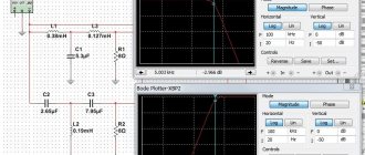
At the request of readers, I measured how much the filter suppresses interference. This didn’t work out very well - it’s difficult for me to generate high-voltage pulses at home, and I didn’t do it. But the generator produced HF interference (small amplitude, but what's the difference?). Here are two tests. They may not be very accurate - the amount of suppression may be somewhat underestimated. A soldering iron was included as a load in the filter.
The first test is 30 kHz frequency suppression. This frequency is often used in switching power supplies (computer ones, for example), and the network is “clogged” with this frequency. Here are the voltage waveforms at the input and output:
- Blue is input, red is output. The scales are the same. Suppression times 8, which is very good for a simple filter, especially one made from scrap materials.
- The second test is really high frequency interference at 200 kHz:
Here the output voltage is 100 times larger than the input voltage. Interference suppression approximately 350 times!!! So RF interference will not get through.
There are some good reels on sale:
They are wound with a fairly thick wire on a ferrite core, shaped like a dumbbell. There is a heat shrink tube on the outside. These coils have a fairly large inductance with a decent current (and several standard sizes - the larger the size, the greater the product of inductance and maximum current). Having such coils, making filters is a pleasure. The circuit is almost the same, now the coils are “powerful” and resistors in the interference suppression circuit are not needed:
In principle, everything remains the same, but except for the coils, the capacitor has changed. This is a specialized capacitor designed to work in filters (these are found in computers and uninterruptible power supplies. And the voltage of 280 V for which the capacitor is designed is the effective value of alternating current (this is indicated by the “280V ~” sign on the case). The same as 220. That is, you don’t need to divide the voltage written on the capacitor by the root of 2 to find out what maximum AC voltage it can be turned on at. Just 280 volts. And we have 220, a decent margin. That’s what happened :
Blue - varistor, which was in this “filter” extension cord; next to it there are black coils; according to good practice, they should be placed so that their axes are perpendicular, but first I took a photo, then bent the coil (the bottom one in the photo), then twisted everything, and only then I remembered that I took the photograph incorrectly! I was too lazy to take it apart again, sorry! Yellow is a capacitor. As far as I have met them, they are all yellow.
The resistor that discharges the capacitor is not installed here - a device will be connected to this filter all the time, which will discharge the capacitor. And if I take off this filter once in my life, I won’t forget to discharge it. I would just be too lazy to look for and solder a resistor, but I categorically recommend that everyone not take my example in this and install the resistor!
That's all! Very simple and very good!
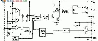
Scheme of SF protection against network interference
A typical network filter circuit is the basis of all devices of this type, with the exception of additional details. The classic is connecting to the points: Ground, Phase and Zero. A varistor VDR 1 is installed at the input. It suppresses voltage surges in the mains current. With a high voltage surge, the resistance of the varistor drops sharply, thereby preventing the interference from passing further through the circuit.
To dampen small voltage changes, inductor Tr1 and three capacitors C are used. Capacitors C1, C2 and C3 are reactive radio components that constantly change the resistance level. It increases sharply when the current frequency changes.
Normal current passes through the filter unimpeded. At the same time, high-frequency interference is delayed in the SF. The filter resistance is directly proportional to the current frequency. Both indicators increase simultaneously, which makes it possible to delay interference on the way to the consumer.
Note! A three-wire power supply network may be subject to interference in the phase-zero, ground-phase, and ground-zero sections. Effective suppression of such negative phenomena is carried out by normal standard grounding of the SF.
Examples
Fig. 17 Ampleon
Fig.18 MiniCircuits
Fig.19 CREE
Fig.20 SkyWorks
Fig. 21 Qorvo (crystal)
The last example requires a little explanation: for crystals, plane-parallel capacitors are usually used. They look like this:
Fig.22 View of the capacitor (Tecdia)
Thank you for your attention!
I invite you to my Instagram and read my past articles.
Ways to Improve the Filter Circuit
There are many options for improving the network filter circuit. One of them is ingenious and allows you to significantly save energy consumption. The essence of the method is as follows:
- Open the housing of the multi-connector SF extension cord.
- One of the current-carrying busbars is cut.
- The segments are connected to a 5 volt relay, designed for switching current 3A, 250 V.
- The other two relay contacts are connected by wires to a USB connector at the end.
- The connector is connected to the USB input of the TV.
The result is a controlled power system consisting of a TV, a digital set-top box and a satellite dish power supply. If previously, when the TV was turned off, all parts of the system remained in standby mode, then with the upgraded filter they are completely turned off. As soon as you turn on the TV using the remote control, all the switched devices are also activated and vice versa.
Additional Information. Various modernized SFs can always be found on the radio market, but they are quite expensive. Therefore, it is much more profitable to improve the device yourself.
In another case, they take the path of adding an LC filter to the SF, which, in addition to suppressing interference from the network, reduces mutually occurring electrical interference from connected consumers.
A standard varistor (470 V) often does not trip the automatic fuse. It is replaced with a similar device designed for a voltage of 620 V. This allows you to suppress interference from a running washing machine, vacuum cleaner and other powerful electrical equipment.
Home craftsmen equip surge protectors with audible alarms. When the voltage level in the network exceeds 280 V, the filter notifies you with a signal.
How to choose?
The best option, which combines the properties of a surge protector and a stabilizer in one device, is a UPS with a battery, which is an uninterruptible power supply. The UPS is characterized by a smooth sinusoidal voltage drop, so it is used to stabilize the operation of household appliances and computers. The choice of a surge protector for home or professional use is made after studying all the features and characteristics of the electrical network. Many modern buildings have grounding, but there are old buildings that do not have such protection; for such cases, a reliable surge protector is required. Often in one apartment different filters are used for the TV, for the refrigerator, for home equipment.
When choosing a surge protector, you need the following.
- Determine the power of the device - calculate how many devices and with what power will be simultaneously connected to the filter, add a margin of at least 20% to the total number.
- The parameter of the maximum energy of the input pulse is important - the higher this indicator, the more reliable the network device will be.
- Determine whether there is a thermal fuse in the filter that protects the filter from overheating.
- Determine the number of sockets to connect, and if devices need to be frequently disconnected from the network, then it is better to choose a filter with autonomous shutdown of each socket.
- Consider what length of electrical cable will be needed.
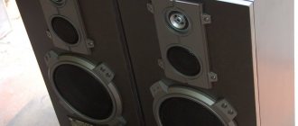
Line filter with 2 winding choke
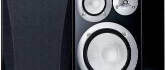
SF based on a choke with two windings is used for sensitive audio equipment. Speakers are sensitive to power supply interference. If any occur, the speakers distort the sound and emit extraneous background noise. Radio equipment connected to the network via a SF with a 2-winding coil is protected from such interference.
The circuit is assembled on a separate printed circuit board. You will need several capacitors and a homemade inductor. It is made as follows:
- A ring made of ferrite grade NM with a magnetic permeability from 400 to 3000 can be taken from old electrical equipment.
- The magnetic core is wrapped in cloth and coated with varnish.
- PEV brand wire is used for winding. Its cross-sectional area depends on the magnitude of the load. Powerful consumers require a significant increase in this parameter.
- Winding is carried out with two wires in different directions.
- Make 10, 12 turns of each conductor.
- Capacitors are installed at the beginning and end of the circuit. They must withstand voltages up to 400 V.
SF with 2 winding choke
The windings of the inductor are connected in series order. Therefore, the magnetic fields of the coil are mutually absorbed. When a high frequency current passes, the resistance of the inductor increases sharply. Capacitors absorb and short-circuit interference.
The printed circuit board is placed in a separate metal case. As a last resort, the circuit is fenced off with metal sides. This is done in order to eliminate additional interference from stray electromagnetic fields.
With each new generation of electronic equipment, increased demands are placed on the quality characteristics of the mains current. In order not to have to repair sensitive electronics, you must connect them through surge protectors. If you need to filter the current for a small number of consumers, then you can take the economical path and make a surge protector with your own hands.
Testing
As attentive readers may have noticed, I test everything. When developing test boards (the circuits from which will later be copied into the final product), I usually make these additional boards with elements of power supply circuits.
Fig. 15 EVB for an amplifier crystal, a board for checking the frequency response of separating capacitors, for checking the frequency response of the power filtering circuit
Here's a Bias Tee board from MiniCiruits.
Fig. 16 Board for TCBT-123 (photo from my Instagram)
Typically, amplifier IC manufacturers provide recommendations on the components in the power supply. However, sometimes this is a standard set that may not be very suitable for a particular application. Also, standard recommendations are not suitable if it is necessary to supply pulsed power.