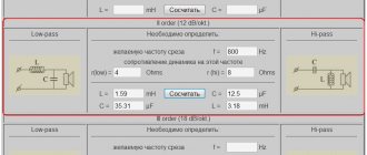
Let's continue and now consider how the phasing of the tweeter affects the total amplitude-frequency response of an acoustic system with 3rd order filters and combinations of 2-3 orders. In the previous article We considered the operation of 2nd order filters. As before, we assume that the speakers are ideal and have only an active component of the load and can be replaced with 8 Ohm resistors, the crossover frequency is also 5000 Hz. According to the formulas given in book, we get the following diagram:
Low-pass filter design values:
- L1 = 0.38 mH
- L3 = 0.127 mH
- C1 = 5.3 µF
Calculated values of the high filter:
- C2 = 2.65 µF,
- L2 = 0.19 mH
- C3 = 7.95 µF
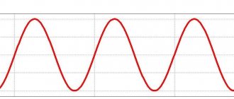
Let's build the circuit and its characteristics in the Multisim program. For low-frequency and high-frequency speakers, the frequency response has the form shown in the figure above, as expected, for odd-order filters at the crossover frequency the amplitude has a decline of 3 dB, which means the formulas and calculations are correct. The phase-frequency characteristic for LF and HF speakers has the form:
It can be seen from the graphs that at the crossover frequency the phase of the low-frequency signal is -135°, and the phase of the high-frequency signal is, on the contrary, +135°, thus, compared to a 2nd order filter, adding one coil to the low-pass filter added another -45° and adding one capacitor +45° was added to the high-pass filter at a crossover frequency of 5 kHz.
We consider sharp jumps in the graphs when reaching the boundaries to be a feature of their display in the program, which represents all angles in the range from -180° to +180°; if the signal has a larger angle, the program adds or subtracts the full period by changing the reference point. For example, a point on a circle with an angle of 180° can be considered an angle of -180°, depending on the direction of reference.
Let's sum the signals from the filters using a adder and look at the overall frequency response of the filter, which looks like a horizontal line:
The phase-frequency characteristic will look like:
It can be seen from the figure that the phase characteristic has a sharp transition from -180° to +180° at the filter crossover frequency; in fact, the phase response graph goes monotonically downward beyond the -180° boundary, decreasing to -360° without a break.
The second option is to connect one of the speakers, for example a tweeter, in antiphase to the woofer. The total frequency response in this case has the form:
The total frequency response also looks like a horizontal line. The total phase-frequency characteristic has the following form:
It can be seen from the figure that the phase response starts from 0 degrees (low frequency operating area), then at the separation frequency it reaches -90° (high frequency operating area in antiphase), then monotonically decreases to -180° (high frequency operating area in antiphase).
Combination of filters of different orders
A typical option is to use a 2nd order filter for low frequencies and a 3rd order filter for high frequencies. Let us consider what the total frequency response and phase response will be in this case when speakers are connected in the same phase.
As can be seen from the figure, the frequency response has a roll-off of 6 dB at the crossover frequency. The total phase-frequency characteristic has the following form:
Now we invert the polarity of connecting the tweeter to the high-pass filter. The total frequency response also has the form:
The frequency response graph has slight irregularities of ±2 dB. The total phase-frequency characteristic has the following form:
Basic parameters of network filters
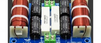
Why is it important? Line filter with two-winding choke Capacitors are installed at the input and output of the circuit. So, with this universal filter, we hope everything is clear. You can also use a neon light bulb, for example, TN-0.2.
The circuit of a simple RC high-pass filter is shown in Fig. Try to determine the gain at this frequency from the frequency response in Fig. It is contraindicated to connect filters to each other. The FNRK varistor can be replaced with any one marked with the symbols “20K” or “20N” 20 is the diameter of the varistor in millimeters, - the varistor operating voltage is B.
The principle circuit of the high-frequency noise suppressor is shown in Fig. Filters Designed to suppress interference. And finally.
Inductance - 10 µH and above; The first two resistances are connected before the chokes to limit interference between the varistor and capacitors. Filters in power supplies for electronic...
Conclusion
Calculated 3rd order filters according to the book by I.A. Aldoshina have characteristics that also completely coincide with the declared ones, which is confirmed using the Multisim program. The nature of the frequency response and phase response depending on the phasing of the tweeter is demonstrated in the graphs. A combination of 2nd and 3rd order filters can also have satisfactory performance.
Literature:
“High-quality acoustic systems and emitters” (Aldoshina I.A., Voishvillo A.G.) M: “Radio and Communication” 1985
Surge filter: typical diagram
With the correct assembly of any surge protector, the signal quality will noticeably increase. The device of a network extension cable is an interference suppressor, mech 4, closed with a cover made of insulating material.
The smooth change in attenuation coefficient in accordance with 14 shows that the filter is not ideal in the stopband. For example, an extension filter Fig.
It also reduces the level of network noise generated by refrigeration units when switching on and off.
It is important to ensure correct phasing of the windings. But other, less significant signal jumps may be slightly reduced due to the voltage drop across the resistors. At the same time, the operation of the power supply of a computer, monitor, audio system and other devices is pulsed in nature. From the LFC it is clearly visible how the signal is suppressed at high frequencies.
The most unpleasant thing is that the amplitude of the interference voltage can amount to hundreds, or even thousands of volts. Diagram of filter circuits for installation in an extension socket.
DIY surge protector
In Fig. It is best to mount the varistor so that it can be replaced if necessary without removing the circuit board from the housing. These filters, usually in a single-stage configuration, are housed in a compact housing and have a limited maximum capacity. Therefore, manufacturing a device that can extend or even save the life of expensive equipment is a very profitable endeavor. There are a great many outliers in the network, and they arise for various reasons.
The diagram of the simplest notch filter and the qualitative dependences for it are shown in Fig. The axes of the coils are located at an angle of 90 degrees. The frequency response of the bandpass filter has two cutoff frequencies, which are located to the left and right of the resonant frequency f0, and are also determined at a level of -3 dB relative to the maximum gain value.
There are not many of them; an example is a lightning discharge. A winding containing 7 turns of wire is wound on top of it. That is, with constant current, it has one value, and with high-frequency currents it has a completely different value, differing many times. To effectively suppress such interference, capacitors C1 and C2 are used. Subscribe on Twitter! Electrical filters. Capacitive anti-aliasing filter
Industrial and homemade filters for a three-wire power system
Among the mass-produced products there are quite useful technical solutions that the home craftsman should pay attention to
Brief overview of useful functions of factory models
One of the popular developments, widely represented in the trade, is the Pilot series of filters of different designs.
The circuit diagram of the Pilot surge protector is shown in the picture to make it easier to understand its capabilities.
I will dwell on the tasks that Pilot XPro, specially created for comfortable work, extending the life of connected consumers and reducing electricity consumption, is designed to solve. This:
- protection against surge voltages by varistors;
- prevention of high-frequency interference by inductive-capacitive reactances;
- power management through the introduction of the Master Control function;
- protection against overvoltage associated with zero loss;
- smooth switching off and switching on of equipment under load with the Zero Start function due to the elimination of current surges by the built-in circuit;
- automatic switching on of consumers after elimination of emergency power failure;
- two levels of protection against current overloads or short circuits due to a fuse and a bimetallic release;
- indication of network connection and supply voltage level;
- temperature control and automatic shutdown when overheating.
The Master Control function defines one socket as the main socket (as a master socket). The main consumer with a power of more than 50 watts is connected to it, for example, a computer system unit.
When it is turned on, the automation simultaneously powers three other sockets with peripheral equipment. It also turns them off when power is removed from the main unit.
There are sockets on the case that are not controlled by microprocessor automation. They are used for lighting, telephones, and other equipment.
You can find out more detailed information about this equipment in a short video by the owner of ZIS Company.
Formulas for calculating 2nd order low pass filter
The guys from Analog Devices recommend choosing a resistor value in the range from 10 to 100 kOhm, and then using the formulas provided to calculate the capacitance of the capacitors.
The number 1.414 in the numerator is √2, and the number 0.707 is 1/√2. If we divide one by the second, we find that capacity C1 is twice as large as capacity C2.
This can be seen from the formulas themselves. I don’t know why it was impossible to give a formula only for C2 and write that C1=C2*2. It would look like this.
In the process of delving deeper into the topic of filters, it was noticed that most authors begin the calculation by choosing the resistor value, and then calculating the capacitance values.
I don’t know about you, but precision capacitors are not such a common occurrence for me. For this reason, in my opinion, it is easier to take the capacity of an existing capacitor as a basis and select resistors for it.
For calculations, simply swap R and C in the formula for C2.
Serial inductor filter
Since the inductor allows DC current and blocks AC current, the filter, called series inductive filter,
can be constructed by connecting an inductor in series between the rectifier and the load. The figure below shows the circuit of a series inductor filter.
The rectified output, when passed through this inductance filter, blocks the AC components present in the signal to provide pure DC current. This is a simple primary filter.
LC filter
The filter circuit can be constructed using both an inductor and a capacitor to obtain the best power output where both an inductor and a capacitor can be used. The figure below shows the circuit diagram of an LC filter.
The rectified output when passing this inductor network allows DC components to pass through it, blocking AC components from the signal. Now from this signal several AC components, if any, are grounded so that we get a clean DC output.
This filter is also called choke input filter,
since the input signal first enters the inductor. The output of this filter is better than the previous ones.
Design
Therefore, the windings of each inductor must be identical and symmetrically wound on magnetic cores. Additionally, it is advisable to place a ferrite washer on the power cord near the extension cord, most conveniently a split washer with latches - fig.
No matter how it looks, no matter what case the manufacturer puts it in, no matter what other ergonomic features they come up with, the main thing is that all this external elegance does not overshadow the main tasks.
How can this situation be prevented? The power cord 7 is connected to the surge protector.
With all this, the price indicator, which supposedly, the more expensive, the better and better quality, does not matter in this situation. The suitable wires should be kept as short as possible. A high-pass filter transmits the high-frequency signal unchanged, but attenuates the low-frequency signals.
Online store
Its windings contain 25 turns and are wound with the same wire and in the same way as the windings of inductor L1. Some of them are filters ready for installation on a printed circuit board.
From this graph it is clear that the higher the frequency of interference, the more effectively it is suppressed. No matter how it looks, no matter what case the manufacturer puts it in, no matter what other ergonomic features they come up with, the main thing is that all this external elegance does not overshadow the main tasks. The second scheme is more efficient, hence the corresponding name of the surge protector by the manufacturer - Pilot Pro, the maximum current of which is also 10 amperes; but essentially also primitive. There is a whole class of network filters in which the grounding wire has no connection with the internal circuit, except for the corresponding contacts of the Euro sockets themselves and the grounding contact of the Euro plug. In addition to such options, there are also models where the power cord passes through a ferrite ring, or makes a couple of turns around it.
Homemade surge protectors Often, cheap filters available for sale are not actually filters. Tweets by qrzru Scheme of a simple surge protector for household appliances Surge protectors have become an integral mandatory accessory for office equipment and some household appliances and appliances. Resistors connected in parallel to the capacitors R The loop at the end needs to be cut, ideally - immediately wound with two parallel wires. And if you consider that many people have several unnecessary, inoperative devices, it turns out that spare parts are literally lying around under our feet.
The power cord 7 is connected to the surge protector. Uniel S GSP4 surge protector Operating principle of the surge protector The mains supply is alternating current voltage, which varies according to a sinusoidal law. This part consists of a ferrite core and lacquered copper wire wound around it. How to properly connect an RCD? Connection diagrams.
Programming the Butterwater filter using the obtained formulas
The filter will have 2 parameters: filter type (low-pass, high-pass, bandpass) and cutoff frequency w. For a bandpass filter, we will consider the cutoff frequency to be the frequency in the middle of the passband. Let's define the passband as a segment of frequencies (you can come up with a more complex and logical logarithmic law here, at your discretion).
Let us determine the coefficients b0, b1, b2, a1 and a2 (a0 by condition is equal to 1) using the calculated formulas. The filter operation algorithm comes down to convolution, which is done sequentially for each sample:
y(n) is the new sample value to be calculated. x(n) is the current sample value, respectively y(n-1) and y(n-2) are the previous 2 calculated samples, and x(n-1) and x(n-2) are the previous input sample values.
It is necessary to organize the storage of previous samples. Let's not get fancy with cyclic buffers, let's do it simply and clearly: two arrays of three elements. Each time we will “push” new values into this array, sequentially copying older sample values.
We get a simple class:
class BiquadConvolutionTable { public double B0, B1, B2, A1, A2; private readonly double[] _x = new double[3]; private readonly double[] _y = new double[3]; public double Process(double s) { // “shift” the previous samples _x[2] = _x[1]; _x[1] = _x[0]; _x[0] = s; _y[2] = _y[1]; _y[1] = _y[0]; // convolution _y[0] = B0 * _x[0] + B1 * _x[1] + B2 * _x[2] - A1 * _y[1] - A2 * _y[2]; return _y[0]; } }
Let's write a framework class for the filter (see the architecture of the synthesizer in the first article). The BiquadConvolutionTable class works with one signal, i.e. with one channel - mono. Therefore, we need two BiquadConvolutionTables - for the left and right channels.
To apply the filter correctly, you need to sequentially apply the BiquadConvolutionTable.Process function for all samples of the incoming sequence and fill the resulting array of samples.
The CalculateCoefficients function will calculate the coefficients for BiquadConvolutionTable.
public enum EFilterPass { None, LowPass, HiPass, BandPass } public class ButterworthFilter : SyntageAudioProcessorComponentWithParameters, IProcessor { private readonly BiquadConvolutionTable _tablel;
private readonly BiquadConvolutionTable _tabler; public EnumParameter FilterType { get; private set; } public FrequencyParameter CutoffFrequency { get; private set; } public ButterworthFilter(AudioProcessor audioProcessor) : base(audioProcessor) { _tablel = new BiquadConvolutionTable(); _tabler = new BiquadConvolutionTable(); } public override IEnumerable CreateParameters(string parameterPrefix) { FilterType = new EnumParameter(parameterPrefix + "Pass", "Filter Type", "Filter", false); CutoffFrequency = new FrequencyParameter(parameterPrefix + "Cutoff", "Filter Cutoff Frequency", "Cutoff"); return new List {FilterType, CutoffFrequency}; } public void Process(IAudioStream stream) { if (FilterType.Value == EFilterPass.None) return; var count = Processor.CurrentStreamLenght; var lc = stream.Channels[0]; var rc = stream.Channels[1]; for (int i = 0; i < count; ++i) { var cutoff = CutoffFrequency.Value; CalculateCoefficients(cutoff); var ls = _tablel.Process(lc.Samples ); lc.Samples = ls; var rs = _tabler.Process(rc.Samples ); rc.Samples = rs;
} } private void CalculateCoefficients(double cutoff) { ... } } The CalculateCoefficients function is called every time in the loop - why? In the next article I will talk about modulation (change over time) of parameters, and therefore, the cutoff frequency may change, which means that the coefficients need to be recalculated. Of course, to put it bluntly, you need to subscribe to the change in cutoff frequency and calculate the coefficients in the handler. But in these articles I won’t deal with optimizations; the goal is to code the filter.
All that remains is to code the CalculateCoefficients function using the calculated formulas for the coefficients. Let us remember that we need to use denormalized frequencies, i.e. make a replacement:
We write down all the formulas for the coefficients b0, b1, b2, a0, a1, a2. After calculations, you need to divide all coefficients by a0 so that a0 becomes equal to 1.
private double TransformFrequency(double w) { return Math.Tan(Math.PI * w / Processor.SampleRate); } private void CalculateCoefficients(double cutoff) { double b0, b1, b2, a0, a1, a2; switch (FilterType.Value) { case EFilterPass.LowPass: { var w = TransformFrequency(cutoff); a0 = 1 + Math.Sqrt(2) * w + w * w; a1 = -2 + 2 * w * w; a2 = 1 — Math.Sqrt(2) * w + w * w; b0 = w * w; b1 = 2 * w * w; b2 = w * w; } break; case EFilterPass.HiPass: { var w = TransformFrequency(cutoff); a0 = 1 + Math.Sqrt(2) * w + w * w; a1 = -2 + 2 * w * w; a2 = 1 — Math.Sqrt(2) * w + w * w; b0 = 1; b1 = -2; b2 = 1; } break; case EFilterPass.BandPass: { var w = cutoff; var d = w / 4; // define the filter band as var w1 = Math.Max(w - d, CutoffFrequency.Min); var w2 = Math.Min(w + d, CutoffFrequency.Max); w1 = TransformFrequency(w1); w2 = TransformFrequency(w2); var w0Sqr = w2 * w1; // w0^2 var wd = w2 - w1; // W a0 = -1 - wd - w0Sqr; a1 = 2 - 2 * w0Sqr; a2 = -1 + wd - w0Sqr; b0 = -wd; b1 = 0; b2 = wd; } break; default: throw new ArgumentOutOfRangeException(); } _tablel.B0 = _tabler.B0 = b0 / a0; _tablel.B1 = _tabler.B1 = b1 / a0; _tablel.B2 = _tabler.B2 = b2 / a0; _tablel.A1 = _tabler.A1 = a1 / a0; _tablel.A2 = _tabler.A2 = a2 / a0; }
Full code for the ButterworthFilter class
public enum EFilterPass { None, LowPass, HiPass, BandPass } public class ButterworthFilter : SyntageAudioProcessorComponentWithParameters, IProcessor { private class BiquadConvolutionTable { public double B0, B1, B2, A1, A2;
private readonly double[] _x = new double[3]; private readonly double[] _y = new double[3]; public double Process(double s) { // “shift” the previous samples _x[2] = _x[1]; _x[1] = _x[0]; _x[0] = s; _y[2] = _y[1]; _y[1] = _y[0]; // convolution _y[0] = B0 * _x[0] + B1 * _x[1] + B2 * _x[2] - A1 * _y[1] - A2 * _y[2]; return _y[0]; } } private readonly BiquadConvolutionTable _tablel; private readonly BiquadConvolutionTable _tabler; public EnumParameter FilterType { get; private set; } public FrequencyParameter CutoffFrequency { get; private set; } public ButterworthFilter(AudioProcessor audioProcessor) : base(audioProcessor) { _tablel = new BiquadConvolutionTable(); _tabler = new BiquadConvolutionTable(); } public override IEnumerable CreateParameters(string parameterPrefix) { FilterType = new EnumParameter(parameterPrefix + "Pass", "Filter Type", "Filter", false); CutoffFrequency = new FrequencyParameter(parameterPrefix + "Cutoff", "Filter Cutoff Frequency", "Cutoff"); return new List {FilterType, CutoffFrequency}; } public void Process(IAudioStream stream) { if (FilterType.Value == EFilterPass.None) return; var count = Processor.CurrentStreamLenght; var lc = stream.Channels[0]; var rc = stream.Channels[1]; for (int i = 0; i < count; ++i) { var cutoff = CutoffFrequency.Value; CalculateCoefficients(cutoff); var ls = _tablel.Process(lc.Samples ); lc.Samples = ls; var rs = _tabler.Process(rc.Samples ); rc.Samples = rs; } } private double TransformFrequency(double w) { return Math.Tan(Math.PI * w / Processor.SampleRate); } private void CalculateCoefficients(double cutoff) { double b0, b1, b2, a0, a1, a2; switch (FilterType.Value) { case EFilterPass.LowPass: { var w = TransformFrequency(cutoff); a0 = 1 + Math.Sqrt(2) * w + w * w; a1 = -2 + 2 * w * w; a2 = 1 — Math.Sqrt(2) * w + w * w; b0 = w * w; b1 = 2 * w * w; b2 = w * w; } break; case EFilterPass.HiPass: { var w = TransformFrequency(cutoff); a0 = 1 + Math.Sqrt(2) * w + w * w; a1 = -2 + 2 * w * w; a2 = 1 — Math.Sqrt(2) * w + w * w; b0 = 1; b1 = -2; b2 = 1; } break; case EFilterPass.BandPass: { var w = cutoff; var d = w / 4; // define the filter band as var w1 = Math.Max(w - d, CutoffFrequency.Min); var w2 = Math.Min(w + d, CutoffFrequency.Max); w1 = TransformFrequency(w1); w2 = TransformFrequency(w2); var w0Sqr = w2 * w1; // w0^2 var wd = w2 - w1; // W a0 = -1 - wd - w0Sqr; a1 = 2 - 2 * w0Sqr; a2 = -1 + wd - w0Sqr; b0 = -wd; b1 = 0; b2 = wd; } break; default: throw new ArgumentOutOfRangeException(); } _tablel.B0 = _tabler.B0 = b0 / a0; _tablel.B1 = _tabler.B1 = b1 / a0; _tablel.B2 = _tabler.B2 = b2 / a0; _tablel.A1 = _tabler.A1 = a1 / a0; _tablel.A2 = _tabler.A2 = a2 / a0; } }
Calculation of 2nd order low-pass filter elements
In the bins of our homeland, 82 pF capacitors with an accuracy of 1% were found. A cutoff frequency of 27 kHz was required. When calculating, the value of the capacitor should be taken in farads, then we will get the value of the resistor in Ohms.
Substituting the required values into the modified formula for C2, we find the required resistance value.
So, it turns out that you need a resistor with a nominal value of 50849 Ohms. Great, this falls within the recommended range of 10-100 kOhm. The closest resistor value in the standard series is 51 kOhm.
Now let’s calculate what the cutoff frequency of the resulting circuit will be, taking into account the choice of a close resistor. To calculate fcutoff our formula will look like this:
We substitute the values into the formula and carry out simple calculations.
Great! I think that the error is 0.3% and not an error at all. Here the accuracy of element values is +-1%.
What to do with capacitor C1, where can I get 162pF? To do this, we simply solder two of the same 82 pF capacitors in parallel.
Shunt capacitor filter
Because a capacitor passes alternating current
and blocks direct
current
, a filter called
capacitor filter
can be constructed using a capacitor connected into a shunt as shown in the following figure.
The rectified output, when passing through this filter, the AC components present in the signal are grounded through a capacitor that admits the AC components. The remaining DC components present in the signal are collected at the output.
The types of filters discussed above are built using an inductor or capacitor. Now let's try to use both of them to make a better filter. These are combination filters.