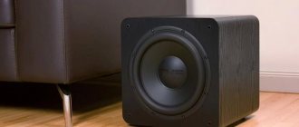
Advantages and disadvantages of using an interstage transformer
The main advantage of an interstage transformer is its ease of assembly. It is not difficult for a novice amateur to create a device at home. The device functions efficiently, the circuits are easy to understand, and you do not need to delve into huge complex formulas to create a working and reliable device.
A significant disadvantage of the interstage transformer is the bulkiness of its structural components. As a result of installing the device in an amplifier or rectifier, the device acquires a lot of weight and increases in size. Modern types of transformers are smaller in size, but are approximately identical in functionality. Consequently, interstage ones can be used, but only if the radio amateur does not have the opportunity to buy new, smaller equipment or lacks financial resources.
Another disadvantage of the device is the occurrence of a phase shift during operation. As a result, it cannot operate at high frequencies, which makes the scope of application limited.
↑ Listening
The perception of mono sound is very different from stereo, you need to get used to it.
I expected more from the circuit, I thought, I’ll turn it on and here it is, nirvana. But it didn't happen. I changed records, changed the phono stage, and connected mine in mono mode to compare the sound. First impressions are contradictory. The new circuit has a high resolution, as my friend said, “lays out the instruments on the shelves,” but the sound did not seem “comfortable.” I digitized several tracks using my phono stage in mono mode and a prototype of a new circuit, recorded the tracks on a CD and asked two of my fellow music lovers to listen and give their opinion. The tracks on the disc were arranged in random order; those listening did not know through which phono stage the recording was made.
As a result of blind listening, the first listener was unable to give preference to any of the devices. The second divided by genre, giving preference in rock music to the first (let’s call it old) corrector, noting that it “blurs” the sound, and in classical and instrumental music - to the second (new) phono preamplifier.
I, knowing where what was playing, also could not finally decide, although the second phono preamplifier was more “accurate”, but the “hard” and somewhat “tiring” sound did not give me rest.
I would like to note that all my home-grown definitions of sound, such as “precise”, “blurred”, “uncomfortable”, “hard”, “tiring”, etc., are very arbitrary and hardly perceptible when listening. Perhaps they are a consequence of self-hypnosis and do not deserve the attention of a serious reader.
Circuits of interstage transformers
Circuits of interstage transformers are selected depending on the type of equipment and equipment used. A resistive load parallel to the grid will be needed in most cases. The fact is that it is necessary to bypass the secondary base, since without this the first stage is heavily loaded and the indicators of the input capacitance of the next stage are enhanced. If the transformation ratio is one to one, then the shunting is carried out in an identical way (up to 10 kOhm).
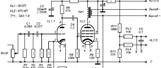
For tube amplifier
Circuits designed for an amplifier using transformers cannot be found in the technical literature. This is explained by the fact that the devices are selected independently; the standard winding pattern changes depending on the initial characteristics.
According to the circuit calculated for OSM 0.1 lamp Ri < 2 kohm, it is necessary to take iron 25 by 40. The area is 9 squares, the primary winding is 133 turns per layer, the device has 3, 6, 6 and 4 layers of four sections. The total number of turns in the primary winding is 2394. In the secondary there are 6, 6 and 6 layers, 133 pieces each. Total quantity is 2394. Clearance is required if current exceeds 12 mA. If it does not reach, then you can do without a gap.
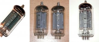
For 6 6g
For 6 6g it is assembled in an identical way, but the number of windings increases. In the standard scheme, the dimensions are 17 by 66 millimeters. The core used is small - about 5 square centimeters. It should be taken into account that the winding resistance during calculations should not exceed 10 percent of the internal resistance of the equipment.
For push-pull amplifier
The principle of assembling four pieces of secondary windings is used. They are arranged in parallel in pairs, and different resistance indicators are coordinated. The required transformation ratio is 20 to 1. Impregnation with ceresin is desirable.
For hybrid amplifier
An interstage TS is also suitable for a hybrid amplifier. A set of necessary materials 32 by 50 is taken, winding is made 14 by 46 millimeters. The primary layer is made 0.28 and is not covered. A total of 14 turns of five sections are obtained. It is estimated that 20 layers yield over 2800 turns, measure with instruments.
The secondary winding is produced in an identical manner. First, 0.28 millimeters without the use of varnish, the total number of turns is 2800. The insulation is taken between the windings by 0.2 millimeters, it is permissible to use paper. Shunting through the secondary is not necessary; it will not affect the power indicators.
Contents
- 1 Background
- 2 Phono stage circuit by John Broskie
- 3 Listening
- 4 New background corrector
- 5 Lamp selection
- 6 Transistor selection
- 7 Organization of bias of the first stage
- 8 Output transformers
- 9 Power supply
- 10 Delay of filament voltage and anode voltage
- 11 Corrector body
- 12 Parameters of my phono stage assembly
- 13 Results
- 14 Literature and sources mentioned
- 15 tracks digitized by my proofreader for listening
- 16 Projects of modules for EAGLE CAD
- 17 After what was written
What you need to create a device with your own hands
You will need wire cores; select a certain number of turns before starting work. In terms of time, making a standard model takes a beginner at least 4-5 fans. Be prepared for the fact that you will have to try, put in a lot of accuracy and patience.
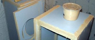
Initially, a device for rotation is made. It can be made from a car control panel speedometer. Mounts vertically on a stand - use a regular stand with a hole in the top. The speedometer is screwed into the hole, the meter bearing axles are connected with wire. The results are viewed through a homemade window. The coil is secured with gaskets.
↑ Organization of bias of the first stage
I looked at LED bias and automatic bias with a large capacitor bridging the resistor. Automatic offset allows the use of lamps with a greater spread of halves, although it does not exclude the selection of lamps. Unfortunately, the measurement results of the module with automatic bias and LED bias were not saved. There are only two screenshots left, with automatic bias in the first stage and an output level of 250 mV 1 kHz (-12 dB) and with LED bias in the first stage and an output level of 315 mV 1 kHz (-10 dB). In both cases, the level of the second harmonic is 70 dB lower than the first (~0.03%), the remaining harmonics are lost in noise.
Automatic bias, 250 mV input signal.
Rice. 32.
LED bias, 315 mV input signal
Repeated THD measurements were carried out on the assembled device with an output transformer stage and noise levels were measured. When performing THD measurements of an auto-biased and LED-biased phono stage, the parameters are very close (same channel with R3 and C2 replaced by an LED).
Rice. 33.
Auto offset
Rice.
34. Same module, LED bias
There is a difference in the level of intrinsic noise and interference when using different types of bias in the first stage of a given phono stage. When measuring parameters with different types of bias, it turned out that with LED bias the noise level is 3 dB lower and has a slightly different spectrum. I think that this depends on the different sensitivity of the LED and the resistor to electromagnetic interference from the transformer.
When biased by the LED, the stage noise has its greatest amplitude in the range from 20 to 40 Hz, then begins to gradually decrease. With a real amp and speakers (at maximum volume), it's like a steady blowing sound, soft and not annoying.
With automatic shifting, the noise spectrum is dominated by the frequency of 50 Hertz and its harmonics, 100, 150, 200 Hertz, etc. The nature of noise and interference with automatic shifting is perceived as louder and more unpleasant.
Rice. 35.
Left channel with auto shift, right channel with LED shift
Rice.
36. Both channels with LED bias
This is not critical, since no one will listen at full volume. On the other hand, selecting lamps for the first stage with automatic bias will be less problematic. If you place the phono preamplifier and power supply in different housings and separate them at some distance, then using automatic bias seems more preferable.
When listening to musical material, differences are at the level of “impression” and “appearance”. I think that during blind listening it will be extremely difficult or simply impossible to distinguish.
As a result, the module board is wired for automatic bias, but in the final version I used bias with an LED installed in the seat of the electrolytic capacitor C2. I continued to listen to the layout for some time, changing the musical material and making sure (convincing myself?) that this was the final version.
If the input sensitivity of your ULF is up to 500 mV, then an additional stage may not be needed; you will only need to reconsider the value of the output coupling capacitor C11. In my case, the capacitance of 0.47 uF is designed for the input resistance of the third stage of 166 kOm.
Module parameters:
gain at a frequency of 1 kHz ~68 (depending on the gain of the tubes used, in my case the spread was from 60 to 68). With an input signal of 2.5 mV, the output will be ~170 mV. THD 0.012%, unweighted noise 72 dB, measured under such “field” conditions.
Rice. 37.
Measuring the parameters of the phono stage module.
The power transformer is simplified; a second high-voltage anode supply stabilizer is not needed. But the nominal sensitivity of my ULF is 1 V and 170 mV at the input is not enough, you need to make a third stage. I haven't come up with anything better than a transformer stage with a gain of 3. The gain headroom is good, because when I got an MC head with a high output of 1.6 mV, I was able to listen to music without changing anything.
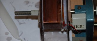
Transformer creation and winding technology
The wires are located at a distance of up to 1 meter from the device.
The rod is attached at an angle of 55-60 degrees on the opposite side. For ease of rotation, place the technical wheel on the shaft.
The tails are inserted through pre-made holes. 2-3 more pieces are cut out, so that in case of careless winding the outputs remain. Winding is carried out with the installation of paper spacers between each layer (the calculation of their number will be given above).
Winding is done as tightly as possible, gloves are used so that the insulation does not get on your hands. Leave the coils 2 millimeters to the walls.
↑ Lamp selection
In their article “RIAA amplifiers - corrections on vacuum triodes for “high-speed” (electrodynamic) pickups” E. Babichenko and I. Gaponov do not recommend using the 6N23P lamp in phono stages.
“...The two-stage 6N23P crunches disgustingly...” Apparently this means the use of this lamp in resistive cascades with a common cathode. Many negative reviews about the use of this lamp can be found on the Internet. In general, reviews about the sound of the 6N23P are very contradictory.
“LIFE IN A VACUUM” Bulletin of the Association of Russian Audiophiles. “...6922/6N23P-EV is perhaps the most “debated” lamp among signal lamps. As soon as someone criticizes her, someone else will immediately come to her defense. Glass Audio has two major articles with opinions on the suitability of the 6922 in audio circuits - “Suitability of the 6DJ8 for Audio”; GA 1995/3, R. Modjesky and “Is the 6DJ8 suitable for audio?” D. Danner. GA 2/93.
If readers are interested in this technical and musical debate, we will translate and publish it. Below is data obtained by Rickard Berglund (Sweden), published in GA 1995/6. Distortion values are given for an output voltage of 1 V (RMS).... Data were obtained on several circuits, for the “honesty” of the results, including a conventional amplification circuit (with a common cathode) with and without a shunted cathode resistor, a mu - follower (with a current generator in anode), SRPP with and without cathode resistor shunt, cathode follower and load-sharing inverter..."
Rice. 16.
From the data provided by Rick Berglund, it can be seen that the 6922 lamp manufactured by Sovtek has higher gain and lower distortion relative to its more famous analogues. I can’t say whether the 6N23P-EV lamp is a complete analogue of the 6922 Sovtek lamp.
I decided to use what was available. In the first stage, you could try 6N24P, which has a different pinout, is available and they ask for it several times less, but I still wired the board for a 6N23P lamp. Let it be possible, on occasion, to test lamps from different manufacturers (6922, 6DJ8, ECC88, E88CC, etc.) without remaking the board.
In the bins there were 23 6N23P lamps and 6 6N23P-EV lamps, new and used. A preliminary selection of lamps was carried out for the identity of the halves, based on noise and compliance with passport characteristics, and candidates for the project were selected.
In addition, I would like to quote E. Karpov: “The high linearity of the cascade with a current source and the improvement in the spectrum of the output signal significantly expands the range of tubes suitable for use in high-quality low-frequency amplifiers. Such traditionally maligned tubes as 6N2P, 6N3P, 6N23P show excellent results in linearity and sound quality.”
Rice. 17.
Single channel module
Resistor R11 is made up of two two-watt resistors of 10 kOm +/- 10%. A pair of resistors 9.1 and 12 kOm looks more promising. Resistors are placed above the board on stands due to decent heat dissipation. After raising the resistors above the board level, the temperature on capacitor C5 dropped to 52, and on C6 to 49 degrees. The temperature on the C 10 capacitor does not exceed 50 degrees, despite the proximity of the lamp. The temperature at the condenser C1 is 32, at C2 - 35, at C4 - 35 and at C8 - 30 degrees. It makes sense to replace two-watt resistors (R11, R12, R13, R14) with three-watt ones to reduce heat generation. The temperature on three-watt resistors in operating mode does not exceed 60 degrees, and on two-watt resistors it reaches 90 - 95 degrees. The temperature at the lamp cylinders is about 78 degrees, all measurements were carried out on an open structure. In a closed case the temperature will naturally be higher.
↑ Delay in supply of filament voltage and anode voltage
Since the phono preamplifier uses direct coupling, it is very desirable to delay the supply of the anode voltage, and to extend the life of such expensive lamps today, also smoothly supply the filament voltage. The design uses a delay timer by V. Timofeev, described in the magazine “Amateur Radio” No. 1 for 2013, pages No. 8-11.
Rice. 51.
Standard delay timer
Rice.
52. Modification to suit my needs
May the author forgive me, but I made some changes. I changed the module’s power supply to 12 V, since my relay is not 27, but 12 V. To do this, I removed one electrolytic capacitor and installed a three-terminal stabilizer in its place. I increased the capacity of the second capacitor and placed it on its side, away from the stabilizer radiator. Film capacitors of 330 and 100 nF are soldered to the legs of the stabilizer on the reverse side of the board.
I also abandoned the two trip relays and powered the delay unit from the filament windings, rather than from a separate transformer. I always place protective resistors in parallel with the power filter capacitors. I did not turn them off while the device was operating and reduce the voltage on the relay windings after they were activated.
After assembling all the blocks into the case, it turned out that in order to reduce interference, it was necessary to remake the board with relays and powerful resistors and change the location of the filament stabilizer board.
It turned out to be convenient to observe changes in noise and interference on the circuit in the Realtime Analyzer
. You can quickly move modules, change the location of the transformer, while observing changes in the readings of the device’s own noise. As a result, the relay for switching the anode circuits with resistors had to be placed on a separate board to the power filter, the smooth filament supply relay with resistors, the delay module blocking relay, the filament midpoint resistors and the non-polar capacitor were left on the board installed above the delay block. The delay unit swapped places with the filament stabilizer. The network cable is placed in an additional screen.
↑ Parameters of my assembled phono stage
With the same gain of the channels (2% difference), the noise in the left channel is 2 dB higher than in the right.
The noise level parameters below correspond to the left channel. Gain (1kHz) 210 Input impedance 47 kΩ Total harmonic distortion (1kHz, Uout=0.75V) 0.04% Unweighted noise level - 63 dB Type C weighted - 66 dB Type A weighted - 78 dB Output impedance - 560Ω Characteristic deviation from standard RIAA (20Hz - 20 kHz) - 0.5 dB Power consumption - 70 W Set-up time 38.5 sec Dimensions 230 x 390 x 90 mm Weight 6.9 kg
Rice.
53. THD phono stage
Rice.
54. Anti-RIAA phono stage
Rice. 55.
Phono stage's own noise
Rice. 56.
Own noise of the phono preamplifier by octaves
Rice. 57.
Phono stage self-noise (C-weighted)
Rice. 58.
Phono self-noise (A-weighted)
↑ After what was written
The operation of the phono stage revealed my mistakes. I had to improve ventilation using additional holes in the top cover. Now it looks like this.
PPS A person is driven by curiosity, and discussions about the difference in sound (advantages over 6N23P and 6N23P-EV) of 6DJ8, 6922, ECC88, E88CC, etc. lamps from different manufacturers only fuel it, this is curiosity itself. Since I had not yet earned money for new 6DJ8s, I bought myself a pair of used 6DJ8 lamps from Matsushita on Japanese Yahoo.
6DJ8 lamps
The seller reported that the lamps were checked for serviceability. Considering that a pair was being sold, there were timid hopes that the lamps would have similar parameters. I received it, installed it in the phono stage and started listening. The lamps fit within the passport specifications, with Ua = 100 V, Ug = - 1.95 V, Ia = 10 mA for the first and 12 mA for the second. But with increased internal noise, they apparently did a good job and therefore retired. I have several similar used 6N23P lamps, with very close halves, which are also noisy.
In the left channel the first lamp is 6DJ8, in the right 6N23P-EV
When installing the first tube, the self-noise in the left channel increased by 10 dB, and the gain decreased by 3 dB. Given this circumstance, I did not carry out other measurements.
One of the lamps with very close halves, the second one has a larger spread, is not very suitable for the first stage of my product. I started listening to music, “closing my eyes” to the noise. I listened, I listened honestly. Maybe there is something wrong with my ears or the system does not have the proper level of resolution? But “I got the impression” (it seemed) that the sound is more influenced by the operating modes of the lamp, the organization of bias and the circuit design of the first stage than by the manufacturer of the lamp itself.
Used lamps are the wrong solution; they can be used at the first stage to check the functionality of the project. In the future, it is better to buy new lamps and select suitable ones from them. I returned the 6N23P-EV back. I decided to postpone the experiment until the moment when the money simply has nowhere to go, but for now I’ll just listen to music.