The article describes my experience of cloning the legendary ULF QUAD 405
-2.
The clone turned out to be closer to the original than the Reshetnikov, Solntsev and Hungarian versions. QUAD 405
was produced commercially in Britain in the 70s and received high praise, even the epithet “legendary”.
QUAD
designs reek of minimalism. Therefore, they can hardly be called uncompromising, although the sound quality, for my taste, did not suffer from minimalism. A “pseudo-complementary” pair was installed at the output, because in those days normal silicon power supplies were only NPN-type.
New whale!
Guys, take it:
Complete set for 2 channels Project-9 “QUAD CLONE”
.
In total, the kit included 45 items, 168 parts,
factory printed circuit boards are available separately.
↑ Background
The search for my own sound began for me quite a long time ago and continues today. I started with integrated ULF (microcircuits), and continue with “loose” ones. “Rassypukha” is more difficult to repeat and tune, but it also sounds better. This statement applies only to those schemes that I collected and listened to; I cannot speak about all the others. So, in search of sound, I tried different options both from our portal and from other corners of the great Network. I have tried: • 160 W UMZCH with nonlinearity compensation. Modified amplifier by V. Korol • UMZCH Holton on field-effect transistors • Hungarian version of QUAD 405
• Amplifier on N-channel field devices by A. Nikitin aka Creek 4240
Technical characteristics of the first version of the amplifier QUAD 405 chassis M12368 ISS 9 and 10
The amplifier is designed to operate with a load of 4-16 Ohms
Power and distortion on a resistive load 8 Ohm: 100 Hz, up to 100 W 1000 Hz, up to 100 W 10000 Hz, up to 100 W
Output internal resistance and offset: 3.3 µH in series with 0.03 ohms; Bias
Low Frequency - 1 dB at 20 Hz High Frequency - 0.5 dB 20 kHz - 3 dB 50 kHz
These characteristics are typical for the original amplifier at the beginning of production, which uses components that are outdated today. Some modifications and well-executed clones on a modern base exceed these characteristics.
For those interested, in our time, there are several options:
1.
Try to buy an original QUAD 405 product on the secondary market; most likely, it will require further restoration repairs and/or modifications, which will be provided with information on this website.
2.
Buy a ready-made clone in China on one of the online sites. As a rule, they differ in their quality and may require upgrading by a professional specialist.
3.
For radio amateurs who want to assemble the QUAD 405 amplifier with their own hands and try out its various modifications, you can purchase DYI kits in China or order/make them yourself using a wealth of information about this amplifier, which is also added to this site.
It is expected that the information on this site will be useful both to specialists performing repairs, including restoration of original products, and to radio amateurs who want to understand the principles of operation of direct communication in an amplifier with various modifications and test the acquired knowledge in practice.
This site does not conduct any commercial activities for the sale of amplifiers and their modifications. And it is a place for radio amateurs to discuss the QUAD 405 amplifier and the unique solutions used in it and its possible improvements.
Note The site administration is not responsible for the possible consequences of self-repair or manufacture of this amplifier. All information on this website is provided for informational purposes only and assumes that you have the necessary knowledge and skill to use it.
↑ I cloned a Chinese clone. Chinese, cry!
QUAD 405-2
that I saw on E-bey . The price, and even including delivery, for the salary of a simple electrician, seemed a bit high to me. I decided to go a different route! You need to find a photo of the board from the track side. After searching on eBay, I found it.
By the way, this board is still slightly different from the original one:
Photo of the original QUAD
in the output stage (VC) transistors from Sanyo 2SD1047
in the TO-3РВ package are used, in the build-up they cost
TIP42 °C
(although it is more desirable to use
BD242
from Philips);
There is no jumper in the middle of the board; it is routed along the board's contour. Thus, the Chinese made our work easier, because when making my first version of the Hungarian version of QUAD 405,
I had a lot of trouble finding a corner and making an adapter for the radiator from it.
Here everything turned out much simpler: as soon as I went to the hardware market, on the second tray I was struck by an aluminum corner 40x30x4 mm, 20 cm long (for 2 radiators you need 184 mm). I immediately bought it inexpensively.
So let's get back to the board. Photo of the board was found
Fragment excluded. The full version is available to patrons and full members of the community.
and edited because the board was photographed at an angle. Then the photo was set as a template in the Sprint Layout 5.0 program, the dimensions of the board were set and the outline began. The board was repeated exactly. Transferred by LUT to prepared textolite and etched.
It's nice to note that all the parts (see specifications in the files) are available and inexpensive. I was able to quickly buy everything from local sellers in my city.
Arriving home, I began to solder everything, first bending the legs of the resistors on a homemade wooden mandrel. For each channel I selected low-power transistors on the tester. After soldering all components except the transistors on the heatsink, you need to prepare the adapter corner.
Among professionals and amateurs, the circuit of the powerful HI-FI amplifier “Quad 405” has long been known. In terms of its sound, it is close to tube amplifiers, but has a slightly higher harmonic distortion coefficient.Often the harmonic distortion factor is incorrectly called the nonlinear distortion factor, which is not entirely true, since nonlinear distortion is the sum of two components - harmonic and dynamic nonlinear distortion.
It is known that modern high-power amplifiers, assembled on transistors and integrated circuits, have a low level of harmonic nonlinear distortion, which is reduced by introducing deep general negative feedback. It turns out that such a design of circuits, as in tube amplifiers, is “disastrous” in relation to “harmonic nonlinear distortions,” but when using transistors and microcircuits, it also allows minimizing the coefficient of dynamic nonlinear distortions. Since the methods for reducing harmonic and dynamic nonlinear distortions are mutually opposed, usually a compromise is found in modern amplifiers, which results in the elementary conclusion of professional musicians and “listeners” that the amplifier is similar to a tube amplifier and has a very good sound.
This effect was implemented in a scheme developed by the British company Acoustical Manufacturing Company back in the mid-70s of the last century.
The principle of implementation of the scheme is described in detail in [1]. The first information in amateur HI-FI circles about the “Quad 405” appeared some time later in [2]. The article was written by O. Reshetnikov and entitled “Reducing distortion in power amplifiers.” The circuit (Fig. 1) is structurally the same as the basic “Quad 405”, but has lower output power and low input sensitivity.
The technical characteristics of O. Reshetnikov’s amplifier are as follows:
- nominal passband with unevenness ±1 dB, Hz 20…20000;
- rated output power at a load of 8 ohms and a harmonic distortion coefficient of 0.02%, W 30;
- maximum output power at 4 ohm load, W 45;
- sensitivity at rated output power, mV 200;
- self-noise level, dB 75.
Transistors VT9, VT12, VT15, VT16 are installed on a radiator with an area of 900 cm2 and are insulated with mica gaskets. Interestingly, Quad 405 and its modifications operate in class B mode.
At the beginning of 1983, O. Reshetnikov’s scheme with a detailed description was published in the Radio magazine [3].
The Hungarian amateur radio magazine “Radiotechnika” [4] published a version of “Quad 405” using common microcircuits µA709C and LM101/201/301, usually not used in traditional HI-FI equipment.
In terms of its technical characteristics, this version is closest to the English prototype:
- output power at 8 Ohm load, 100W;
- harmonic distortion coefficient Kg 0.007%;
- input sensitivity for Pout = 50 W, 50 mV.
The circuit diagram of the Hungarian version of the Quad 405 amplifier is shown in Fig. 2, printed circuit board - in Fig. 3, and the arrangement of elements is in Fig. 5. In Fig. Figure 4 shows the design of coils L1…L3.
When using a microcircuit of the µA709C type, resistor R9 is replaced with a jumper, and resistor R11 is excluded from the circuit. When using the LM301 microcircuit, the nominal value of R9 is 220 Ohm, R10 is 1.8 kOhm, R11 is 1.8 kOhm, and elements R19, C9, C5 are excluded from the circuit.
The following publication on the topic “Quad” appeared in the magazine “Radio” - author Yu. Solntsev [5]. The amplifier has an input sensitivity of 200 mV and an output power of 70 W into a 4 ohm load. What's new in this development is the following:
- switching on a complementary pair of powerful transistors at the output according to the Darlington circuit;
- use of a speaker protection device.
The diagram is shown in Fig. 6. A detailed description of this scheme can be found in [5] and [6]. Instead of the K574UD1A op-amp, you can use TL071 or LF357.
This scheme with a brief description was also published in [7].
The magazine “Radio, Television” [1] published a circuit with minor changes, according to which a stereo amplifier was assembled. The design confirmed the technical parameters given in [1].
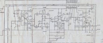
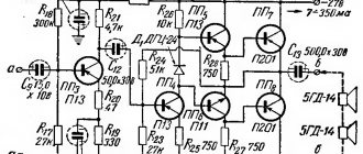
The basic initial model of the amplifier “Quad 405/405-2” is made according to the circuit shown in Fig. 7.
The original contained a table of element replaceability and permissible deviations of ratings. R2 - with a resistance of 10 Ohms, a power of 5 W - 5% separates the signal ground from the power ground. In the original, coils L1 and L2 are wound on a mandrel with a diameter of 8 mm in two layers with PEL wire 0 1...1.5 mm and have an inductance L1 - 3...3.3 μH, L2 - 22...24 μH. In Fig. 8 shows a drawing of a printed circuit board, and Fig. 9 - amplifier wiring diagram.
The author collected and tested the Hungarian (Fig. 2 [4]) and British (Fig. 7 [8]) versions with a reduced supply voltage (±30 V) and a reduced power of 45 W. When measuring the technical characteristics, the difference was minimal. In the diagram in Fig. 7, the nonlinear distortion coefficient was slightly lower than in the circuit in Fig. 2.
The author continues to work on the circuits of the “Quad 520” (power 250 W, RH - 8 Ohm) and “Quad 606” (Pout = 350 W, RH ~ 8 Ohm) models, using a bridge circuit for constructing an output stage in these designs.
Engineer K. Pribojski - conducted an experiment with the “Quad 520” using an LF357 op-amp and KD503 transistors in the output stage. Experiments have confirmed high technical characteristics with output power up to 250 W.
In 1989, the book “Functional Units of High-Quality Sound Reproduction Amplifiers” [11] was published in Russia by the authors D. Ataev and V. Bolotnikov, which contains another Russian version of the “Quad 405” amplifier, which is as close as possible to the original [9].
The author is interested in any developments of the Quad 405, as well as materials published in various literature.
The author expresses gratitude to senior researcher. II Art. Dr. Eng. M. Shaferski and senior researcher II Art. Dr. Eng. T. Strashimirov for his invaluable assistance in preparing the material for this article.
LITERATURE
- Lolov P. High-quality edge amplifier. - Radio, television, electronics, 1998, No. 11, pp. 10...13.
- 2. Reshetnikov O. Reducing distortion in power amplifiers. - Radio, 1979, No. 12, pp. 40...42.
- Radio Yearbook, 1983, P.93...101.
- Radiotechnika, 1983, No. 9 (Hungary).
- Solntsev Yu. High-quality power amplifier. - Radio, 1984, No. 5.
- Solntsev Yu. High-quality power amplifier. Returning to what was printed. - Radio, 1984, No. 12, P.44...46
- Young Constructor, 1988, No. 9,10.
- The application was prepared by A. Yanakiev
- Walker, P. J. Current dumping audio amplifier, Wireless World, 1975, Dec. (Vol. 81, 1480).
- VanderKooy, J., S. P. Lipshitz. Current dumping does it really work?, Wireless World, 1978, June (Vol. 84, 1510).
- Black, H. US Pat 1, 689, 792, 9th Oct. 1929.
- Ataev D.I., Bolotnikov V.A. Functional units of high-quality sound reproduction amplifiers. - M.: Radio and Communications, 1989.
- Quad 405. Current Dumping Amplifier. Instruction book.
Radio amateur No. 8 2001
↑ QUAD cooling system
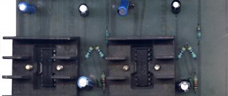
I did it this way: I cut the corner into two pieces 92 mm long, then attached them to the board and marked 2 holes in the corners of the board, drilled and screwed the corners to the boards. Next, we bend the leads of the transistors, insert them into the seats and mark the holes for the fasteners. I did this with 4 transistors on the board. Next, I drilled the corner and cut the thread. Since my corner was previously painted with something green, I sanded it on a flat surface and at the same time created an exact plane for fastening on both sides.
Then we begin to put this whole thing together: we smear the mica gasket on one side with thermal paste and apply it to the radiator with the smeared side, we smear the heat sink of the transistor and install it in the holes provided for it in the board, screw it through a flat washer to the radiator in the case of 2SD1047
.
When installing TIP42 °C,
everything is the same, only you first need to buy 4 plastic dielectric washers for TO-220 housings.
The corners carrying the VK transistors are screwed through thermal paste onto a larger radiator. Mine is not very big, but quite massive. When operating at medium power, this radiator heats up to ~60 degrees.
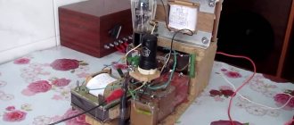
↑ Power supply
Let's take a look at the power supply. The required power supply of the original circuit is +/-40V - +/-50V. The power supply of this ULF is made according to a classic unstabilized circuit. Example of my BP:
The elements I used: • a transformer from Brig with secondary windings of 31 V and a power of about 250-300 W (by eye). Was donated by a friend Alexey, who in turn is now busy assembling this version of QUAD 405 • C1-C2 0.22uF 275V MKT • D1-D4 - SF56 • R1-R2 discharge resistors 2 kOhm 2 W • C3-C4 Main filter capacitors purchased by me on occasion in Kyiv. When I needed one tricky and rare microcircuit, that store hinted to me that they would not send a couple of microcircuits and I had to buy a couple of high-quality Nippon ChemiCon 10000uF 50V capacitors for the load. • R3-R4 current limiting resistors to indicate positive and negative power relative to the midpoint. • C5-C6 shunt capacitors WIMA 0.33uF 63V The power supply is ready. Let's start checking.
↑ First start-up and setup
It is MANDATORY to make the first switch-on with an incandescent lamp of 100-150 W 220V connected to the break in one of the power wires of the primary transformer.
My power supply has successfully started, now we connect it to the first ULF channel being tested. We don't remove the light bulb. We short-circuit the ULF input. We connect the tester to the output and measure the constant voltage at the output. In my case it turned out to be +35V, in the second channel it is similar. This is where I got upset
I started comparing it with the map of the location of the elements - everything is in order. I found the original QUAD 405-2 circuit and began searching for the error. And I found it! It was hidden in the tangled legs of TR2 2N5551. I looked at the photo of the Chinese board, it is also soldered there according to the wiring diagram. Strange... maybe the Chinese thereby protected themselves from board cloning?! Well, oh well, I changed the base with the collector of the transistor, applied power and saw 40mV on the tester screen, which is a good result.
I don’t have an oscilloscope at home, so I boldly connected the 5-GDSH-4 test speaker and sent a signal to the input. The sound is gone, the corner is heating up normally. After listening to one channel, I burst into a happy smile, and when I switched to channel 2, everything was fine there too. A correctly assembled amplifier from working parts with the required supply voltage from +/-40V to +/-50V does not require adjustment and tuning.
Circuits of the legendary Quad 405 amplifier and its clones
The circuit of the powerful Hi-Fi amplifier “Quad 405” has long been known among professionals and amateurs. In terms of its sound, it is close to tube amplifiers, but has a slightly higher harmonic distortion coefficient.
Often the harmonic distortion coefficient is incorrectly called the nonlinear distortion coefficient, which is not entirely true, since nonlinear distortion is the sum of two components - harmonic and dynamic nonlinear distortion.
It is known that modern high-power amplifiers assembled on transistors and integrated circuits have a low level of harmonic nonlinear distortion, which is reduced by introducing deep general negative feedback. It turns out that such a design of circuits, as in tube amplifiers, is “disastrous” in relation to “harmonic nonlinear distortions,” but when using transistors and microcircuits, it also allows one to minimize the coefficient of dynamic nonlinear distortions. Since the methods for reducing harmonic and dynamic nonlinear distortions are mutually opposed, usually in modern amplifiers a compromise is found, which results in the elementary conclusion of professional musicians and “listeners” that the amplifier is similar to a tube amplifier and has a very good sound.
This effect was implemented in a scheme developed by the British company Acoustical Manufacturing Company back in the mid-70s of the last century.
The first information in amateur radio Hi-Fi circles about “Quad 405” appeared some time later in [2]. The article was written by O. Reshetnikov and entitled “Reducing distortion in power amplifiers.” The circuit (Fig. 1) is structurally the same as the basic “Quad 405”, but has lower output power and low input sensitivity.
The technical characteristics of O. Reshetnikov’s amplifier are as follows:
– nominal bandwidth
with unevenness ±1 dB, Hz 20…20000;
– rated output power into 8 ohm load
and harmonic distortion coefficient 0.02%, W 30;
maximum output power at 4 ohm load, W 45;
– sensitivity at rated output power, m V 200;
– self-noise level , dB 75.
Rice. 1. Quad 405 amplifier circuit
Transistors VT9, VT12, VT15, VT16 are installed on a radiator with an area of 900 cm2 and are insulated with mica gaskets.
It is interesting that “Quad 405m and its modifications operate in class “B” mode.
At the beginning of 1983, O. Reshetnikov’s scheme with a detailed description was published in the magazine “Radio” [3].
The Hungarian amateur radio magazine “Radiotechnika” [4] published a version of “Quad 405” using the common tA709C and LM101/201/301 microcircuits, not usually used in traditional Hi-Fi equipment.
In terms of its technical characteristics, this version is closest to the English prototype:
– output power at a load of 8 ohms , W………………..100;
– harmonic distortion coefficient Kg %………0.007;
– input sensitivity for Rvih = 50 W, mV………..50.
The circuit diagram of the Hungarian version of the “Quad 405” amplifier is shown in Fig. 2,
printed circuit board - in Fig. 3, and the arrangement of elements is in Fig. 4. In Fig. Figure 5 shows the design of coils L1 ... L3.
When using a tA709C type microcircuit, resistor R9 is replaced with a jumper, and resistor R11 is excluded from the circuit. When using the LM301 microcircuit, the nominal value is R9-220 Ohm, R10-1.8 kOhm, R11 - 1.8 kOhm, and elements R19, C9, C5 are excluded from the circuit.
The following publication on the topic “Quad” appeared in the magazine “Radio” - author Yu. Solntsev [5]. The amplifier has an input sensitivity of 200 mV and an output power of 70 W into a 4 ohm load. What's new in this development is the following:
– switching on at the output of a complementary pair of powerful transistors according to the Darlington circuit;
– use of a speaker protection device.
The diagram is shown in Fig. 6. A detailed description of this scheme can be found in [5] and [6]. Instead of the K574UD1A op-amp, you can use TL071 or LF357.
This scheme with a brief description was also published in [7].
The magazine “Radio, Television” [1] published a circuit with minor changes, according to which a stereo amplifier was assembled. The design confirmed the technical parameters given in [1].
The basic initial model of the amplifier “Quad 405/405-2” is made according to the circuit shown in Fig. 7.
The original contained a table of element replaceability and permissible deviations of ratings.
R2 – with a resistance of 10 Ohms, a power of 5 W/5%, separates the signal ground from the power ground.
In the original, coils L1 and L2 are wound on a mandrel with a diameter of 8 mm in two layers with PEL wire 0 1 ... 1.5 mm and have an inductance L1 -3...3.3 μH, L2 - 22...24 μH.
Rice. 2. Circuit diagram of the Hungarian version of the amplifier “Quad 405”
Rice. 3. Printed circuit board
Rice. 4. Arrangement of elements
Rice. 5. Design of coils L1…L3
Rice. 6. Amplifier circuits of Yu. Solntsev’s version
Rice. 7. Basic initial amplifier model “Quad 405/405-2'
In Fig. 8 shows a drawing of a printed circuit board, and Fig. 9 – amplifier wiring diagram.
The author collected and tested the Hungarian (Fig. 2 [4]) and British (Fig. 7 [8]) options with a reduced supply voltage (±30 V) and reduced power - 45 W. When measuring the technical characteristics, the difference was minimal. In the diagram in Fig. 7, the nonlinear distortion coefficient was slightly lower than in the circuit in Fig. 2.
The author continues to work on the circuits of the “Quad 520” (power 250 W, RH – 8 Ohm) and “Quad 606” (P8Х = 350 W, RH – 8 Ohm) models, using in these designs a bridge circuit for constructing an output stage.
Engineer K. Pribojski conducted an experiment with the ''Quad 520” using an LF357 op-amp and KD503 transistors in the output stage. Experiments confirmed high technical characteristics at Pout <250 W.
In 1989, a book by the authors D. Ataev and V. Bolotnikov “Functional components of amplifiers for high-quality sound reproduction” [11] was published in Russia, where another Russian version of the amplifier ''Quad 405'' is given, which is as close as possible to the original [9].
Rice. 8. PCB drawing
Rice. 9. Wiring diagram
The author of the article is D. Kostov. The article was published in RL, No. 8, 2001.
Tweet Like
- Previous post: Two electronic sirens (with printed circuit board)
- Next entry: Electronic stereo tone control unit with push-button control on KR174XA54
- Preventing Excessive Power Dissipation in Linear Regulators (0)
- Power regulators for a soldering iron, another diagram (0)
- About frequencies, periods, power, alternating voltages and currents and a little about signals (0)
- Power - basic concepts (0)
- AUDIO PREAMPLIFIER WITH AGC (2)
- BUFFER DEVICE WITH UNITY GAIN FOR ADC (0)
- SCHEME OF SOUND ALARM IN THE EVENT OF SHORT CIRCUIT (0)
Related posts:
↑ AC protection
Next we move on to AC protection. I applied Alexander Kotov's defense scheme. It is quite simple and reliable, although it has a drawback: different sensitivity of operation from positive and negative input voltage. With R1 and R2 equal to 33k, the circuit operates from approximately +1.5V and -2.5V. C1 and C2 are non-polar electrolytic capacitors. I have a 2A diode bridge in a housing similar to DIP. I bought separate relays for each channel with a contact current of 10A manufactured by OMRON with 12V coils and connected them in series.
The circuit is powered by a separate transformer with a 20V secondary. It is also recommended to connect the minus or plus power supply of the circuit to the normally open contact of the power-on button (relay) on the amplifier, so that when the power is turned off with the button, the protection is immediately turned off, and does not wait until the capacitors are discharged.
The delay time interval is set by capacitor C3. With a capacitance of 100 uF, the delay is about six seconds, which suits me quite well.
↑ Reviews of the QUAD 405 amplifier
I came across a review from a person after listening to the original Quod, with which I completely agree:
mummy:
I managed to get a Quad 34 and a Quad 405-2 for an audition for a while. I was quite skeptical, because before in my room, with my speakers (Naim Allae), I had not heard the so-called. vintage equipment. However, after all the manipulations done to connect (old connectors are used, such as Soviet DINs), I finally connected everything (I had to tinker a little with Naim bananas) and first turned on “Shpongle” - “Tales Of The Inexpressible”... I turned it on and caught myself only on On the 6th track “Shhpongleyes”, I finally understood what hooked me in this combination to such an extent - this extraordinary feeling of the reality of the transmission of what was happening. I got the feeling that the music around me and all this ambient at the beginning of the track was not a dream, but reality. This was followed by several more electronic groups - the effect was the same. Moreover, the feeling of the reality of what was happening did not leave me in other rooms either - I had a desire to return and “finish” the track.
QUAD 405
The circuit of the powerful HI-FI amplifier “Quad 405″ has long been known among professionals and amateurs. In terms of its sound, it is close to tube amplifiers, but has a slightly higher harmonic distortion coefficient.Often the harmonic distortion factor is incorrectly called the nonlinear distortion factor, which is not entirely true, since nonlinear distortion is the sum of two components - harmonic and dynamic nonlinear distortion.
It is known that modern high-power amplifiers, assembled on transistors and integrated circuits, have a low level of harmonic nonlinear distortion, which is reduced by introducing deep general negative feedback. It turns out that such a design of circuits, as in tube amplifiers, is “disastrous” in relation to “harmonic nonlinear distortions,” but when using transistors and microcircuits, it also allows minimizing the coefficient of dynamic nonlinear distortions. Since the methods for reducing harmonic and dynamic nonlinear distortions are mutually opposed, usually a compromise is found in modern amplifiers, which results in the elementary conclusion of professional musicians and “listeners” that the amplifier is similar to a tube amplifier and has a very good sound.
This effect was implemented in a scheme developed by the British company Acoustical Manufacturing Company back in the mid-70s of the last century.
The principle of implementation of the scheme is described in detail in [1]. The first information in amateur HI-FI circles about the “Quad 405″ appeared some time later in [2]. The article was written by O. Reshetnikov and entitled “Reducing distortion in power amplifiers.” The circuit (Fig. 1) structurally repeats the basic “Quad 405″, but has lower output power and low input sensitivity.
The technical characteristics of O. Reshetnikov’s amplifier are as follows:
nominal passband at ripple ±1 dB, 20…20000 Hz;
rated output power at a load of 8 ohms and a harmonic distortion coefficient of 0.02%, W 30;
maximum output power into a 4 ohm load, 45 W;
sensitivity at rated output power, 200 mV;
self-noise level, 75 dB.
Transistors VT9, VT12, VT15, VT16 are installed on a radiator with an area of 900 cm2 and are insulated with mica gaskets. Interestingly, the Quad 405 and its modifications operate in class B mode.
At the beginning of 1983, O. Reshetnikov’s scheme with a detailed description was published in the Radio magazine [3].
The Hungarian amateur radio magazine “Radiotechnika” [4] published a version of “Quad 405″ using common microcircuits µA709C and LM101/201/301, usually not used in traditional HI-FI equipment.
In terms of its technical characteristics, this version is closest to the English prototype:
output power at 8 Ohm load, 100 W;
harmonic distortion coefficient Kg 0.007%;
input sensitivity for Pout = 50 W, 50 mV.
The circuit diagram of the Hungarian version of the “Quad 405” amplifier is shown in Fig. 2, printed circuit board - in Fig. 3, and the arrangement of elements is in Fig. 5. In Fig. Figure 4 shows the design of coils L1…L3.
When using a microcircuit of the µA709C type, resistor R9 is replaced with a jumper, and resistor R11 is excluded from the circuit. When using the LM301 microcircuit, the nominal value of R9 is 220 Ohm, R10 is 1.8 kOhm, R11 is 1.8 kOhm, and elements R19, C9, C5 are excluded from the circuit.
The following publication on the topic “Quad” appeared in the magazine “Radio” - author Yu. Solntsev [5]. The amplifier has an input sensitivity of 200 mV and an output power of 70 W into a 4 ohm load. What's new in this development is the following:
switching on the output of a complete pair of powerful transistors according to the Darlington circuit;
use of a speaker protection device.
The diagram is shown in Fig. 6. A detailed description of this scheme can be found in [5] and [6]. Instead of the K574UD1A op-amp, you can use TL071 or LF357.
This scheme with a brief description was also published in [7].
The magazine “Radio, Television” [1] published a circuit with minor changes, according to which a stereo amplifier was assembled. The design confirmed the technical parameters given in [1].
The basic initial model of the amplifier “Quad 405/405-2″ is made according to the circuit shown in Fig. 7.
The original contained a table of element replaceability and permissible deviations of ratings. R2 - with a resistance of 10 Ohms, a power of 5 W - 5% separates the signal ground from the power ground. In the original, coils L1 and L2 are wound on a mandrel with a diameter of 8 mm in two layers with PEL wire 0 1...1.5 mm and have an inductance L1 - 3...3.3 μH, L2 - 22...24 μH. In Fig. 8 shows a drawing of a printed circuit board, and Fig. 9 - amplifier wiring diagram.
The author collected and tested the Hungarian (Fig. 2 [4]) and British (Fig. 7 [8]) versions with a reduced supply voltage (±30 V) and a reduced power of 45 W. When measuring the technical characteristics, the difference was minimal. In the diagram in Fig. 7, the nonlinear distortion coefficient was slightly lower than in the circuit in Fig. 2.
The author continues to work on the circuits of the “Quad 520″ (power 250 W, RH - 8 Ohm) and “Quad 606″ (Pout = 350 W, RH ~ 8 Ohm) models, using in these designs a bridge circuit for constructing an output stage.
Engineer K. Pribojski - conducted an experiment with the “Quad 520” using an LF357 op-amp and KD503 transistors in the output stage. Experiments have confirmed high technical characteristics with output power up to 250 W.
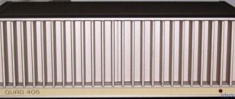
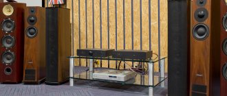
↑ Photos of the finished amplifier
And finally, a photo of the finished working, and most importantly, beautifully “singing” amplifier: