Russian Hi-End 2022: three amplifiers from Noosfera
I looked at this author’s amplifier, but it didn’t work out and they responded well. The author sent the amplifier for listening, I was literally a day late in Tyumen to listen. Here's a review:
Good night! I only had the amplifier for a few hours and my interconnects did not fit into it, because... I needed a unipolar RCA and quite long (I didn’t want to take out my equipment). We listened to this amplifier with a rather difficult load B&W 803S and a less demanding Klipsh Cornwall III. I played better at low frequencies with Klipsch than with B&W. I attach my review in a shortened version (AC B&W):
The long-awaited guest from Rostov has arrived. We meet the full amplifier Noosphere A8.
Rated output power 70W/8Om. This is almost 3 times less than my Meridian 557 PA. And it is 2 times lower in height, but let’s not rush. They greet you by their clothes, and...
Let's connect. The attenuator clicks noticeably when setting the volume. If you listen to music quietly, this will be noticeable.
I turn on the first disc that catches my eye and give the A8 an hour to warm up. I notice that in this mode the sound is very similar to my system.
I selected 7 discs for the test: the best recordings of TBM, FIM Test CD-4, Vivaldi's Alpha Disc, CCR, Deep Purple Machine Head, Eva Cassidy, Clapton & BB King.
The amplifier got noticeably hot when I started listening. Go!
You can immediately hear excellent resolution in the midrange; There is both punch and a clear, undistorted attack of the sound of the upper register of the piano; there are no complaints about the vocals. The cymbals on Aqua Marine sounded a little harsher and the violins on track #3 of the FIM Test CD-4 were a little shriller than we would have liked. At the end of the track, I would like to soften the sound of the clarinet a little, it was a little annoying. All this, most likely, can be eliminated by selecting the correct interconnect and power cable. Unfortunately, I didn’t find one worthy for my dear guest. I needed a fairly long RCA cable, but I didn’t have one of a high standard. Balanced - please. Sorry friend!
A8 play quite cheerfully in the low frequency range. On many tracks it seems like bigger is better and not needed. However, on some recordings you can still feel the insinuating nature of the sound of this range. The amplifier is modest, as if afraid to suppress the perception of the wonderful midrange. This makes the sound seem a little brighter. I repeat, this is not always noticeable. And this is with my bad speakers.
Overall I really enjoyed my listening experience. I often caught myself thinking that I was listening to the music instead of keeping track of familiar fragments. I think that with good speakers this amplifier will open up even better. I'm sure of it!
Author's amplifier Noosfera Echo v5 + Acoustics in Moscow
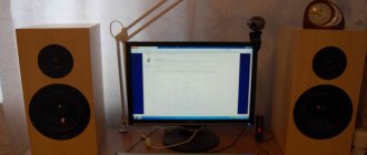
Author's amplifier Noosfera Echo v5 + Acoustics by Georgy Krylov on ScanSpeak 18W/8542 and D2905/9700, a rare, ideally combined set of Hi-End elite amplifier and the same acoustics. The equipment was developed by long-time participants of Rosshiend. The best that there is today in the Russian Federation from the author's.
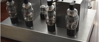
Noosfera Echo is an amplifier operating in pure class A, using a single-ended circuit, without general feedback. Like good tube circuits, it produces a clear and natural sound, but without the inherent characteristics of tubes. The power is sufficient for a variety of acoustics, except the most low-sensitive ones. There is no need to specially select acoustics, as is done “for lamps”. But to fully realize the quality of the amplifier, the acoustics must be as good as possible.
Technical parameters of the amplifier: Output impedance over the entire frequency band 0.15 Ohm. Gain band 0.2 Hz - 300 kHz at -3dB level Volume control range 99dB, step - 1dB Input impedance 10 kOhm Number of inputs 4 linear Balance adjustment +-24 dB in steps of 1 dB Dimensions 450x130x310 mm
The Echo's distortion spectrum is short and falls off quickly. Fully featured remote control, highly customizable controller with many convenient features. Control all functions from the remote control. Control from the front panel - on/off, volume, input selection. The amplifier is equipped with two remote controls. Italian-made amplifier housing, 3 mm aluminum panels, 10 mm front panel. Ideally selected components. Author's wiring. Version V5 is the latest.
Acoustics on top-end ScanSpeak Audiophiles around the world who prefer high-end acoustics and components consider Scan-Speak speakers “the best that money can buy”, and it’s hard to disagree with this.
Since its founding in 1970, Scan-Speak has used only the finest materials in its manufacturing, and all speakers are hand-assembled. The company's policy is expressed in the words “Never compromise”. Indeed, Scan-Speak does not accept compromises in the quality of its products or sound quality.
Internal - All coils are Jantzen tape, capacitors are Mundorf Supreme. Resistors MOX Mundorf. The low-pass filter looks somewhat unconventional, since the frequency response slope is formed by a coil and a notch circuit. But in principle, this is close to Linkwitz-Riley 4th order, although the midbass has a slightly steeper slope, while the tweeter has a gentle slope. This acoustics gives an amazingly smooth and correct sound. It has a very smooth frequency response, somewhat similar to ProAc but much better.
The interior is all very correct. Finishing: natural blackened ash veneer. Cool acoustic connectors.
There is a lot of bass, because these are large bookshelf speakers. They come complete with custom made metal stands. They weigh a lot. On custom steel spikes.
The entire set was assembled “for yourself”; nothing is sold separately. Selling due to complete lack of time to listen. Except that there is nothing in the profile. Upon prepayment, I will pack/send by pallet. But pickup is preferred.
Noosfera A12 User Manual. Version 6,
Transcript
1 Noosfera A12 User Manual. Version 6, Noosphere A12 Amplifier is a complete amplifier without overall negative feedback. The purpose of its creation was to develop an amplifier for home use that would provide high quality music sound when paired with the vast majority of speaker systems of any sensitivity. During development, a number of voltage amplifier circuits were prototyped, and full-scale experiments were carried out to select good-sounding output transistors. The circuit and design of the amplifier embody the following principles: 1. Short circuit: each new amplification stage will add order of harmonics. 2. Lack of general OOS, minimization of distortion due to: selection of current modes, circuit solutions, types of components, circuit design without transition capacitors. 3. Correct selection of output transistors (very important for a non-axis circuit). 4. Carefully designed nutrition. The power supply is located on the main board, close to the output stage. The rectifier bridge uses Schottky diodes that do not cause interference; the output transistors are soldered directly into the board and have short leads. The fuses are included before the rectifier and do not affect the sound. 5. The input part of the board and the voltage amplifier are powered by an increased unstabilized voltage. When the external power is turned off, the unit switches to power from the main source. 6. Thermally stable circuit. Can be connected without modification to DC voltages from +/-25V to +/-50V. 7. Carefully crafted PCB. Maximum attention was paid to the wiring of grounds, signal, power and return conductors. 8. Input and output circuits are connected using connectors, which facilitates installation of the units into the housing. 9. Selection of high quality components, without any savings. The result was a finished product in the form of a universal amplifier unit. The block consists of an assembled and configured board installed on a radiator. The unit is designed to connect power from a transformer, a separate small UN power supply, input and output signals. With a volume control at the input, the unit is one channel of amplification for a high-quality amplifier. The A12 kit includes two A12 modules, on radiators, a UN power supply, one for two channels, a transformer with completely separate windings. The controller power supply is not included in the kit and is available optionally. Controllers, relay attenuators, input selectors are produced by Maxim Volobuev. You can contact him at
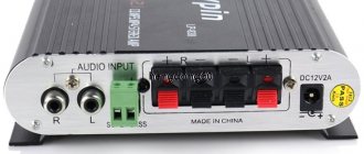
2 The block has 4 mounting holes on both sides for M3 screws with a pitch between holes of 50 mm, and is mounted directly on the bottom panel of the case. The housing should have ventilation holes at the bottom and top of the unit. Technical data: Output power when powered by a standard transformer 120W/4 Ohm. Frequency band level -0.1dB 3 Hz 25 kHz. Nonlinear distortion coefficient at average power, no more than 0.35%. Output impedance, no more than 0.45 Ohm. Radiator size 172x74x40 Height of the mounted board above the radiator 60
3 One of the amplifier options was repeated by Konstantin Tsarev, based on the Odyssey 100 U021 amplifier housing. You can read more at the link. Also at this link there is a detailed description of the circuit, written together with colleague K. Tsarev. The amplifier circuit and its brief description are given below. Structurally, like most power amplifiers, this sample consists of three stages: an input stage; voltage amplification stage; output stage. To stabilize the zero potential at the output of the amplifier, an op-amp integrator is used. The symmetrical differential input stage is built on transistors Q2 Q3, Q7 Q8 with a load on Wilson current mirrors, made on transistors Q5, Q9, Q10 in one arm and Q6, Q11, VT12 in the other. The current sources for the differential stages are made using transistors Q1 and Q4. The function of reference voltage sources is performed by red LEDs selected by voltage drop. The output transistors of the UN cascade Q10, Q11 are loaded onto resistors R16, R20, the voltage from which is supplied to the output repeater. Resistor X2 regulates the quiescent current of the output stage, and resistor X1 adjusts the sensitivity of the amplifier within small limits. The switch-on delay and DC voltage protection circuit is usually not used as unnecessary. Thanks to the symmetrical circuit, the amplifier turns on quite quietly, and turns off silently. The output stage is made of three complementary pairs of lateral field-effect transistors 2SK1058, 2SJ162 and operates in class AB with a quiescent current of mA per arm. The type of transistors used has a low slope when compared with vertical field-effect and bipolar transistors. This feature, on the one hand, determines the relatively high output resistance of the amplifier (about 0.4 Ohms with three pairs of transistors). On the other hand, the low slope and the absence of source resistors ensure relatively smooth closing/opening of the channel when transitioning from small-signal mode A to mode AB and back, reducing switching distortion, which has a positive effect on the sound of the amplifier. Also, field-effect output transistors do not have the saturation effect characteristic of bipolar transistors at maximum amplitudes. This output stage was compared with a similar stage on vertical field-effect transistors IRFP240/9240 and with a triple output stage (three repeater stages) on bipolar MJL21193/21194 and was chosen based on the subjective impression of better sound.
4 Led1 R1 47k Led2 IN- IN+ GND R2 100 R3 Q1 BC560 Q2 BC560C Q3 BC550C 2 Q4 BC mA R4 330 R5 8.2k R R7 150 R8 8.2k R9 330 R R11 R12 R C1 1n C2 1n Q5 BC560 Q6 BC550 C3 1n C4 1n R14 R15 C5 0.01u RR C6 0.1u Q7 BC560C Q8 BC550C C7 47u C8 47u R18 C9 470u C10 470u R19 4.7k R20 4.7k 3 X Q9 BC560 Q10 MJE350 Q11 MJE340 Q12 BC550 2 RXR mA 2 R27 1k C11 0.1u D1 M1 2SK1058 R23 1k R24 1k R25 1k R26 1k R28 1k 1 M2 2SJ162 3MegR D2 C12 0.3u M3 2SK1058 M4 2SJ162 C13 0.3u R30 3Meg C14 220u C15 220u M5 2SK1058 M6 2SJ162 RL 4 D3 C16 1n C u C u D4 1N4148 C u R31 3k 0.5W X3 3 2 R32 3k 0.5W D5 1N965A 15V C20 47u C2147u R33 47k X4 5 6 D6 1N965A 15V R34 47k 7 R35 47k ~33 GND ~33 D7 SR510 D9 SR510 D8 SR510 D1 0 SR GND Sink A12.01 X1 OUT
5 Installation of blocks into the housing. Basically, the following layout schemes have developed. The choice of layout depends on the size of the housing. You can come up with your own layout, for example, for a three-channel amplifier (two fronts plus a center channel). One channel A12 is suitable for use as a subwoofer amplifier, provided it is switched to deep OOOS mode. This is easy to do.
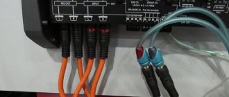
6 A drawing of the cutouts in the bottom panel of the case for installing the A12 unit is shown below. The KIT kit includes: a transformer with an overall power of 350W and low induction. Designed to connect two A8 units and a two-channel power supply for UN. UN power supply for two A8 channels (figure below). fasteners for BP UN and A8 blocks. mating parts of all used connectors, incl. power and acoustic. A detachable cable is used to connect the power supply unit (photo on the left) to the amplifier board. The photo above on the right shows both ends of it with numbering on the connectors. If the numbering of the conductors is observed (see the color of the conductors in the figure), the power polarity will be correct when connected to either end of the cable. The BP UN has two additional two-pin output connectors designed for connecting indicator LEDs. The polarity is indicated by a + sign, the output current is about 1.6 ma. Can be left unconnected.
7 Technical data of the power transformer: Name. windings Conclusions: clockwise Voltage, V Quantity. windings, pcs. Wire diameter, mm. Quantity turns Note I, Network II III IV V x31 From avg. point 2x33 With avg. point 2 0.85 2 0.45 2x170 2x170 2x185 2x185 Power supply Power supply UN Custom magnetic core 65x Power, not less than 350W. Induction at 220V 1.2 T. No-load current 7-9 mA (Sanwa 510A True RMS multimeter). Outer diameter 130 mm. Inner diameter 30 mm (compound, hole for M8 bolt). Height 65 mm. Weight, about 3.5 kg. Phase designation L. Neutral designation N. The midpoints of the windings are output to terminals 4, 7, 10, 13, clockwise (see table). The diagram of all connections to the Noosfera A12 board is shown in the figure. The input jack receives the signal from the volume control or (if using a preamplifier) from the RCA input jacks. The OUT GND connectors are connected to the terminals for connecting acoustics. OUT is red terminal, GND is black. This is the amplifier output. The secondary windings II and III of the transformer are connected to the ~33V GND - ~33V connectors. This is the power supply for the amplifier. The transformer may be marked as Connector +46V GND - -46V is used to connect a separate increased supply voltage from the power supply of the voltage amplifier. The power supply unit UN is connected to the windings of the transformer VI and V. They are marked on the transformer as
8 Requirements for connectors and their installation. The minimum requirements for connectors boil down to the exclusion of steel (we check with a magnet) and aluminum conductive (there are!) parts in acoustics connectors, RCA inputs and the network connector. As practice has shown, the quality of signal transmission in cables largely depends on the conductor and cable design, and the connectors (subject to the minimum requirements) have a less noticeable effect. However, high-quality connectors are welcome. Alternatively, you can use relatively inexpensive Cardas. If the back panel is steel, then it is necessary to make cuts between the speaker connectors, and between the inputs of the right and left channels, as shown in the figure. The RCA input jacks must be isolated from the amplifier housing. The grounds of the input connectors are combined on the “lower” pins of the volume control. This ground point is connected to the amplifier housing. Radiators are attached directly to the bottom panel of the case. The boards are circuit-connected to the radiator with a 100 Ohm resistor to eliminate the ground loop. Volume control, selector. I recommend the volume control Att7 according to the scheme of A. Nikitin, developed and produced by M. Volobuev aka Antecom. What wires should I use to mount the amplifier? I adhere to the following rules in my designs so as not to reduce the overall quality of the amplifiers. Input conductors. The best option is specially made from monocore with a diameter of 0.8 mm. The insulation is cotton cordel, then a cotton shirt, then Teflon, which provides sealing or at least low air exchange. There may be heat shrink on top. Options are simpler: a conductor of the same diameter in varnish insulation; conductor made of category 6 UTP cable in native polyethylene insulation. Category 5 UTP conductor is not suitable: it is always of lower quality and too thin. MGTF conductors and the like are not suitable. They are multi-stranded, the veins are very small. The sound with them is simpler and rougher. Silver-plated copper conductors are far from neutral, but they can be added to taste. Insulation. Any conductors in PVC insulation are strictly unsuitable, incl. in combination with silk. The silk there is artificial.
9 In general, any insulation that turns black when heated with a soldering iron, emits an unpleasant odor and smoke, is not suitable for audio conductors. Suitable insulation: polyethylene, polypropylene, varnish (various), fluoroplastic. The best insulator is air. If possible, preference should be given to thick “monocore” conductors. With them, the sound turns out to be more collected and energetic, and does not crumble into separate sounds. If the copper conductor is of good quality, and the insulation is also good, then the detail of such conductors is also good. Acoustic conductors. The best option is specially manufactured. An acceptable option is several thick conductors folded together in varnish insulation. The total cross-section is 2.2 to 3.5 square millimeters. It is very undesirable to subject these conductors to severe mechanical deformation. Their sound becomes worse and does not recover quickly unless special annealing is used. The same applies to input conductors. You can also use various “acoustic” conductors, but it is advisable to avoid multi-core ones. The insulation requirements are exactly the same as for the input conductors. Direction. The sound of any conductor depends on its direction of connection. The easiest way to determine this direction is to connect the conductor to the break of the speaker cable (one of its cores). A conductor in the “right” direction sounds clearer, the sound is richer, the timbres are more varied, the after-sounds of instruments and vocals are longer. Choose the soundtrack you want to test carefully. The conductors in the cable are oriented in opposite directions. So, as shown below: Start (+) amplifier terminal End (+) speaker terminal. End (-) amplifier terminal Beginning (-) acoustics terminal. That is, the conductors must form a ring broken by the load. The same rule applies to input conductors. The load is the volume control, and for the conductors after it the amplifier input. The input conductors in the cable can be loosely twisted together, leaving some distance between them. You will get two spirals nested inside each other. The weekends can also be twisted or laid side by side. It is better to take a little more distance between them than for the entrance ones. Network phasing in the system. The transformer that the kit is equipped with is marked with the network winding - L (phase) and N (zero). The amplifier's network connector and network cable must be connected so that the network phase falls into place, and zero too. This can be checked with a phase detector (screwdriver with a neon light bulb). When the case is metal, then with correct phasing, the neon light of the phase detector does not burn when the phase detector touches it. Turn the plug over and it will light up, maybe dimly. The second way is to check the voltage between the amplifier body and the network zero; first you need to find the zero with a phase detector. To do this, you need a simple “digital” tester, connected to measure alternating voltage. If the phasing is correct, the voltage will be minimal; if it is incorrect, it will be greater. We turn on the amplifier, measure, turn off, turn the plug over, measure again. We find the desired position and leave it there.
10 All cables must be disconnected during testing, except for the network cable. Next, we check all system components, for example the CD player, in the same way. After that, we connect everything with interconnect cables. * * * Questions can be asked by e-mail Reviews about the operation of the amplifier are posted on the website at Igor Vinogradsky aka IGVIN Rostov-on-Don.