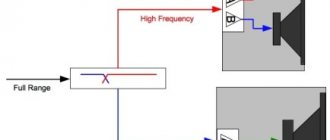
An audio amplifier is a device where the signal passes through series-connected stages. Troubleshooting is carried out using a fairly simple algorithm, so the question of how to repair an audio amplifier with your own hands is not too difficult. The only condition is the availability of measuring equipment. A conventional tester can detect some defects, and the presence of measuring equipment such as an oscilloscope and an audio frequency generator will allow you to repair the device efficiently and quickly.
Discount cards
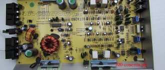
Car amplifiers are important elements of an audio equipment kit. Despite the fact that modern technology is of high quality, even the most reliable equipment can break down and fail, and then you will need car amplifier repair in Moscow. Before ordering this service, you should carefully select a specialist and compare prices - the cost must be reasonable and adequate.
WHAT YOU SHOULD PAY ATTENTION TO WHEN CHOOSING A SERVICE CENTER FOR AUTOMOBILE EQUIPMENT REPAIR:
- Work with various equipment. Experienced AS-REMONT specialists can easily take on the troubleshooting of domestic and foreign equipment, so you can be sure that your model will be familiar to them, and the specialists will easily fix all problems.
- Repair times. Music in the car is an important part of everyday life. At AS-REMONT you won’t have to wait long for repairs. Experienced specialists will do everything as quickly as possible, and within 1-3 days you will be able to enjoy your favorite songs in the cabin at full volume.
- The simplest breakdown of audio equipment is damage to the cord or power supply. In this case, there is no need to disassemble the amplifier - repair of audio amplifiers will be carried out as quickly as possible. If the device cannot be repaired, a preliminary diagnosis is carried out and the client is notified about this.
- Replacement of burnt or failed parts . If it is necessary to replace an element, experienced AS-REMONT craftsmen will order the required part themselves and install it without difficulty.
- Real prices. The cost of repairing audio equipment should be affordable and set within reasonable limits. AS-REMONT offers repairs at the lowest prices in Moscow.
| UMZCH repair is almost the most common question asked on amateur radio forums. And at the same time – one of the most difficult. Of course, there are “favorite” faults, but in principle, any of several dozen, or even hundreds of components that make up the amplifier can fail. Moreover, there are a great many UMZCH circuits. Create a discussion about an article on the forum | Author: Falconist |
Of course, it is not possible to cover all cases encountered in repair practice, however, if you follow a certain algorithm, then in the vast majority of cases it is possible to restore the functionality of the device in a very reasonable time. This algorithm was developed by me based on my experience in repairing about fifty different UMZCHs, from the simplest ones, for a few watts or tens of watts, to concert “monsters” of 1...2 kW per channel, most of which were received for repair without circuit diagrams.
The main task of repairing any UMZCH is to localize the failed element, which entails the inoperability of both the entire circuit and the failure of other cascades. Since in electrical engineering there are only 2 types of defects:
- Presence of contact where it should not be;
- Lack of contact where it should be
then the “ultimate task” of repair is to find a broken or torn element. And to do this, find the cascade where it is located. Next is “a matter of technology.” As doctors say: “The correct diagnosis is half the treatment.”
List of equipment and tools necessary (or at least highly desirable) for repairs:
- Screwdrivers, side cutters, pliers, scalpel (knife), tweezers, magnifying glass - i.e., the minimum required set of ordinary installation tools.
- Tester (multimeter).
- Oscilloscope.
- A set of incandescent lamps for various voltages - from 220 V to 12 V (2 pcs.).
- Low-frequency sinusoidal voltage generator (highly desirable).
- Bipolar regulated power supply 15...25(35) V with output current limitation (highly desirable).
- Capacitance and Equivalent Series Resistance (ESR) meter for capacitors (highly desirable).
- And finally, the most important tool is a head on your shoulders (required!).
Let's consider this algorithm using the example of repairing a hypothetical transistor UMZCH with bipolar transistors in the output stages (Fig. 1), which is not too primitive, but not very complicated either. This scheme is the most common “classic of the genre”. Functionally, it consists of the following blocks and nodes:
- bipolar power supply (not shown);
- input differential stage on transistors VT2, VT5 with a current mirror on transistors VT1 and VT4 in their collector loads and a stabilizer of their emitter current on VT3;
- voltage amplifier on VT6 and VT8 in cascode connection, with a load in the form of a current generator on VT7;
- quiescent current thermal stabilization unit on transistor VT9;
- unit for protecting output transistors from overcurrent on transistors VT10 and VT11;
- current amplifier based on complementary triplets of transistors connected according to a Darlington circuit in each arm (VT12VT14VT16 and VT13VT15VT17).
Rice. 1.
- The first point of any repair is an external inspection of the subject and sniffing it (!). This alone sometimes allows us to at least guess the essence of the defect. If it smells burnt, it means something was clearly burning.
- Checking the presence of mains voltage at the input: the mains fuse has blown, the fastening of the power cord wires in the plug has become loose, there is a break in the power cord, etc. The stage is the most banal in its essence, but at which the repair ends in approximately 10% of cases.
- We are looking for a circuit for the amplifier. In the instructions, on the Internet, from acquaintances, friends, etc. Unfortunately, more and more often lately it has been unsuccessful. If we didn’t find it, we sighed heavily, sprinkled ashes on our heads and started drawing a diagram on the board. You can skip this step. If the result doesn't matter. But it's better not to miss it. It’s boring, long, disgusting, but - “It’s necessary, Fedya, it’s necessary...” ((C) “Operation “Y”...).
- We open the subject and carry out an external inspection of its “gibles”. Use a magnifying glass if necessary. You can see destroyed housings of semi-automatic devices, darkened, charred or destroyed resistors, swollen electrolytic capacitors or electrolyte leaks from them, broken conductors, printed circuit board tracks, etc. If one is found, this is not yet a reason for joy: destroyed parts may be the result of the failure of some “flea” that is visually intact.
- Checking the power supply. We unsolder the wires going from the power supply to the circuit (or disconnect the connector, if there is one). We take out the mains fuse and solder a 220 V (60…100 W) lamp to the contacts of its holder. It will limit the current in the primary winding of the transformer, as well as the currents in the secondary windings.
Turn on the amplifier. The lamp should blink (while the filter capacitors are charging) and go out (a faint glow of the filament is allowed). This means that K.Z. There is no mains transformer on the primary winding, and there is no obvious short circuit. in its secondary windings. Using a tester in alternating voltage mode, we measure the voltage on the primary winding of the transformer and on the lamp. Their sum must be equal to the network one. We measure the voltage on the secondary windings. They must be proportional to what is actually measured on the primary winding (relative to the nominal). You can turn off the lamp, replace the fuse and plug the amplifier directly into the network. We repeat the voltage check on the primary and secondary windings. The relationship (proportion) between them should be the same as when measuring with a lamp.
The lamp burns constantly at full intensity - this means we have a short circuit. in the primary circuit: we check the integrity of the insulation of the wires coming from the network connector, the power switch, the fuse holder. We unsolder one of the leads going to the primary winding of the transformer. The lamp goes out - most likely the primary winding (or interturn short circuit) has failed.
The lamp burns constantly at incomplete heat - most likely, there is a defect in the secondary windings or in the circuits connected to them. We unsolder one wire going from the secondary windings to the rectifier(s). Don't get confused, Kulibin! So that later there will be no excruciating pain from incorrect soldering back (mark, for example, using pieces of adhesive masking tape). The lamp goes out, which means everything is in order with the transformer. It’s burning – we sigh heavily again and either look for a replacement or rewind it.
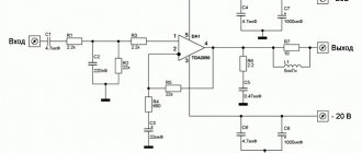
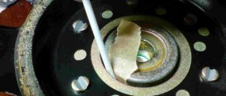
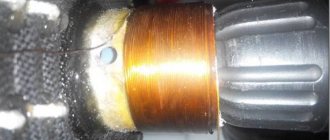
6. It was determined that the transformer is in order, and the defect is in the rectifiers or filter capacitors. We test the diodes (it is advisable to unsolder them under one wire going to their terminals, or unsolder them if it is an integral bridge) with a tester in ohmmeter mode at the minimum limit. Digital testers often lie in this mode, so it is advisable to use a pointer device. Personally, I have been using a beeper for a long time (Fig. 2, 3). Diodes (bridge) are broken or broken - we replace them. Whole – “ring” filter capacitors. Before measurement, they must be discharged (!!!) through a 2-watt resistor with a resistance of about 100 Ohms. Otherwise, you may burn the tester. If the capacitor is intact, when it closes, the needle first deflects to the maximum, and then quite slowly (as the capacitor charges) “creeps” to the left. We change the connection of the probes. The arrow first goes off scale to the right (there is a charge left on the capacitor from the previous measurement) and then creeps to the left again. If you have a capacitance and ESR meter, then it is highly advisable to use it. We replace broken or broken capacitors.
| Rice. 2. Diode tester circuit | Rice. 3. Diode tester |
7. The rectifiers and capacitors are intact, but is there a voltage stabilizer at the output of the power supply? No problem. Between the output of the rectifier(s) and the input(s) of the stabilizer(s), we turn on the lamp(s) (chain(s) of lamps) to a total voltage close to that indicated on the body of the filter capacitor. The lamp lights up - there is a defect in the stabilizer (if it is integral), or in the reference voltage generation circuit (if it is on discrete elements), or the capacitor at its output is broken. A broken control transistor is determined by ringing its terminals (unsolder it!).
8. Is everything okay with the power supply (the voltage at its output is symmetrical and nominal)? Let's move on to the most important thing - the amplifier itself. We select a lamp (or strings of lamps) for a total voltage not lower than the rated one from the power supply output and through it (them) we connect the amplifier board. Moreover, preferably to each of the channels separately. Turn it on. Both lamps came on - both arms of the output stages were broken. Only one - one of the shoulders. Although not a fact.
9. The lamps are not lit or only one of them is lit. This means that the output stages are most likely intact. We connect a 10…20 Ohm resistor to the output. Turn it on. The lamps should blink (there are usually also power supply capacitors on the board). We apply a signal from the generator to the input (the gain control is set to maximum). The lamps (both!) lit up. This means that the amplifier amplifies something (although it wheezes, vibrates, etc.) and further repair consists of finding an element that takes it out of mode. More on this below.
10. For further testing, I personally do not use the amplifier’s standard power supply, but use a 2-polar stabilized power supply with a current limit of 0.5 A. If there is none, you can also use the amplifier’s power supply, connected, as indicated, through incandescent lamps . You just need to carefully insulate their bases so as not to accidentally cause a short circuit and be careful not to break the flasks. But an external power supply is better. At the same time, the current consumption is also visible. A well-designed UMZCH allows supply voltage fluctuations within fairly wide limits. We don’t need its super-duper parameters when repairing, just its performance is enough.
11. So, everything is in order with the power supply. Let's move on to the amplifier board (Fig. 4). First of all, you need to localize the cascade(s) with broken/broken component(s). For this, it is highly advisable to have an oscilloscope. Without it, the effectiveness of repairs drops significantly. Although you can also do a lot of things with a tester. Almost all measurements are made without load (idling). Let us assume that at the output we have a “skew” of the output voltage from several volts to the full supply voltage.
12. First, we turn off the protection unit, for which we unsolder the right terminals of diodes VD6 and VD7 from the board (in my practice there were three cases when the cause of inoperability was the failure of this particular unit). We look at the voltage output. If it has returned to normal (there may be a residual imbalance of several millivolts - this is normal), we call VD6, VD7 and VT10, VT11. There may be breaks and breakdowns of passive elements. We found a broken element - we replace and restore the connection of the diodes. Is the output zero? Is the output signal (when a signal from the generator is applied to the input) present? The renovation is complete.
Rice. 4.
Has anything changed with the output signal? We leave the diodes disconnected and move on.
13. We unsolder from the board the right terminal of the OOS resistor (R12 together with the right terminal C6), as well as the left terminals R23 and R24, which we connect with a wire jumper (shown in red in Fig. 4) and through an additional resistor (without numbering, about 10 kOhm) connect to the common wire. We bridge the collectors VT8 and VT7 with a wire jumper (red), excluding capacitor C8 and the quiescent current thermal stabilization unit. As a result, the amplifier is separated into two independent units (input stage with a voltage amplifier and output follower stage), which must work independently.
Let's see what we get as a result. Is the voltage imbalance still there? This means that the transistor(s) of the “skewed” shoulder are broken. We unsolder, call, replace. At the same time, we also check passive components (resistors). The most common type of defect, however, I should note that very often it is a consequence of the failure of some element in the previous cascades (including the protection unit!). Therefore, it is still advisable to complete the following points.
Is there any skew? This means that the output stage is presumably intact. Just in case, we apply a signal from the generator with an amplitude of 3...5 V to point “B” (connections of resistors R23 and R24). The output should be a sinusoid with a well-defined “step”, the upper and lower half-waves of which are symmetrical. If they are not symmetrical, it means that one of the transistors of the arm where it is lower has “burned out” (lost parameters). We solder and call. At the same time, we also check passive components (resistors).
Is there no output signal at all? This means that the power transistors of both arms flew out “through and through”. It's sad, but you'll have to unsolder everything and ring and then replace it.
Breakage of components is also possible. Here you really need to turn on the “8th instrument”. We check, replace...
14. Have you achieved symmetrical repetition at the output (with a step) of the input signal? The output stage has been repaired. Now you need to check the functionality of the quiescent current thermal stabilization unit (transistor VT9). Sometimes there is a violation of the contact between the motor of the variable resistor R22 and the resistive track. If it is connected in the emitter circuit, as shown in the diagram above, nothing bad can happen to the output stage, because at the point of connection of the VT9 base to the divider R20–R22R21, the voltage simply increases, it opens slightly more and, accordingly, the voltage drop between its collector and emitter decreases. A pronounced “step” will appear in the idle output.
However (very often), a tuning resistor is placed between the collector and the VT9 base. An extremely foolproof option! Then, if the motor loses contact with the resistive track, the voltage at the base of VT9 decreases, it closes and, accordingly, the voltage drop between its collector and emitter increases, which leads to a sharp increase in the quiescent current of the output transistors, their overheating and, naturally, thermal breakdown. An even more stupid option for performing this cascade is if the VT9 base is connected only to the variable resistor motor. Then, if contact is lost, anything can happen on it, with corresponding consequences for the output stages.
If possible, it is worth rearranging R22 into the base-emitter circuit. True, in this case, the regulation of the quiescent current will become distinctly nonlinear depending on the angle of rotation of the engine, but IMHO this is not such a big price to pay for reliability. You can simply replace the VT9 transistor with another one, with the opposite type of conductivity, if the layout of the tracks on the board allows it. This will not affect the operation of the thermal stabilization unit in any way, because it is a two-terminal network and does not depend on the type of conductivity of the transistor.
Testing this cascade is complicated by the fact that, as a rule, connections to collectors VT8 and VT7 are made with printed conductors. You will have to lift the legs of the resistors and make connections with wires (Figure 4 shows wire breaks). Between the positive and negative supply voltage buses and, accordingly, the collector and emitter of VT9, resistors of approximately 10 kOhm are connected (without numbering, shown in red) and the voltage drop across transistor VT9 is measured when the trimmer resistor R22 is rotated. Depending on the number of repeater cascades, it should vary within approximately 3...5 V (for “triples”, as in the diagram) or 2.5... 3.5 V (for “twos”).
15. So we got to the most interesting, but also the most difficult - the differential cascade with a voltage amplifier. They only work together and it is fundamentally impossible to separate them into separate nodes.
We bridge the right terminal of the OOS resistor R12 with the collectors VT8 and VT7 (point “ A ”, which is now its “output”). We get a “stripped-down” (without output stages) low-power op-amp, which is fully operational at idle (without load). We apply a signal with an amplitude from 0.01 to 1 V to the input and see what happens at point A. If we observe an amplified signal of a form symmetrical relative to the ground, without distortion, then this cascade is intact.
16. The signal is sharply reduced in amplitude (low gain) - first of all, check the capacitance of the capacitor(s) C3 (C4, since, to save money, manufacturers very often install only one polar capacitor for a voltage of 50 V or more, hoping that reverse polarity it will still work, which is not the case). When it dries out or breaks down, the gain decreases sharply. If there is no capacitance meter, we simply check by replacing it with a known good one.
The signal is skewed - first of all, check the capacitance of capacitors C5 and C9, which shunt the power buses of the preamplifier section after resistors R17 and R19 (if these RC filters exist at all, since they are often not installed).
The diagram shows two common options for balancing the zero level: with resistor R6 or R7 (there may, of course, be others), if the contact of the motor is broken, the output voltage can also be skewed. Check by rotating the engine (although if the contact is “completely broken”, this may not give a result). Then try to bridge their outer terminals with the output of the engine using tweezers.
There is no signal at all - we look to see if it is even present at the input (break in R3 or C1, short circuit in R1, R2, C2, etc.). Just first you need to unsolder the VT2 base, because... the signal on it will be very small and look at the right terminal of resistor R3. Of course, the input circuits may differ greatly from those shown in the figure - include the “8th instrument”. Helps.
17. Naturally, it is not realistic to describe all possible cause-and-effect variants of defects. Therefore, further I will simply outline how to check the nodes and components of this cascade.
Current stabilizers VT3 and VT7. Breakdowns or breaks are possible in them. The collectors are desoldered from the board and the current between them and the ground is measured. Naturally, you first need to calculate what it should be based on the voltage at their bases and the values of the emitter resistors. (NB! In my practice, there was a case of self-excitation of the amplifier due to an excessively large value of the resistor R10 supplied by the manufacturer. Adjusting its value on a fully operating amplifier helped - without the above-mentioned division into stages).
You can check transistor VT8 in the same way: if you jumper the collector-emitter of transistor VT6, it also stupidly turns into a current generator.
The transistors of the differential cascade VT2V5T and the current mirror VT1VT4, as well as VT6 are checked by their continuity after desoldering. It is better to measure the gain (if the tester has such a function). It is advisable to choose ones with the same gain factors.
18. A few words “off the record.” For some reason, in the overwhelming majority of cases, transistors of greater and greater power are installed in each subsequent stage. There is one exception to this dependence: the transistors of the voltage amplification stage (VT8 and VT7) dissipate 3...4 times more power than the pre-driver VT12 and VT23 (!!!). Therefore, if possible, they should be immediately replaced with medium power transistors. A good option would be KT940/KT9115 or similar imported ones.
19. Quite common defects in my practice were non-soldering (“cold” soldering to the tracks/“spots” or poor servicing of the leads before soldering) of component legs and broken leads of transistors (especially in a plastic case) directly near the case, which were very difficult to see visually . Shake the transistors, carefully observing their terminals. As a last resort, unsolder and solder again.
If you have checked all the active components, but the defect remains, you need (again, with a heavy sigh), remove at least one leg from the board and check the ratings of the passive components with a tester. There are frequent cases of breaks in permanent resistors without any external manifestations. Non-electrolytic capacitors, as a rule, do not break through/break, but anything can happen...
20. Again, based on repair experience: if darkened/charred resistors are visible on the board, and symmetrically in both arms, it is worth recalculating the power allocated to it. In the Zhytomyr amplifier “Dominator”, the manufacturer installed 0.25 W resistors in one of the stages, which regularly burned (there were 3 repairs before me). When I calculated their required power, I almost fell out of my chair: it turned out that they should dissipate 3 (three!) watts...
21. Finally, everything worked... We restore all the “broken” connections. The advice seems to be the most banal, but how many times is it forgotten!!! We restore in the reverse order and after each connection we check the amplifier for functionality. Often, a step-by-step check seemed to show that everything was working properly, but after the connections were restored, the defect “crept out” again. Lastly, we solder the diodes of the current protection cascade.
22. Set the quiescent current. Between the power supply and the amplifier board we turn on (if they were turned off earlier) a “garland” of incandescent lamps at the corresponding total voltage. We connect an equivalent load (4 or 8 ohm resistor) to the UMZCH output. We set the trimmer resistor R22 to the lower position according to the diagram and apply a signal to the input from a generator with a frequency of 10...20 kHz (!!!) of such an amplitude that the output signal is no more than 0.5...1 V. At such a level and frequency of the signal a “step” is clearly visible, which is difficult to notice at a large signal and low frequency. By rotating the R22 engine we achieve its elimination. In this case, the filaments of the lamps should glow a little. You can also monitor the current with an ammeter by connecting it in parallel with each garland of lamps. Don’t be surprised if it differs noticeably (but no more than 1.5…2 times more) from what is indicated in the setup recommendations - after all, what’s important to us is not “following the recommendations,” but the sound quality! As a rule, in “recommendations” the quiescent current is significantly overestimated in order to guarantee the achievement of the planned parameters (“at worst”). We bridge the “garlands” with a jumper, increase the output signal level to a level of 0.7 from the maximum (when the amplitude limitation of the output signal begins) and let the amplifier warm up for 20...30 minutes. This mode is the most difficult for the transistors of the output stage - the maximum power is dissipated on them. If the “step” does not appear (at a low signal level), and the quiescent current has increased no more than 2 times, we consider the setup complete, otherwise we remove the “step” again (as indicated above).
23. We remove all temporary connections (don’t forget!!!), assemble the amplifier completely, close the case and pour a glass, which we drink with a feeling of deep satisfaction for the work done. Otherwise it won't work!
Of course, this article does not describe the nuances of repairing amplifiers with “exotic” stages, with an op-amp at the input, with output transistors connected with an OE, with “double-deck” output stages, and much more...
Therefore TO BE CONTINUED ...
PRICE OF CAR AMPLIFIER REPAIR IN THE “AS-REMONT” WORKSHOP
The cost of repairing a car amplifier consists of two parts. This includes the cost of the labor and the cost of the parts that need to be replaced. The principle of setting prices for subwoofer repairs in the AS-REMONT workshop is to make the repair of audio equipment as cost-effective as possible. In simple words, we guarantee that repairing from us is always more profitable than repairing it yourself or buying a new amplifier. With us, you not only save time searching for new parts or equipment, but you are also confident in the result.
| Type of repair | Repair price |
| Repair of monoblock amplifiers from 500W | from 2000 |
| Repair of monoblock amplifiers from 800W | from 2500 |
| Repair of monoblock amplifiers from 1000W | from 3000 |
| Repair of monoblock amplifiers from 1200W | from 3500 |
| Repair of monoblock amplifiers from 2000W and above | from 4500 |
| Repair of two/four channel amplifiers from 100w | from 1000 |
| Repair of two/four channel amplifiers from 200w | from 1500 |
| Repair of two/four channel amplifiers from 400w | from 2000 |
| Repair of two/four channel amplifiers from 500w and above | from 3500 |
| Repair of five channel amplifiers | from 2300 |
| Prevention of car amplifiers | from 1100 |
| Amplifier tuning (making improvements, increasing power) | from 1500 |
| Minor repairs | from 1000 |
Amplifier path
The next step is to check the output stage. A common malfunction is the breakdown of power terminal transistors. If the device fails during operation, you need to touch the housings or heatsinks of the output semiconductor devices with your finger. Strong heating of the radiator indicates that the transistor is broken. Using the tester, you can easily check the base-emitter and base-collector junctions. If there is any doubt, it is better to remove the transistors from the board. In order to properly repair an audio amplifier, one tester is not enough. To work you will need a low frequency generator and an oscilloscope.
If the power supply and output transistors are working properly, you need to look for defects in the pre-final and preliminary stages. To do this, a signal from a generator with a frequency of 800 Hz-1 kHz and an amplitude of 100 mV must be sequentially applied to the cascades of the audio frequency unit and the passage of the signal through the speaker system must be controlled. When repairing structures with high output power, you need to use an equivalent load instead of speakers, and monitor the signal with an oscilloscope.
Designs assembled on specialized integrated circuits do not have discrete elements. The board may contain power filter capacitors and input capacitance. In this case, any diagnosis does not make sense. If the supply voltage of the device is normal and there are no breaks in the input and output circuits, then the microcircuit will have to be changed. In automotive systems, defects in printed wiring are common faults. Such violations occur among Chinese manufacturers. Poor-quality soldering is damaged by shaking and vibration, and the automotive low-frequency unit fails.
Application of sound amplifiers
Power amplifiers can be either separate independent devices, with their own control panel, or internal elements of the device, sealed into an integrated circuit. The power amplifier is the last link in the sound reinforcement chain, because of this, in the professional environment it has been given the nickname “ultimate power amplifier” or simply “terminal”.
Depending on their purpose and area of application, amplifiers can be either professional or household. Professional ones, in turn, are divided into studio, concert, broadcast, etc. The more powerful the device, the more electrical current it consumes, the correspondingly louder the sound that it can reproduce.
Household amplifiers are used in music centers, car radios, and receivers.
Stereo amplifiers are the most widely used in the field of modern sound design.
Typical faults
Before you repair, install and configure the ULF in your car, you need to understand the breakdown. It is simply impossible to consider all the faults that can be encountered in practice, since there are so many of them. The main task of repairing a sound amplification device is to restore a broken component, the failure of which led to the inoperability of the entire board.
In any electrical equipment, including amplifiers, there can be two types of faults:
- contact is present where it should not be;
- There is no contact in the place where there should be contact.
Automotive ULF microboard
Vintage, old equipment that we repair
- cassette recorder repair
- reel tape recorder repair
- CD player repair
- cassette player repair
- CD player repair
- DAT player repair
- MP3 player repair
- DVD player repair
- repair of music centers
- repair of Soviet and foreign acoustic systems (speakers, speakers)
- repair of vinyl players (gramophones)
- vinyl turntable repair
- VCR repair
- tube amplifier repair
- repair of semiconductor tube amplifiers
- Soviet amplifier repair
- repair of vintage Japanese audio equipment
- repair of old Soviet studio equipment
Basic Amplifier Settings
Now let's move on to the question - how to set up a car amplifier? There are several configuration options - for use with or without a sub.
How to properly configure the ULF without a subwoofer - first you need to set the following parameters:
- bass boost - 0 decibels;
- level - 0 (8V);
- The crossover must be set to FLAT.
After this, adjusting the audio system settings with an equalizer, the system is configured to suit your preferences. The volume must be set to maximum and turn on some track. How to set up an amplifier in a car for use with a subwoofer is also not a particularly complicated procedure.
For proper configuration, it is advisable to use the following parameters:
- Bass Boost should also be set to 0 decibels;
- the level is set to 0;
- the front crossover is set to the HP position, and the FI PASS control element must be set in the range from 50 to 80 Hertz;
- As for the rear crossover, it is set to the LP position, and the Low control must be set in the range from 60 to 100 Hertz.
It is very important to observe these parameters, since they determine the quality of the adjustment and, accordingly, the sound of the audio system. In general, the setup procedure is similar, using a level control to ensure a more harmonious sound. The sensitivity of the rear and front speakers should be adjusted to each other.
If you don’t understand anything about this, it’s better not to go there, because repairs will cost more after you burn or break.
Sorry, there are no surveys available at this time.
How to repair a car amplifier yourself
Having found the reason why the music does not turn on in the car, you can begin to eliminate the problem. When replacing a transistor that has broken down in a car amplifier, you must first check whether the fuse in the power supply is functioning and whether the diodes installed on the buses are working. If there are no problems with these elements, then the problem is in the transistor, and the solution is to replace it with a new one.
Having a special device in the form of an oscilloscope, repair work can be performed more efficiently. To do this, using the probes of the device, which are installed on the terminals present on the board, they check whether the signal is coming. If it is not there, you will have to install a new driver or replace the transistor elements.
Read about how to make high-quality sound in your car. And also about the monitor on the headrest in the car.
Capacitors rarely fail. Therefore, they look for a breakdown here as a last resort. When installing the active elements, a mica gasket is made. To ensure good heat transfer, they can be lubricated with a special paste. Both transistors and the radiator are treated with the product. After completing the process, you must remember to close the amplifier.
Frequency settings
To set the desired frequency in the car amplifier, you need to know what parameters should be set, determine a more acceptable option and choose - without a subwoofer or with it:
- Decibel level – 0.
- The range of the front crossover is from 50, not more than 80;
- rear - up to 100.
- The position of the regulator is PH and, accordingly, LP.
How the acoustics will work depends on such data.
They are responsible for the sound quality. After this, move on to the desired volume selection. Incorrectly set basic parameters will distort the sound. Published: March 21, 2022