How to make a sound amplifier?
At the initial stage of creating an amplifier, you need to find tools and buy components. The amplifier circuit is made on a printed circuit board using a soldering iron. To create microcircuits, use special soldering stations that can be bought in the store. The use of a printed circuit board allows you to make the device compact and easy to use.
Audio amplifier
Do not forget about the features of compact single-channel amplifiers based on TDA series microcircuits, the main one of which is the release of a large amount of heat. Therefore, when designing the internal structure of the amplifier, try to prevent the microcircuit from coming into contact with other parts. For additional cooling of the amplifier, it is recommended to use a radiator grille to dissipate heat. The size of the grid depends on the model of the microcircuit and the power of the amplifier. Plan in advance a place for the heat sink in the amplifier case. Another feature of making your own sound amplifier is low energy consumption. This in turn allows you to use the amplifier in a car by connecting it to a battery or on the road using battery power. Simplified amplifier models require a current voltage of only 3 volts.
Basic amplifier elements
If you are a beginner radio amateur, then for more convenient work, we recommend that you use a special computer program - Sprint Layout. With this program you can independently create and view diagrams on your computer. Please note that creating your own scheme only makes sense if you have sufficient experience and knowledge. If you are an inexperienced radio amateur, then use ready-made and proven circuits.
Below we provide diagrams and descriptions of different sound amplifier options:
Headphone amplifier
The sound amplifier for portable headphones is not very powerful, but consumes very little energy. This is an important factor for mobile amplifiers that are powered by batteries. You can also place a connector on the device for power supply via a 3 volt adapter.
Homemade headphone amplifier
To make a headphone amplifier you will need:
- Chip TDA2822 or analogue KA2209.
- Amplifier assembly diagram.
- Capacitors 100 uF 4 pieces.
- Headphone jack.
- Adapter connector.
- Approximately 30 centimeters of copper wire.
- Heat sink element (for a closed case).
Headphone amplifier circuit
The amplifier is manufactured on a printed circuit board or mounted. Do not use a pulse transformer with this type of amplifier as it may cause interference. After manufacturing, this amplifier is capable of providing powerful and pleasant sound from a phone, player or tablet. You can see another version of a homemade headphone amplifier in the video:
Sound amplifier for laptop
An amplifier for a laptop is assembled in cases where the power of the speakers built into it is not enough for normal listening, or if the speakers are out of order. The amplifier must be designed for external speakers up to 2 watts and winding resistance up to 4 ohms.
Sound amplifier for laptop
To assemble the amplifier you will need:
- Printed circuit board.
- Chip TDA 7231.
- 9 volt power supply.
- Housing for placing components.
- Non-polar capacitor 0.1 µF - 2 pieces.
- Polar capacitor 100 uF - 1 piece.
- Polar capacitor 220 uF - 1 piece.
- Polar capacitor 470 uF - 1 piece.
- Constant resistor 10 Kom - 1 piece.
- Constant resistor 4.7 Ohm - 1 piece.
- Two-position switch - 1 piece.
- Loudspeaker input jack - 1 piece.
Audio amplifier circuit for laptop
The assembly order is determined independently depending on the diagram. The cooling radiator must be of such a size that the operating temperature inside the amplifier case does not exceed 50 degrees Celsius. If you plan to use the device outdoors, then you need to make a case for it with holes for air circulation. For the case, you can use a plastic container or plastic boxes from old radio equipment. You can watch the visual instructions in the video:
Sound amplifier for car radio
This amplifier for a car radio is assembled on a TDA8569Q chip; the circuit is not complicated and very common.
Sound amplifier for car radio
The microcircuit has the following declared characteristics:
- Input power is 25 watts per channel into 4 ohms and 40 watts per channel into 2 ohms.
- Supply voltage 6-18 volts.
- Reproducible frequency range 20-20000 Hz.
For use in a car, a filter must be added to the circuit to prevent interference generated by the generator and ignition system. The microcircuit also has protection against output short circuit and overheating.
Audio amplifier circuit for car radio
Referring to the diagram presented, purchase the necessary components. Next, draw the circuit board and drill holes in it. After this, etch the board with ferric chloride. Finally, we tinker and begin to solder the components of the microcircuit. Please note that it is better to cover the power paths with a thicker layer of solder so that there are no power drawdowns. You need to install a radiator on the chip or organize active cooling using a cooler, otherwise the amplifier will overheat at increased volume. After assembling the microcircuit, it is necessary to make a power filter according to the diagram below:
Interference filter circuit
The choke in the filter is wound in 5 turns, with a wire with a cross-section of 1-1.5 mm, on a ferite ring with a diameter of 20 mm. This filter can also be used if your radio picks up interference. Attention! Be careful not to reverse the polarity of the power supply, otherwise the microcircuit will burn out instantly. You can also learn how to make an amplifier for a stereo signal from the video:
Transistor sound amplifier
As a circuit for a transistor amplifier, use the circuit below:
Transistor audio amplifier circuit
The scheme, although old, has a lot of fans, for the following reasons:
- Simplified installation due to the small number of elements.
- There is no need to sort transistors into complementary pairs.
- 10 watts of power, sufficient for living rooms.
- Good compatibility with new sound cards and players.
- Excellent sound quality.
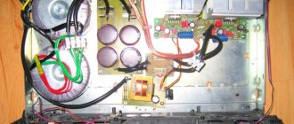
Start assembling the amplifier with power supply. Separate the two channels for stereo with two secondary windings coming from the same transformer. On the breadboard, make bridges using Schottky diodes for the rectifier. After the bridges there are CRC filters consisting of two 33,000 uF capacitors and a 0.75 Ohm resistor between them. A powerful cement resistor is needed for the filter; at a quiescent current of up to 2A, it will dissipate 3 W of heat, so it is better to take it with a margin of 5-10 W. For the remaining resistors in the circuit, a power of 2 W will be enough.
Transistor amplifier
Let's move on to the amplifier board. Everything except the output transistors Tr1/Tr2 is on the board itself. The output transistors are mounted on radiators. It is better to first set up resistors R1, R2 and R6 as trimmers, unsolder them after all adjustments, measure their resistance and solder the final constant resistors with the same resistance. The setting comes down to the following operations: using R6, it is set so that the voltage between X and zero is exactly half of the voltage +V and zero. Then, using R1 and R2, the quiescent current is set - set the tester to measure direct current and measure the current at the positive input point of the power supply. The quiescent current of an amplifier in class A is maximum and, in fact, in the absence of an input signal, all of it goes into thermal energy. For 8 ohm speakers, this current should be 1.2 A at 27 volts, which means 32.4 watts of heat per channel. Since setting the current can take several minutes, the output transistors should already be on cooling radiators, otherwise they will quickly overheat. When adjusting and lowering the resistance of the amplifier, the low-frequency cutoff frequency may increase, so for the input capacitor it is better to use not 0.5 µF, but 1 or even 2 µF in a polymer film. It is believed that this circuit is not prone to self-excitation, but just in case, a Zobel circuit is placed between point X and ground: R 10 Ohm + C 0.1 μF. Fuses must be placed both on the transformer and on the power input of the circuit. It is a good idea to use thermal paste to ensure maximum contact between the transistor and the heatsink. Now a few words about the case. The size of the case is determined by radiators - NS135-250, 2500 square centimeters for each transistor. The body itself is made of plexiglass or plastic. Having assembled the amplifier, before you start enjoying music, you need to properly distribute the ground to minimize background noise. To do this, connect the SZ to the minus of the input-output, and connect the remaining minuses to the “star” near the filter capacitors.
Transistor audio amplifier housing
Approximate cost of consumables for a transistor audio amplifier:
- Filter capacitors 4 pieces - 2700 rubles.
- Transformer - 2200 rubles.
- Radiators - 1800 rubles.
- Output transistors - 6-8 pieces, 900 rubles.
- Small elements (resistors, capacitors, transistors, diodes) cost about 2000 rubles.
- Connectors - 600 rubles.
- Plexiglas - 650 rubles.
- Paint - 250 rubles.
- Board, wires, solder about - 1000 rubles
The resulting amount is 12,100 rubles. You can also watch a video on assembling an amplifier using germanium transistors:
Tube sound amplifier
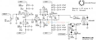
The circuit of a simple tube amplifier consists of two stages - a 6N23P pre-amplifier and a 6P14P power amplifier.
Tube amplifier circuit
As can be seen from the diagram, both cascades operate in triode connection, and the anode current of the lamps is close to the limit. The currents are adjusted by cathode resistors - 3mA for the input and 50mA for the output lamp. Parts used for a tube amplifier must be new and of high quality. The permissible deviation of resistor values can be plus or minus 20%, and the capacitances of all capacitors can be increased by 2-3 times. Filter capacitors must be designed for a voltage of at least 350 volts. The interstage capacitor must also be designed for the same voltage. Transformers for the amplifier can be ordinary - TV31-9 or a more modern analogue - TWSE-6.
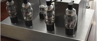
Tube sound amplifier
It is better not to install a stereo volume and balance control on the amplifier, since these adjustments can be made in the computer or player itself. The input lamp is selected from - 6N1P, 6N2P, 6N23P, 6N3P. The output pentode is 6P14P, 6P15P, 6P18P or 6P43P (with increased cathode resistor resistance). Even if you have a working transformer, it is better to use a regular transformer with a 40-60 watt rectifier to turn on the claw amplifier for the first time. Only after successful testing and tuning of the amplifier can the pulse transformer be installed. Use standard sockets for plugs and cables; to connect speakers, it is better to install 4-pin “pedals”. The housing for the claw amplifier is usually made from the shell of old equipment or system unit cases. You can watch another version of a tube amplifier in the video:
TDA7297 Specifications
- Mounting type: Through hole
- Output power: 15W
- Output signal: Differentiated
- TDA7297 supply voltage range: 6.5…18V
- Power supply: Unipolar
- Maximum potential gain: 32 dB
- Maximum power dissipation: 33W
- Product: Class AB
- Operating supply voltage: 9V, 12V, 15V
- Operating temperature range: 0…+ 70C
- Speaker impedance: 8 ohms
- Total Harmonic Distortion + Noise: 0.1%
- Output type: 2 stereo channels
- Housing type: Multiwatt-15
- Current consumption: 2A
(70.7 KiB, downloads: 2,010)