Don't dream, act!
Experiments with various preamplifiers, volume and tone controls have shown that the best sound quality is achieved with a minimum number of amplification stages, with passive controls. In this case, adjustments at the input of the power amplifier are undesirable, since they lead to an increase in the level of nonlinear distortion of the complex. This effect was recently discovered by the famous audio equipment developer Douglas Self [1].
Thus, the following structure of this part of the sound amplification path emerges: - a passive bridge regulator of low and high frequencies, - a passive volume control, - a pre-amplifier with a linear amplitude-frequency response (AFC) and minimal distortion in the operating frequency range. The obvious drawback of adjustments at the preamplifier input is that the deterioration in the signal-to-noise ratio is largely offset by the high signal level of modern sound reproduction devices.
Suggested preamplifier
Can be used in high-quality stereo audio amplifiers. The tone control allows you to adjust the amplitude-frequency response (AFC) simultaneously on two channels in two frequency regions: lower and upper. As a result, the characteristics of the room and acoustic systems, as well as the personal preferences of the listener, are taken into account.
Contents
- 1 And again a little history
- 2 Calculation of passive bridge tone controls
- 3 High quality tone control
- 4 Passive simplified tone control
- 5 Calculation of the tone control using E. Moskatov’s program
- 6 Tone control with a small range of adjustments
- 7 Making the “correct” tone control
- 8 Pre-amplifier for “student” UMZCH
- 9 Details
- 10 Installation and adjustment
- 11 Pre-amplifier characteristics:
- 12 Files
- 13 Sources mentioned
Input selector
As mentioned earlier, each RCA input is switched using the control bus (CON4 connector). To enable the input, the corresponding contact must be connected to ground (GND). In the following articles we will describe the design of the amplifier remote control unit (only if there is interest from readers!).
But it’s cheaper and easier (or at least temporarily) to use a flip switch to switch inputs. To do this you will need a single pole 5 position flip switch and a cable to connect it.
Since the audio signal is not transmitted through the cable, its length and location in the housing are not critical.
Click to enlarge
↑ And again a little history
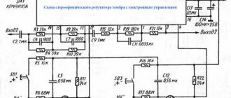
The first contender for the role of a pre-amplifier with a tone control was D. Starodub’s circuit (Fig. 1) [2]. But the design never took root in a power amplifier: careful shielding and a power supply with an extremely low ripple level (about 50 μV) were required. However, the main reason was the lack of slider variable resistors.
Rice. 1. Diagram of a high-quality tone control block
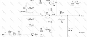
Through trial and error, I came up with a simple pre-amplifier circuit (Fig. 2), with which, however, the sound reproduction system far surpassed the sound of commercially produced equipment, at least that which my friends and acquaintances had.
Rice. 2. Schematic diagram of one pre-amplifier channel for UMZCH S. Batya and V. Sereda
The basis is taken from the circuit of the pre-amplifier of the stereophonic electrophone by Yu. Krasov and V. Cherkunov, demonstrated at the 26th All-Union Exhibition of Radio Amateur Designers. This is the left side of the circuit, including the tone controls.
The appearance of a cascade on transistors of different conductivities in the pre-amplifier (VT3, VT4) is associated with a discussion of amplifiers with the teacher of the television technology laboratory at the Department of Radio Systems A. S. Mirzoyants, with whom I worked as a student. During the work, linear cascades were needed to amplify the television signal, and Alexander Sergeevich reported that, in his experience, the best characteristics are possessed by “topsy-turvy” structures, as he put it, that is, amplifiers on transistors of the opposite structure with direct coupling. In the process of experimenting with UMZCH, I found out that this applies not only to television equipment, but also to sound reinforcement equipment. Subsequently, I often used similar circuits in my designs, including field-effect transistor - bipolar transistor pairs.
An attempt to use transistors of different structures in the first stage (composite emitter follower VT1, VT2) did not bring success, because with all the excellent characteristics (low noise level, low distortion), the circuit had a significant drawback - lower overload capacity compared to the emitter follower. Pre-amplifier specifications:
Input impedance, kOhm =
300
Sensitivity, mV =
250
Depth of tone adjustments, dB: at a frequency of 40 Hz = ±
15
at a frequency of 15 kHz = ±
15
Depth of stereo balance adjustments, dB = ±
6
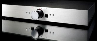
Since during the design of amplifiers new ideas arose, old designs I gave it to someone or sold it at a fixed rate of watt of output power / ruble. On one of my trips to Leningrad, I took this amplifier with me to sell it to a friend of a friend. Volodka said that this guy has a lot of Western equipment, and took the device to him for an audition. In the evening he told me the results: the young man turned on the amplifier, listened to a couple of things and was so satisfied with the sound that he paid the money without a word.
To be honest, when I found out that the comparison would take place with imported equipment, I didn’t particularly hope that the amplifier would make an impression. In addition, it was not fully completed - the top and side covers were missing.
Let's consider the circuit diagram of one pre-amplifier channel (Fig. 2). High-impedance volume (R2.1) and balance (R1.1) controls are installed at the input. From the middle terminal of resistor R2.1, through the transition capacitor C2, the sound signal is supplied to the composite emitter follower VT1, VT2, which is necessary for the normal operation of the passive tone control, made in a bridge circuit. In order to eliminate the attenuation introduced by the tone block and amplify the signal to the required level, a two-stage amplifier is installed on transistors VT3, VT4.
The preamplifier's power supply is unstabilized, from the positive arm of the power amplifier. The supply voltage is supplied to cascades VT3, VT4 through filter R17, C10, C13, and to the input emitter follower - R8, C4. The VD1 diode plays an important role: without it, it was not possible to completely eliminate the background of alternating current with a frequency of 100 Hz at the output of the power amplifier.
Structurally, the preamplifier is made in a “line”, all parts are installed on a printed circuit board, closed on top with a U-shaped screen made of steel 0.8 mm thick.
↑ Printed circuit board, layout
The printed circuit board was developed a long time ago (like the preliminary one itself) and is designed to install op-amps TL071, NE5534, OPA134
. All variable resistors for tone, volume and balance adjustments, input and output connectors are installed on one board.
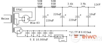
The power supply is nothing special, an unknown transic (not a torus) plus integral stabilizers. Power supply ±15 Volts and +12 Volts for the relay - from different windings of the trans. Power filter with rectifiers and stabilizers on one board. The transformer is mounted separately.
The board with the power button is located near the front panel, the 220 Volt wires go first to it, then to the fuses and to the primary of the transformer. There are no interference or background. Control of input switching and direct mode on a flip switch. In the photo this is the leftmost handle. As you can see there are a minimum of wires, the case is almost empty.
↑ Calculation of passive bridge tone controls
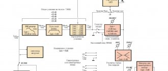
The most common is a combined circuit of low- and high-frequency regulators. As can be seen from the approximated logarithmic amplitude-frequency response (AFC) of the tone control (Fig. 3), in the mid-frequency region f0≈1000 Hz the transfer function remains unchanged, and at the edges of the frequency range it can be adjusted within certain limits.
Rice. 3. Amplitude-frequency characteristics of low- and high-frequency controllers
Typically, the rise and fall values and their control frequencies are made the same. In Fig. 3 the following designations are adopted: fnr, fvr – respectively, lower and upper regulation frequencies, fnp, fvp – lower and upper frequency response inflection frequencies, f0 – crossover frequency. In order for the low- and high-frequency controllers not to influence each other, it is necessary to fulfill the conditions of non-overlapping control zones
fnp < f0 < fvp In practical circuits of passive tone controls, the magnitude of the rise and fall of the frequency response is ±(8...20) dB, the lower control frequency is fnr = (20...80) Hz, and the upper control frequency fvp = (5...18) kHz . The disadvantage of passive tone correctors is their large intrinsic attenuation, which exceeds the full control coefficient - (16...40) dB.
Connections
Before connecting the power supply board to the preamp board, you should check the operation of the power supply. Install the mains transformer into the housing and mount its protective shield.
To obtain the declared parameters for noise and background, it is necessary to place the transformer as far as possible from the amplifier board.
It is recommended to use a toroidal transformer due to its low level of electromagnetic emissions.
It is also recommended to use a metal case for the entire structure in order to protect against external interference and radiation. Be sure to connect the chassis to ground to ensure maximum protection and safety.
To check the power supply, it is enough to measure its output voltages at terminals CON1, CON2, CON3. With a working power supply, these voltages should be +15V, -15V and +5V within ± 5%.
↑ High quality tone control
In high-quality equipment, a passive regulator of low and high frequencies, shown in Fig. 4 [3, 4].
Rice. 4. High quality passive tone control
Here the elements R1 – R3, C1, C2 form a passive frequency-dependent low-pass corrector; R5 – R7, C3, C4 – high frequency corrector. The resistor R4 connected between the regulators is an isolation that reduces the influence of the regulators on each other. Capacitor C0 serves for DC decoupling.
To calculate the tone control shown in Fig. 4, I prepared a file in the Microsoft Excel spreadsheet processor. In Fig. Figure 5 shows a screenshot of the table worksheet (without the accompanying graphic material). The initial data is entered into the cells shaded in light blue; the calculation results are placed in the table cells shaded in orange. At the beginning of the calculation, we will select the resistance values of the variable resistors R2 and R7 in kilo-ohms, then enter the range of adjustments of the low and high frequencies in decibels. As soon as we write the frequencies fнр, fвр and fн into the remaining three light blue cells, we will immediately see the results of calculating all other elements of the regulator. All that remains is to bring them to the closest values from the selected standard series E24 or E48.
Rice.
5. Calculation of the tone control using a Microsoft Excel spreadsheet Test example No. 1
. Using a spreadsheet, let's calculate a passive tone control with frequency response control limits of ±20 dB, Fig. 11.2.3 [3]. Initial data: R2=R7=100 kOhm, fnr=50 Hz, fvr=10000 Hz. We get: R1=R5=10 kOhm, R3=R6=1 kOhm, R4=10 kOhm, C1=0.032 μF, C2=0.318 μF, C3=0.0159 μF, C4=0.159 μF, C0=0.16 μF. Round to the nearest value: R1=R5=10 kOhm, R3=R6=1 kOhm, R4=10 kOhm, C1=0.033 µF, C2=0.33 µF, C3=0.015 µF, C4=0.15 µF, C0= 0.15 µF.
List of elements:
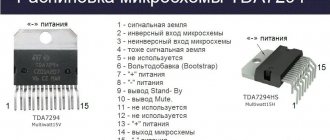
Resistors: (1% accuracy; metal film; 0.25W) R1,R2,R39,R40 = 100Ohm R3-R6,R41-R44,R78,R79 = 100kOhm R7-R12,R16,R17,R21-R24,R33, R34, R45-R50,R54,R55,R59-R62,R71,R72 = 1kOhm R13,R51 = 470Ohm R14,R15,R52,R53 = 430Ohm R18,R35,R36,R56,R73,R74 = 22kOhm R19,R20, R57,R58 = 20Ohm R25-R28,R63-R66 = 3.3kOhm R29-R32,R67-R70 = 10Ohm R37,R38,R75,R76 = 47Ohm R77 = 120Ohm P1,P2,P3,P4 = 1kOhm, 10%, 1W , stereo potentiometer, linear, for example Vishay Spectrol cermet type 14920F0GJSX13102KA. or, Vishay Spectrol conductive plastic type 148DXG56S102SP.
Capacitors: C1,C2,C10-C14,C26,C27,C35-C39 = 100pF 630V, 1%, polystyrene, axial C3,C4,C28,C29 = 47µF 35V, 20%, non-polar, diameter 8mm, lead spacing 3.5 mm, for example Multicomp p/n NP35V476M8X11.5 C5,C6,C30,C31 = 470pF 630V, 1%, polystyrene, axial C7,C32 = 1µF 250V, 5%, polypropylene, pin spacing 15mm C8,C9,C33,C34 = 100nF 250V, 5%, polypropylene, lead spacing 10mm C15,C16,C40,C41 = 220µF 35V, 20%, non-polar, 13mm diameter, lead spacing 5mm, for example Multicomp p/n NP35V227M13X20 C17-C25,C42-C50 = 100nF 100V, 10%, pin spacing 7.5mm C51 = 470nF 100V, 10%, pin spacing 7.5mm C52,C53 = 100µF 25V, 20%, diameter 6.3mm, pin spacing 2.5mm
Chips: IC1,IC3,IC5-IC10,IC12,IC14-IC18 = NE5532, for example ON Semiconductor type NE5532ANG IC2,IC4,IC11,IC13 = LM4562, for example National Semiconductor type LM4562NA/NOPB
Miscellaneous: K1-K4 = 4-pin connector, 0.1'' (2.54mm) pitch K5,K6,K7 = 2-pin connector, 0.1'' (2.54mm) pitch JP1 = 2-pin jumper, 0.1 pitch '' (2.54mm) K8 = 3-pin screw block, 5mm pitch RE1,RE2 = relay, 12V/960Ohm, 230VAC/3A, DPDT, TE Connectivity/Axicom type V23105-A5003-A201
To be continued…
The article was prepared based on materials from the magazine “Elector” (Germany)
Happy creativity!
Editor-in-Chief of RadioGazeta
↑ Passive simplified tone control
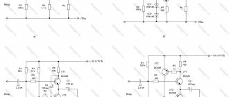
In practice, perhaps, another passive tone control circuit, with a simplified high-frequency control, has become more widespread (Fig. 6) [5-7].
Rice. 6. Diagram of a simplified passive bridge tone control
The calculation of such a regulator using tables and nomograms was proposed by L. Rivkin [5]. I translated L. Rivkin’s method into the language of the Microsoft Excel spreadsheet processor, which made it possible to do without nomograms, which are not entirely convenient to use and reduce the efficiency of calculations. A screenshot of an Excel spreadsheet with an example calculation is shown in Fig. 7. All agreements above apply here.
Rice.
7. Calculation of a simplified passive bridge tone control Test example No. 2.
Let's calculate a tone control with adjustment limits of ±17 dB, R2=R5=47 kOhm, fnr=30 Hz, fvr=18000 Hz. We get: R1=4.673 kOhm, R3=470 Ohm, R4=4.7 kOhm, C1=0.114 µF, C2=1.133 µF, C3=1916 pF, C4=0.019 µF. We choose from the standard E24 series: R1=4.7 kOhm, R3=470 Ohm, R4=4.7 kOhm, C1=0.1 µF, C2=1.0 µF, C3=2000 pF, C4=0.022 µF.
It should be recalled that in order to ensure the calculated depth of tone control, it is necessary that the load resistance of the tone control be much greater than its output resistance Rнрт≥(5…10)Rout≈(5…10)[R1R3/(R1+R3)+R4], and the internal resistance of the signal source is much less than the input resistance of the regulator: Rout≤(0.1…0.2)Rin≈(0.1…0.2)(R1+R3).
↑ Calculation of the tone control using E. Moskatov’s program
For the special case of adjustment depth ±20 dB, adjustment frequencies fnr=72 Hz, fvr=16000 Hz, Evgeniy Moskatov from the city of Taganrog developed the program “Timbreblock 4.0.0.0” (Fig. 8).
Rice. 8. View of the window of E. Moskatov’s program “Timbreblock 4.0.0.0” [8]
The calculation results for various resistance values of the variable resistors of the tone control are summarized in table. 1.