Add a link to a discussion of the article on the forum
RadioKot >Schemes >Audio >Amplifiers >
| Article tags: | Add a tag |
High quality power amplifier (100W)
Author: Published 09.22.2006
The amplifier offered to your precious attention is easy to assemble, terribly simple to set up (it actually doesn’t require it), does not contain particularly scarce components, and at the same time has very good characteristics and can easily match the so-called hi-fi, so dearly loved by the majority of citizens . The amplifier can operate on a load of 4 and 8 Ohms, can be used in a bridge connection to a load of 8 Ohms, and it will deliver 200 W to the load.
The main characteristics are as follows:
| Supply voltage, V | +/-35 |
| Current consumption in silent mode, mA | 100 |
| Input impedance, kOhm | 24 |
| Sensitivity (100 W, 8 Ohm), V | 1,2 |
| Output power (KG=0.04%), W | 80 |
| Reproducible frequency range, Hz | 10…30000 |
| Signal-to-noise ratio (unweighted), dB | -73 |
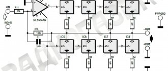
Amplifier circuit:
The amplifier is entirely based on discrete elements, without any op-amps or other tricks. When operating at a 4 Ohm load and a 35 V supply, the amplifier develops power up to 100 W. If there is a need to connect an 8 Ohm load, the power supply can be increased to +/-42V, in this case, we will get the same 100W. It is very strongly not recommended to increase the supply voltage above 42V, otherwise you may be left without output transistors. When operating in bridge mode, an 8-ohm load must be used, otherwise, again, we lose all hope for the survival of the output transistors. By the way, we must take into account that there is no short-circuit protection in the load, so you need to be careful. To use the amplifier in bridge mode, the MT
screw it to the output of another amplifier, to the input of which the signal is supplied. The remaining input is connected to the common wire. Resistor R11 is used to set the quiescent current of the output transistors. Capacitor C4 determines the correct gain limit and you should not reduce it - you will get self-excitation at high frequencies.
About the details.
All resistors are 0.25 W except for R18, R12, R13, R16, R17. The first three are 0.5 W, the last two are 5 W each. The HL1 LED is not for beauty, so there is no need to attach a super-bright diode to the circuit and display it on the front panel. The diode should be the most common, GREEN color - this is important, since LEDs of other colors have a different voltage drop. If suddenly someone was unlucky and could not get the output transistors MJL4281 and MJL4302, they can be replaced with MJL21193 and MJL21194, respectively. It is best to take a multi-turn variable resistor R11, although a regular one will do. There is nothing critical here - it’s just more convenient to set the quiescent current. Well, a sign so that everything is in one place:
| Designation on the diagram | Denomination | Note |
| R1, R4 | 2.2kOhm | |
| R2, R3, R5, R9 | 22kOhm | |
| R6, R7 | 560 | |
| R8, R10 | 1 kOhm | |
| R11 | 2kOhm | tuning |
| R12, R13 | 3.3kOhm | 0.5W |
| R14, R15 | 220 | |
| R16, R17 | 0,33 | 5W |
| R18 | 10 | 0.5W |
| C1 | 4.7 µFx25V | |
| C2 | 220 | |
| C3, C6 | 100 | |
| C4 | 100μFx25V | |
| C5 | 100μFx50V | |
| C7, C8, C9 | 100nF | |
| VT1, VT2, VT3, VT5 | BC546 | |
| VT4 | MJE15035 | Can be replaced with BD140 |
| VT6 | MJE15034 | |
| VT7 | MJE15035 | |
| VT8 | MJL4302 | |
| VT9 | MJL4281 | |
| HL1 | AL307 | GREEN |
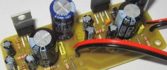
The actual setting comes down to setting the quiescent current of the output transistors with resistor R11 to approximately 75-90 mA. Of course, we put the output transistors on radiators. Area - 300-400 sq. see for each. VT6 and VT7 can also make life easier by screwing them onto radiators of 50-70 sq. cm.
You can steal the printed circuit board here. It seems like I haven't forgotten anything. But if anything happens, the Forum is open 24 hours a day.
| What do you think of this article? | Did this device work for you? | |
| 54 | 3 | 4 |
| 5 | 1 |
DIY: 100W Tube Amplifier
As it turned out, it’s not difficult to do.
For quite some time now I have been thinking about building a tube amplifier. Despite the fact that I have practically no knowledge in the field of lamp circuitry, I didn’t want to buy a ready-made one. And not being a fanatical lover of warm tube sound, the assembly process itself was interesting to me. The hardest part was finding the output transformers. I bought myself ready-made ones from the TU-100M amplifier. The scheme was almost completely repeated as on the TU-100M with minor changes. The whole theory is very well described here and here. I started assembling the case with a frame made from an aluminum profile. I went a little overboard with the safety margin.
The upper part of the body was made from 3mm. steel Holes for transformers and lamps were laser cut.
The bottom is cut from 2mm. steel with ventilation holes.
The front panel was made from this piece of aluminum.
After sanding:
Cut and ready.
Electrical diagram. The final amplifier is assembled using a push-pull circuit using two G-807 lamps (widespread).
The preamplifier contains two amplification stages assembled on a 6N9S double triode (a foreign analogue of 6SL7, lamps from the Moscow Electric Tube Plant produced in the 50s are especially valued).
Advantages of 6N9S: 1) The lamp was originally designed for audio use. 2) Two triodes in a cylinder. 3)High linearity. 4) Wide distribution, low price. Disadvantages: 1) High internal resistance.
The pre-terminal amplifier (an intermediate link between single-ended and push-pull amplifiers) is assembled using a phase-inverted circuit on a 6N9S double triode; its main purpose is to form two mutually antiphase, equal in amplitude signals from the input signal. In the TU-100M circuit, the lamp amplifies the input signal and the voltage amplified by it is supplied to the lamp grid of the first arm of the push-pull amplifier. Part of the output voltage of the first lamp of the phase-inverted amplifier is supplied to the input of the second lamp of this amplifier. The voltage amplified by the second lamp of the phase-inverted amplifier is supplied to the grid of the lamp of the second arm of the push-pull amplifier. That. For the first arm of a push-pull amplifier, the signal passes through one tube, and for the second through two.
It is necessary that the voltage supplied to the input of the first arm be equal to the voltage at the input of the second arm. I tried a slightly different circuit, with a modified phase inversion stage. Drew it in paint)
Advantages: 1) Reduced requirements for filtering the supply voltage. 2) Extremely low noise level. 3) Equal output voltages of the shoulders.
Sockets for 6N9S lamps.
The amplifier housing contains a DAC with the ability to connect to a computer via USB.
The first, adjustment option.
The transformer screens were cut from 2mm steel.
After fitting with a file.
After sanding.
Painting the body with varnish.
Ready block.
some more photos
The orange glow of the filaments creates a pleasant listening atmosphere, which is inherent in tube amplifiers.
Price. Transformers, radio tubes G807, sockets for lamps - 5000 rubles. (avito.ru) Radio tubes 6N9S (4 pcs.) – 560 rub. (Radio store) Aluminum profile for the frame - 1500 rubles. I took with reserve (Leroy Merlin) a 3mm steel sheet with laser-cut holes for the transformer - 700 rubles. Bottom with cut out ventilation holes - 700 rubles. Screens for transformers – 3300 rub. Capacitors and various small items - 3000 rubles. Consumables -1000 rub. Total: 15760 rub. In total, I spent about 3 of my scholarships.
In conclusion, I want to say that high voltages are too insidious. Lamp designs use life-threatening voltages. When working with circuits, be extremely careful and careful! Even a device disconnected from the electrical network poses a danger - capacitors can store a charge for a long time, I was convinced of this several times). I checked the box every time the capacitors discharged on me. Invigorates!
Information from the datasheet about TDA7498
The new ULF chip TDA7498 class – D, 2 x 100 W, is designed specifically for audio amplifiers, DVD/CD players, home theaters and active speakers. The amplifier operates in class D and has exceptionally high efficiency with a low level of heat dissipation, which helps eliminate large-sized cooling radiators and, as a result, reduce the height and cost of the entire device.
TDA7498 structural diagram
All class D amplifiers in this series are manufactured using BCD6S , which allows you to combine digital, analog and high-voltage circuits on one chip, which simplifies the development process, increases the reliability of the device, and reduces the size and cost of the product.
Assembly and testing
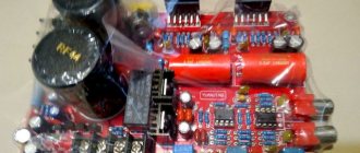
There were no problems when starting the amplifier; the advantage of such modules is the complete absence of any adjustments or adjustments.
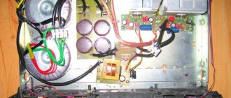
The case is taken from a burnt-out satellite tuner (we've been thinking about where to use it for a long time), the front panel is a 3 mm metal plate. Among the useful additions, you can install an input selector, change the transformer power supply to a powerful switching one, and install an automatic cooling cooler.
