One of the popular manufacturers of car radios is JVC. Car radios of this brand have long been loved by motorists. The advantages of radio tape recorders from this manufacturer are:
- the buttons and symbols on the screen are standard so that the user does not get confused;
- convenient control;
- The pinout of the JVC radio can be done by the user independently.
Before connecting the radio, you need to check the conformity of the box. There are 2 standards:
- European;
- American (also used in Japan and South Korea).
In the first case, a single-block version is used or it is also called 1DIN, in the second - a double-block or 2DIN.
Tips on how to connect a jvc radio
Among all the abundance of car radios on the car market, choosing a truly high-quality device is becoming increasingly difficult, because radios from unknown manufacturers with the same dubious quality are springing up like “mushrooms after rain”. But there are a number of manufacturers who have proven themselves on the market only on the positive side. Among them are JVC, Pioneer, Kenwood, Alpine and others. And in this article I would like to discuss the process of connecting JVC radios, because this company is the most popular today.
Pinout of a standard Euro connector
The Euro connector is a standard plug for many modern devices. An ISO plug is installed on the machine, thanks to which it becomes possible to connect any model of radio with the appropriate connector.
Standards 1DIN and 2DIN
The difference between the standards lies in the size of the devices: a 2-din device is 2 times higher than a 1-din device.
The most common are 1-DIN radios, because Installation of higher devices due to the lack of a seat of appropriate size on the front panel of the car is not possible in every car.
There are 2 types of radio tape recorders:
- With proprietary connector. You need to choose a product whose pinout matches the desired car.
- With universal connector. The device connects directly to the ISO socket provided in the car.
Pinout is carried out according to ISO 10487 standard.
Upper power connector A
The connector serves as a connector between sources and consumers of electricity from the on-board network.
Plugs 1, 2, 3, 6 are rarely used in radio circuits of the lower and middle price segments. The elements are used when connecting additional options in higher quality player models. Wire colors may vary.
You should understand the purpose of the contacts:
- ANT. Used with a retractable antenna.
- Remote. Designed for connecting external amplifiers. Thanks to it, you can increase the number of mounted speakers, which is necessary in the interiors of large cars.
- Illumination. Adjusts the brightness of the player screen (the higher the driving speed, the less intense the backlight, so as not to distract the driver).
- Mute. Adjusts the sound of the device.
- A4. Turns the audio system on and off.
This connection scheme allows you to protect the battery from discharge, because turning on the system is possible only when you turn the ignition key, while the acoustic cascades consume electricity even when turned off.
The pinout of the ISO connector of the radio (European) looks like this:
- Connector A5 (blue) is for the antenna. If the permissible current value (300 µA) is exceeded, both the amplifier stages and the entire head unit may break.
- Wire A7 (red) is intended to power the head unit. When it is disabled, the settings are returned to factory settings. Voltage - 12 V.
- Cable A8 (black). Responsible for connecting the speaker system to the car.
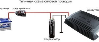
To protect the audio system, the wires must be equipped with a fusible link. If interruptions occur in the operation of the player, you should place a capacitor between connectors A7 and A8, which will act as a filter, smoothing out fluctuations in the electrical circuit.
Bottom speaker connector B
The speakers are connected through it as follows:
- Rear right + (purple).
- Rear right - (black and purple).
- Front right + (gray).
- Front left - (black and gray).
- Front left + (white).
- Front left - (black and white).
- Rear left + (green).
- Rear left - (black and green).
Most devices are designed for 4 channels; 8 wires are used for this (2 pieces per speaker).
The sound quality of the system depends on the “flattening”. If you mix up the connectors, the device will not fail, but the radio will not work correctly.
Audio system elements should be connected with cables with a cross-section of 1.5 mm or more. Thicker wires are used on power lines.
What types of tape recorders are there?
Among the variety of car radios, there are only two types of devices, which differ in shape.
In the CIS countries and Europe, single-block or 1 DIN are more common, and for America, Japan and Korea, double-block or 2 DIN.
You should also note that to install radios of various types you will have to purchase the appropriate boxes.
Important! Carefully examine the panel of your car, because it may turn out that only a certain type of device can fit into it.
Connection adapter
According to European standards, all wires connected to the car radio must comply with the same ISO marking. But at the same time, many manufacturers produce various plugs and JVC radios are no exception. Therefore, when buying a car radio, you need to make sure that there is an ISO adapter, and if it is not there, you will definitely have to get one.
Modern car models are equipped with adapters for the European standard, but most do not have them, so the radio will have to be connected directly to the wiring.
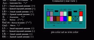
But for these purposes you need to know the color scheme for connecting the JVC radio:
- Red wire – connects to the positive terminal (+12V);
- The yellow wire is also connected to the positive wire going through the ignition switch (+12V);
- Blue wire – a terminal of this color is connected to control the antenna (+12V);
- Black color - should go to the body of the car, that is, it is a mass;
- White wire – goes to the front left speaker;
- Gray wire – designed to connect the right front speaker;
- Green color – goes to the rear left speaker;
- Purple wire - attaches to the rear right speaker.
The wires going to the negative terminals of the speakers are marked with an additional strip of black (sometimes gray or white).
If you connect two yellow and red wires together, you can ensure that the car radio will work even when the ignition is turned off.
Important! The red positive wire must have a fuse. And when connecting the yellow and red wires in a bunch, they should also be fed through a fuse.
The process of connecting the radio
If your car has a built-in ISO terminal, then there will be no problems connecting the JVC radio; the main thing is to check the markings of the wires and adhere to the diagram included in the package with the radio.
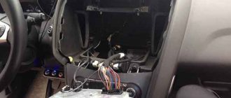
Otherwise, the connection will have to cut directly into the wiring itself or throw the wire directly onto the battery terminal.
Important! When connecting the radio, all sources of electricity should be turned off, and if this is not possible, each wire must be thoroughly stripped, soldered and insulated (an example of a connection can be seen in the photo below). Without touching the positive terminals to ground or wires going to the speakers.
In addition, connection points such as the cigarette lighter and ignition switch should be avoided.
For safe operation of the JVC radio, its connection must be made with a stranded copper wire with a cross-section of at least 4 mm and a 10-20A fuse installed on it. If the connection is made from the battery terminal, the fuse must be located at a distance of more than 40 cm from it.
Interesting! Mounting the JVC radio directly to the battery terminal ensures better sound of the tracks, thanks to less drawdown and interference from operating equipment.
It is advisable to use the negative wire as short as possible to reduce the length; it can be attached to the car body.
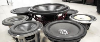
Connecting speakers and selecting speaker wires
To connect speakers to the JVC radio, use only speaker wires of the appropriate cross-section. So, for speakers with a power of up to 100 W, you can use a wire with a cross-section of up to 4 mm made of oxygen-free copper. These wires are very soft and are most often protected with silicone insulation, which is very practical; it will not “stiffen” in the cold. There are also arrows on the wires indicating the direction of laying the wires from the radio.
Most speakers have markings for connecting the positive and negative terminals, but sometimes there are none; in this case, the wide terminal indicates positive, and the narrow terminal indicates negative.
Summarize
Connecting a JVC radio is not difficult, the main thing is to carry out all operations carefully and according to the diagram provided with the device. You should also remember that installation will require some tools, because laying the wires will require partial or complete disassembly of the interior.
If you still have questions about installing the JVC radio, you can watch a detailed installation video.
The main condition for a quality installation is self-confidence, otherwise it is better to leave the installation to professionals.
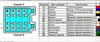
Car radios without a plug: determining the pinout
The following option can be considered a more complex problem. When the connector to the board is simply missing, along with the documentation. What to do in this case? There is one working way to solve this problem. The chip for connecting the car radio may be lost, the location of the pins is inaccessible, but the correct circuit can be determined.
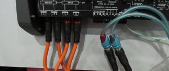
Car radio connectors
This can be done in any radio, both elite ones - JVC, Pioneer, Sony, and branded ones, for example, Toyota. It is easier to determine the location of pins on a radio of a well-known brand than on an unknown one. The same situation is with domestic VAZs. The pinout can be found freely on the Internet.
The problem is with car radios with an exotic manufacturer and the same exotic connector. Moreover, in some cases, the connector may differ not only between models, but also between batches. For these purposes, you will need a multimeter, which you will need to connect and “ring” the contacts.
Determining the power wires
First you need to find the power wires: “yellow” and “black”. The yellow wire is found as follows. In most cases, the “yellow” and “black” power pins are larger in diameter and stand out well from the others. But sometimes this may not be the case.
Power cables
The “negative” one is usually looped onto the body of the car radio, respectively, if one contact of the multimeter is connected to the body, the other to the terminal. “Minus” will ring the contact. The other one will be a “plus”.
Finding the control red wire
To find the control “red” wire, you will need to connect a 500-800 Ohm resistor. Also use a 12 V power supply, connect the negative wire to the case, the positive wire to the plus defined in the paragraph above. Turn on the power supply. Then connect one resistor output to positive, the other to all remaining contacts, but on the board due to the limited length of the resistor. The car radio will turn on at the desired contact.
Conclusions to the speakers
Next you need to find the leads going to the speakers. Usually they are displayed on contacts:
- front left, front right;
- rear left, rear right.
We are talking about paired contacts at the beginning or end of the connector. On the plan you need to find the amplifier chip. Speaker leads can be determined by the width of the tracks; they are usually one of the widest. Using a multimeter, you can determine which speaker is right and which is left. This is well commented on in the video, which shows all the mentioned elements of the microcircuit and clearly explains the nature of the connector and how to restore it.
Multimeter
Peculiarities
So, let's summarize. First of all, there is always the opportunity to use a Euro connector and forget about the difficulties of switching from a unique circuit. If it is missing, the location of the contacts is determined empirically by ringing the contacts. First there is power, then the control wire, then the speakers. After identifying all the contacts, the chip for connecting the radio is made independently.
Branded car radios such as Toyota or JVC have all types of plugs publicly available. An ISO adapter can also be purchased for connection to them.
Connectors for car radios
Conclusion
Using the described method, you can safely connect a radio without a chip; this makes it possible to revive almost any device without a plug. This feature helps you save on the purchase of more expensive models that are not sold complete. The restoration process will not cause difficulties even for people without experience in the field of electrical engineering and electronics. You can connect everything yourself, this is a huge advantage of the proposed method.
JVC radio pinout diagram and instructions on how to connect (set up) Jivisi
One of the popular manufacturers of car radios is JVC. Car radios of this brand have long been loved by motorists. The advantages of radio tape recorders from this manufacturer are:
- the buttons and symbols on the screen are standard so that the user does not get confused;
- convenient control;
- The pinout of the JVC radio can be done by the user independently.
Before connecting the radio, you need to check the conformity of the box. There are 2 standards:
- European;
- American (also used in Japan and South Korea).
In the first case, a single-block version is used or it is also called 1DIN, in the second - a double-block or 2DIN.
List of supported compatible mobile phones
・ = can be used. — = function not available.
Notes
*1 Can be used, but operation is not stable.
*2 Pairing is only possible with PIN (Personal Identification Number) “0000”.
*3 There may be situations where the mobile phone will restart during a call.
* It is not possible to remove the phone book from the SIM card.
*5 Data other than the phone book (dialed, received and missed calls) cannot be retrieved correctly.
*6 When receiving a call, you cannot retrieve the incoming call number.
*7 Sometimes the correct name/phone number may not be displayed when there is an incoming call.
How to connect a radio
You can connect the radio in 2 ways, depending on whether the car is new or not. Modern new cars have an ICO adapter. It is universal, and if it is available, almost any driver can handle the connection. All you need to do to connect the radio is follow the instructions.
Not all cars have such a universal adapter. In modifications of the old type, the connection of the radio was performed by connecting directly. To do this, it was necessary to know the connection sequence.
Before connecting the radio, you need to disconnect the power sources. When this cannot be done, the wires must be thoroughly stripped and soldered. They are then isolated. It is better not to touch the ground and those wires that are connected to the speakers, the positive terminals.
Use copper wire with several cores, with a diameter of 4 mm and install a fuse. With terminals, the distance from them to the fuse exceeds 40 cm.
Pinout diagram
For correct pinout, the following connection diagram for the JVC car radio is used:
- the wire marked in red is connected to 12 V plus;
- the wire marked in blue is connected to the antenna control;
- the yellow wire is connected through the 3Z to the plus;
- the wire marked white goes to the left speaker;
- the black wire goes to the body (ground);
- the green wire is connected to the left rear speaker;
- the gray wire goes to the front right speaker;
- The purple wire goes to the right rear speaker.
In addition to this connection diagram, it is important that the negative wires have stripes: black, gray or white. The fuse is important on the red wire, as is the case if you connect the red and yellow wires.
DIY car radio connection diagram
Today, radios are powered by a yellow power “plus” connected to the positive terminal of the battery. There is another way: the radio can be connected to the corresponding wire in the car. This wire must have a permanent connection to the battery and the required cross-section. In any case, we advise you not to forget that you should have instructions at hand, which will greatly facilitate connecting the car radio.
Next you need to connect the black ground wire - it needs to be secured to the car body with a screw as in the connection diagram.
The other “positive” wire, which is usually represented in red, you must connect to the ignition switch. With this connection, you will ensure that only when you turn on the ignition directly, you can turn on the radio itself.
If you are willing to take a risk, you can connect the red wire together with the yellow one, which will allow you to turn on the radio regardless of the position of the ignition switch. However, the risk is that with such a connection, the car radio will be in standby mode all the time, and this can put a strain on the car’s battery, for example, while parking.
So, with the power cables done, you can now connect the speakers. Do not forget about the polarity - if there is an error, the radio may be damaged.
The next step is to connect the antenna. If you have a passive antenna in your hands, then connecting it will not take time - just connect the plug to the corresponding socket. If you want to connect an active antenna, then it will be very important to connect an additional power wire from the antenna to the contact in the radio. And, as in the first case, you need to connect the plug.
If you did everything correctly, then your DIY car radio should work.
User guide
The operating instructions for the JVC car radio contain warnings:
- You should not use options that distract from safe driving on the road. The main thing in driving is to follow traffic rules.
- Before starting playback, it is better to lower the volume to prevent damage to the speakers due to sudden changes in sound.
- The volume of the radio should not drown out the sounds outside the window so that the driver can hear what is happening around.
- It is not recommended to use devices that distract from driving or in any way affect traffic safety. The car radio should not distract the driver's attention from the movement.
- If condensation forms on the disk, a read error may occur. In this case, the disc must be removed and dried.
- Saved data must be copied to avoid loss.
- It is not recommended to insert metal objects into the device to prevent short circuits.
- It is not recommended to leave the radio remote control on the dashboard.
- It is recommended to replace lithium batteries only with original ones, as they can explode.
- Batteries should be kept out of the reach of children and not exposed to heat from the sun or fire.
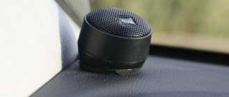
Main mechanisms and controls on the front panel of the JVC radio:
- There may be a button to release the radio panel in the lower left or other corner.
- The round knob is a volume control. On some models, the volume is adjusted using buttons marked “+” and “-”.
- Display. Shows the status of the radio, the names of tracks, albums, and other information.
The power is turned off with the button with the power or source icon. To do this, you need to press and hold it. The volume is adjusted using the “vol +” and “vol -” buttons. Otherwise, operation is the same as with any audio equipment. Button with a triangle - playback; with two triangles forward and backward - “next track” or “next album”.
You can switch to the previous track and album.
The button with a square stops playback.
Each JVC radio model has its own manual. And although the general principles of using the radio are the same, each model has features and additional capabilities, which are best read in the instructions for this model.
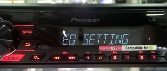
How to set up a radio
When you turn it on for the first time, you need to configure the JVC radio. As soon as the device is turned on, you need to reset the demonstration. When the display displays the information “Cancel Demo” - “Press” - “Volume Knob”, you need to do the following:
- press the volume knob;
- then press it again, the “Demo Off” entry should appear.
In addition, you need to configure the radio by setting the basic parameters. Setting up the car radio to basic parameters is done as follows:
- press and hold the button with squares, above which a gear is drawn;
- the desired element is selected by turning the volume control (or arrows in the case of a push-button option);
- to select the active element, you need to press the volume control knob;
- then to exit, press the button with the squares and gear above it again.
The car radio can be configured to suit any parameters. Just select the desired value. The list of basic parameters will be provided by the instructions intended for the desired model. When the installation of basic parameters is completed, you can begin operation. In the same way, we configure not only the basic parameters, but also any others as necessary.
Setting the time
Setting up the car radio involves setting the date and time. To complete these tasks you need:
- Press and hold the button with squares and gear.
- Select Clock by turning the volume control, then pressing when this menu item is active.
- By turning the volume knob we find the Clock Adjust setting item and press the knob to enter the menu item.
- By turning the knob, we scroll through the hours and minutes to the desired values and press the knob when the desired value is selected.
- Now you need to select the format - turn the volume knob to the Clock Format item and press it.
- Turn to select 12 or 24 hour format and press the volume knob.
- To set the date, turn the knob to the Date Set menu item.
- We select date values by turning the volume control, then pressing when the desired values are reached.
- Exit by pressing the button with a square and a gear.
The JVC radio time and date can be set when needed and after basic settings. For example, when traveling by car to other regions of the country.
Important note for Bluetooth operations
When using Bluetooth features, you should be aware of a number of circumstances from the list below, including potential issues. Please read it carefully.
General remarks
・ Since Bluetooth is a wireless connection, there may be times when normal communication is not possible due to signal quality.
・ The mobile phone models listed here have been tested and found compatible with JVC, status as of September 2010. If any modification has been made to the mobile phone after our test, the available features may differ from those listed here.
・The compatibility status shown above corresponds to the device instance we used for the test. This does not guarantee that all instances of the same mobile phone model will produce the same results.
・ Some functions may require operations from a mobile phone. See your mobile phone's manual for more information.
・Model names or model numbers are trademarks or registered trademarks of their respective owners.
・ PC connection is not supported.
・The number of characters available for each information display varies depending on the JVC head unit display. All symbols may not always be displayed.
・ Some functions may not operate properly depending on the settings and status of the connected mobile phone. For example, on certain mobile phones, you can only make a call using the JVC head unit while the mobile phone display is showing the standby window.
・ All Bluetooth related functions are dependent on the mobile phones connected to the JVC head unit.
Pairing
・ The JVC head unit may not be detected depending on the signal conditions or mobile phone settings.
・ If the display does not show “Connect”, “Pairing OK”, etc. after the pairing operation is completed, the pairing has failed. In this case, try pairing again by deleting Pairing on both the JVC device and the connecting device.
・ On some mobile phones, the PIN (Personal Identification Number) is fixed. (for example "0000")
・Pairing and connecting operation varies depending on the mobile phone. Check the operation of this operation on your mobile phone in advance.
Connection
・ There may be cases where automatic connection is not established properly even if “Auto Connect” is set to “ON”. In this case, try again after confirming the mobile phone settings or turning off the JVC device and your mobile phone.
・ The connection status displayed on the JVC head unit is not necessarily the same as the connection status displayed on the connected mobile phone.
Recruitment, reception (HFP)
・Noise or loud echo may be generated during a voice call.
・ On some mobile phones, the HFP (head unit to mobile phone) Switched Conversation mode may not work properly, or noise may be generated when switching.
・ The JVC head unit and the mobile phone may not always coordinate properly (for example, the mobile phone cannot interrupt the call even if the JVC head unit finishes displaying the call function, etc.)
・ On some mobile phones, the caller's number and name may not be displayed correctly when receiving a call, making a call, or talking to a caller in idle mode. (for example, depending on your mobile phone model, the plus sign (+) may not be displayed)
・Call waiting mode is not supported.
・ Some mobile phones may not be able to reject an incoming call because they do not support this function.
How to find a fault
A car radio, like other equipment, can fail over time and have various malfunctions. To understand how to find a fault in JVC RC and other radios, you need to know that there may be several main reasons:
- Contamination and mechanical damage to the radio. Over time, dust and dirt accumulate in the mechanisms, which can lead to problems.
- Voltage fluctuations can cause malfunctions in electrical circuits.
Only a professional can perform high-quality car radio repairs. Mechanical faults can be eliminated yourself by cleaning the radio. But if you have never had such skills, then it is better to seek help from a professional.
If it doesn't turn on
When the radio does not turn on, the reason may be due to lack of power. It is worth checking contact CN701, which should have a voltage of 14 V.
If there is no voltage, replace the transistors or zener diode.
Another reason when turning on does not occur may be the lack of a power signal.
If the buttons don't work
Buttons can break due to mechanical damage or simply become clogged with dirt or dust. In the second case, cleaning the radio will help. If the buttons break, you may have to look for new buttons on car enthusiast forums, in services, or when buying old equipment second-hand. It will be easier to replace the panel, but it all depends on the situation and model of the radio.
Many sellers have long given up replacing parts and, if a part breaks down, they offer to replace the entire mechanism or purchase a new device. Specialized repair shops can help out by buying up old equipment for spare parts and using them to carry out repairs. The main thing is that the cost of such repairs should not be close to the cost of a new device.
What are aux inputs and outputs?
In Russia and some CIS countries they are called linear outputs. They are small connectors that can be supplied with voltage from 0.4 - 1.9 volts. In Western countries, this connector is labeled aux out or cd out.
If your device has connectors such as aux input or aux output, then in most cases such a player is equipped with an audio signal amplifier and is capable of working with other external devices. By connecting a smartphone or MP3 player through this connector, you can listen to audio files through the car speakers.
But the saddest thing is that not all old-style radios have such outputs. And if you want to listen to your favorite music from your own media, the owner will have to buy a radio with an aux input installed, or make aux on the standard radio, paying a lot of money in the first and second options.
After some thought, the thought often arises that there may be a possibility of making such a connector yourself. Let's consider the options.
How to connect a JVC radio
Most of these radios are equipped with a proprietary connector. To connect JVC to the on-board network, you need to purchase a special adapter. You can also connect a radio if it is missing. This can be done in 2 ways:
- By connecting the wires to the pins on the connector.
- By soldering the wires to the radio board in accordance with the designations.
In both cases, you must be guided by the device connection diagram. The pinout of the JVC car radio wires is as follows:
- The first and second are the output of the front and rear right speakers, respectively.
- The third and fourth are the left rear and front speaker outputs, respectively.
- The fifth one connects to the remote control (RC) device.
- The sixth one connects to an active antenna or car audio amplifier.
- The seventh is connected to the power source.
- The eighth is connected to the negative pole (car body).
- The ninth and tenth are the mass of the right front and rear speakers, respectively.
- The eleventh and twelfth are the mass of the left front and rear speakers, respectively.
- The thirteenth is responsible for muting the sound while talking on the phone when there is a short to ground.
- The fourteenth and fifteenth are not used.
- The sixteenth wire is the main power supply for the radio.
If there are holes in the pins of the block on the back wall of the radio, then for connection you will need needles that will be inserted there. You also need to prepare the wires. Their colors are chosen in accordance with generally accepted markings to facilitate connection of the device.
One end of the wire is securely screwed to the needle. To isolate such connectors from each other, tubes are put on them. After installing all the needles in place, the resulting structure is fastened and fixed with adhesive tape. First, the needles with tubes are wrapped in several layers, and then attached on several sides by gluing to the back wall of the radio.
If you cannot connect the radio using needles, then you should solder the wires to the contacts on the printed circuit board. To do this, remove the top cover of the device and carefully remove the board from the case. Then the wires are soldered to the connector contacts according to the car radio connection diagram. To route the cables out, carefully drill a hole in the back wall of the device closer to the soldering point.
All about the connector for connecting radios of various models
You can connect the radio yourself, the main thing is to figure out how to do it correctly. Despite the different types of radios and car brands, the connection process remains approximately the same, but some subtleties of the matter should be taken into account.
What types of connectors are there?
Car radios according to installation method are:
- Stationary. This radio is installed at the factory during vehicle assembly. They are distinguished by their original design and various sizes;
- Built-in. As standard, the kit includes a removable panel or curtain.
You need to connect the radio only according to the instructions. An incorrect connection can lead to damage not only to the radio itself, but also to the car.
If the radio is connected incorrectly, you may encounter the following consequences:
- The radio quickly drains the battery;
- The sound of the music being played is distorted, interference appears, or uncontrolled shutdown occurs;
- All settings are lost.
The connection diagram can be found on the top cover of the car radio.
How to setup
After connecting, you should configure the JVC radio. First you need to disable the demo mode by pressing the volume encoder twice. To set the clock on your JVC radio, go to the menu by pressing and holding the corresponding button, and then set the time display to 24-hour format and the appropriate time zone. After this, the hours and minutes are set by turning the volume control.
To confirm the changes you make, you need to click on it. To exit the menu, press the car radio settings button. The sound parameters can be adjusted by pressing the corresponding button.
In this mode, you can customize the sound by adjusting the tone in 3 bands or using the equalizer.
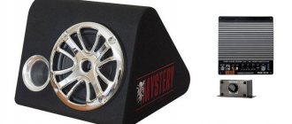
The JVC car radio provides the ability to connect a subwoofer to the rear speaker outputs. In this case, the output type and low-pass filter are configured. Additional configurable parameters include output power limitation, backlight and display button color, language and text scrolling method, etc.
HONEY & TAR
The JVC KD-X375BT has considerable potential and will not be exhausted soon. The sound is pleasing; the capabilities of the built-in equalizer, crossover and signal processing functions are more than sufficient even for sophisticated listeners. And the price is fabulous. The downside is traditional - inconsistent Russification of the menu, the result was not brought to a common denominator - but we are here to read the menu. The final opinion can be expressed in two words: “must take it.”
User's Manual
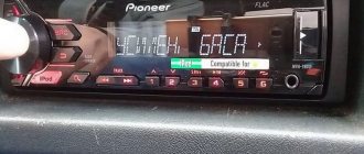
To manually tune the radio, hold down one of the navigation buttons until the M symbol appears, then press it several times to select the desired frequency. To automatically search, you need to press and release the same button in accordance with the operating instructions. Mute or pause playback by pressing the volume control.
This radio can be connected to an Android smartphone that supports Android Open Accessory tools. In this case, you can go to the previous or next track using the buttons on the radio. The rest of the operations are performed from the smartphone. When listening to music from a disc or flash drive, you can also switch between folders and control repeat and random playback in accordance with the manual.
What can you encounter if your car radio is not connected correctly?
This is not to say that to properly install a radio, you don’t need to have any skills at all. It is advisable to have at least initial experience in connecting electrical devices, but this is not a prerequisite; following the instructions, a person can complete the installation without any experience. To understand whether everything was done correctly, it is worth monitoring the operation of the radio. A sign of an error will be the presence of the following factors:
- The radio turns off when the volume is increased.
- When you turn off the ignition, the radio settings are lost.
- The radio drains the battery when turned off.
- The audio signal is noticeably distorted, especially when listening at high volumes.
In very rare situations, it is not the person who connected it who is to blame, but the seller who sold the low-quality product. Of course, this option cannot be ruled out, but you will still need to double-check the connection diagram.
Malfunctions and their elimination
As with other radios, JVC receivers may experience problems. They may be caused by internal faults, the use of low-quality speakers and other accessories, etc.
How to find a fault
You can find breakdowns in JVC radios by their characteristic features. If some functions do not work as expected, this may be due to a device settings failure. Unnatural sound is caused by incorrect equalizer settings. Weak, missing, or distorted sound may be caused by damaged or shorted speaker wiring.
Buttons don't work
If the buttons on the panel do not work on the JVC car radio, you should check whether it is installed correctly. Then you need to remove it and inspect the contacts on the back side. If they are dirty, the display backlight may not light up. After cleaning the contacts, the control panel is carefully installed in its place.
Another reason for buttons not working is sticking or wear due to prolonged use. A remote control must be used. Some buttons can be replaced by disassembling the JVC car radio panel and soldering new ones.
Doesn't turn on
If the car radio does not turn on, you need to check whether the fuse in the power circuit has blown. Another reason for complete inoperability is an incorrect or unreliable connection to the device’s power supply circuit. The fuse is located on the rear panel of the radio. To eliminate this problem, you should replace it with a similar type with a rating of at least 10 A.
When checking the connections of the power circuits, make sure that the wires are not damaged. The negative cable should be connected to the car body closer to the radio, if there is a pin there. You also need to check whether the positive wires of the radio are connected correctly. If one of them is turned on through the ignition switch or is not connected to the on-board network, the radio will not work. To resolve this problem, connect the red and yellow wires together and connect them to the battery.
JVC KD-R90BT Settings
USB adapter for radio. or how to connect to a standard head unit. it turns out everything is not so hopeless
Setting up a JVC car radio
It is worth noting that the JVC KD-R90BT radio has a fairly simplified version of the settings, which is a big plus for the average user. Many car owners often have difficulty setting up filters. The main feature of this device is the “Easy” function. That is, you no longer need to adjust the frequencies of the speakers, but simply select their size. The program will automatically select the necessary parameters. Among the more professional settings is “DSP”. EQ is a five-band equalizer with optimal settings for a particular genre of music. The DSP system is a detailed adjustment of the transmission of a sound signal to a particular speaker. That is, like a professional studio, you can create a uniform sound field for listeners inside the car.
Note. An unusual innovation is the choice of car body and sound focus point when first started. That is, the radio will automatically adjust parameters aimed at uniform delivery of the sound wave. Of course, more experienced users will always have the opportunity to adjust the radio “to suit themselves.”
Thus, we have the following types of settings:
- “Easy” mode (automatic sound settings).
- “EQ” mode (5-band equalizer).
- “DSP” mode (determining sound delay).
- Digital Track Expander mode (which takes compressed tracks to a new level of sound).
You can do the setup yourself. Before starting this process, you need to familiarize yourself with the various photos of similar topics that are available on the Internet. The video will also be very helpful. Usually the instructions are sold as a set and contain a lot of useful information. The price of this service work can be very high.
JVC car radios
JVC car radios and connection diagram
As a rule, today there are no problems with purchasing a car radio. Everyone will be able to choose the model they like, in accordance with their individual needs. JVC is especially good in this regard, as it annually updates its product line, releasing new and attractively priced devices.
Note. Thus, JVC/Kenwood recently presented 4 new diskless receivers designed for active mobile phone users. Elegant design, full integration with smartphones, signature sound, and ample capabilities are not the only advantages of these devices.
Installation of new receivers is carried out in the standard place designated by the automaker, 1 din. There are also 2-din devices that are larger in size. In both cases, you cannot do without the correct pinout of the connectors.
Radio circuits. — JVC car audio circuits
JVC car radio circuits
This section contains diagrams of JVC car radios (and other car audio equipment)
All circuits in the category car audio
YOU can download any of these diagrams (the diagrams are in the attachments at the bottom of the page). Moreover, you can download all this completely free of charge, without registration, without SMS, without file sharing and other hidden difficulties.
To view files you will need WinRAR, 7z archivers and programs for viewing files in pdf format; you can download all this on our website in the software section.
All files have been scanned by antivirus!
Maybe
Installation and connection features
jvc car radio connection diagram
JVC cares about its consumers. The car radio models they produce are made so that the user himself can install them. For example, the manufacturer took care to equip its devices with a special pin for fixing the back of the device and a decorative gasket. Thus, it is much easier to remove the car radio using standard hooks.
Note. Of course, car radio models with conventional screw fixation are also produced. They are even more reliable in some ways, but do not forget that the screws must be screwed in to a depth of no more than 6 mm.
But, again, the main thing when connecting devices in a car is the connectors. Most cars produced in recent years are equipped with a special connector (see What types of connectors are there). It is called ISO - it is a universal connector, the connection with which is reduced to just connecting the plug. It’s a matter of just a few minutes, which even a schoolchild can handle, but only if the instructions are strictly followed.
Note. Unfortunately, such a connector appeared relatively recently. But early modifications of BMW, Nissan, Honda and other cars do not have such a connector. In this case, the connection may cause some problems if you do not know the features of the process and the pinout of JVC car radios.
JVC car radio connector pinout
Standard pinout of JVC device connectors
As a rule, most JVC car radio models must be connected according to the following scheme:
- Pull the gearbox from the battery. This is 12V power supply;
- SP responsible for the power antenna;
- Pass the gastrointestinal tract through the zz;
- The easiest way to transfer the emergency situation responsible for the mass is to transfer it to the body in the most convenient place for this;
- FP is a plus on the right rear speaker;
- ZP is a plus on the left rear speaker;
- SRP is a minus on the right rear speaker;
- The power supply is a minus for the left rear speaker.
*KP – red; SP – blue; ZhP – yellow; PE – black; FP – violet; ZP – green; SrP – gray; BP – white; ZZ – ignition switch.
Note. You should know that on JVC car radios the negative wires are painted not only in the main color, but also have a black stripe. As for the ZhP and KP, they are often combined together. This makes it possible to listen to music without the ignition key. In addition, this technique significantly improves sound quality.
A similar scenario can be achieved if the wires are not connected to each other, but only by moving the fuse. In particular, you can do the following:
- Move the fuse located at the end of the JVC devices to the adjacent socket;
- Connect only the gearbox to the battery;
- It's easy to insulate the housing.
Advice. To achieve normal playback and clear sound without distortion, you need to pay considerable attention to the wires and their quality. Thicker cables are ideal for power, while stronger connectors are ideal for connecting to speakers. The wiring that comes with the devices is usually not of the best quality.
In the process of carrying out operations with your own hands, it will not be superfluous to watch videos and photos. Step-by-step instructions will also be helpful. JVC car radios are very popular today and their prices are affordable.
When installing a car radio, it is useful to know
During the process of installing and connecting a radio in a car, non-standard situations often arise that cannot be foreseen in any instructions.
So, if you use a standard car antenna when installing a car radio, then sometimes the length of its wire may not be enough. Many cars are still equipped with antennas designed to install old-style radios. Their antenna socket is located on a “tail” that is only about fifteen centimeters long.
In this case, you can try to connect the antenna blindly after connecting all other wires to the radio. If this fails, then, most likely, you will have to remove the console and insert the antenna plug by touch after installing the car radio in the container.
By the way, after about half an hour of this “Kama Sutra” you will probably begin to think about buying a new car radio antenna.
If it becomes necessary to remove a car radio with a removable front panel from the container, you will need to insert two flat keys included with the radio onto the sides of it until they stop. But before that, do not forget to remove the front control panel - it is usually detached with the “Release” button.