Articles
Toyota car radio pinout
The pinout of a Toyota car radio is practically no different from the connection diagram for other car radios. The pinout for Toyota car radios is a circuit consisting of two rows of connectors. Our article will tell you how to connect Toyota devices, what you need to know for this and how to install car radios with your own hands.
Connecting a Toyota car radio at home: simple circuits
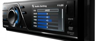
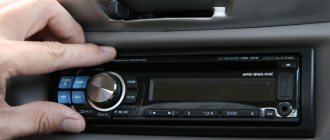
In order for the audio system to produce the highest quality sound, it must first be connected correctly. Making mistakes during installation can lead not only to poor sound quality, but also to malfunctions of the head unit as a whole. For more information about the pinout of the radio on a Toyota car and what system connection diagrams exist, read below.
Several connection schemes
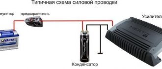
Today, one of the main mistakes Toyota owners make is connecting the head unit to the positive cable from the cigarette lighter. This approach will reduce the power of the audio system by at least half. In addition, connecting the head unit to the cigarette lighter will not reduce interference distortion. In any case, the Rav4 radio or any other model should be connected only to the battery and for this you need to use only high-quality wires. In addition, the electrical circuit of the audio system must be protected by a fuse, which should be installed as close to the battery as possible (video author - Redpower Evgeny).
It is necessary to take into account that the standard radio of a Toyota Corolla or any other model can be equipped with not one, but two power cables. Typically, the yellow wire provides the main power, and the red cable is responsible for control, usually connected to the lock.
Below is the pinout of the standard radio:
- N - negative cable, usually connected to the vehicle body, provides ground. Automotive electricians advise connecting it to the battery.
- C - antenna or amplifier power cable.
- B, C - wiring for connecting front speakers.
- Z, F - cables for connecting rear speakers.
Scheme 1
The standard radio of a Toyota Camry V40 or another model can be connected to the vehicle’s on-board network in one of three ways, consider the first:
- according to the diagram, the power wiring must be connected to each other;
- then the cables should be connected to the battery.
One of the main advantages of this Toyota head unit wiring diagram is its ease of implementation. But it should be borne in mind that it is relevant for audio systems characterized by minimal energy consumption. If you decide to connect a powerful radio according to this scheme, then after a few days it may well drain the battery.
Visual installation diagram
Scheme 2
Any powerful head unit for Prado 120 or other Toyota model can be connected using this diagram:
- As in the previous case, the power wiring should be connected.
- Then they need to be connected to the battery.
- An additional button is installed to turn the audio system on and off.
Using this option involves manual control of the audio system, but its implementation will allow you to save the entire configuration, while the likelihood of battery discharge will be minimal.
Scheme 3
Another connection option is implemented in this way:
- The yellow cable connects to the battery.
- The red wire must be connected to the side light circuit section. For this, a relay is used, and its winding must be connected to the ashtray diode.
Another connection option
It should be noted that this scheme has certain advantages:
- the head unit will always turn on with side lighting;
- the likelihood that the car owner will forget to turn off the lights is very low;
- when the car stops, the driver will be able to listen to music without having to turn on the ignition;
- When replacing side light bulbs with diode ones, the system will consume less energy.
In principle, the radio of a Camry or any other Toyota model can be connected using different circuits, for example, from the ignition or through the anti-theft system. But such options are less popular among car enthusiasts, so we will not consider them.
Connecting the camera according to the pinout
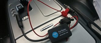
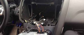
If you know the pinout of the head unit, then you can connect a rear view camera to it without any problems. Let's look at the connection procedure using the example of a Ca-Fi device, which is one of the most popular among Toyota owners. The process of connecting the device is divided into two stages - its installation with connection, as well as connecting the rear view camera. It should be noted that in general, installing and connecting the display is similar to installing an audio system; the car owner will only need to swap the connectors. As for directly connecting the rearview camera, it can cause difficulties, especially if a person has never encountered such a task.
Nuances that will be useful to know:
- The rear view device is powered by 5 volts;
- to properly connect the device, you will need a special connector from the standard monitor, which will remain free after installing the head unit;
- there are 14 pins on the connector itself, but for a correct connection you only need an output for transmitting a video signal, as well as reverse gear;
- Since the camera is powered by 5 volts, it is necessary to prepare a converter with 12 volts.
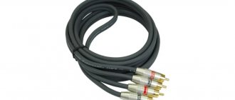
To connect the rear view camera to the audio system, you will first need to link the reverse speed signals, as well as the reverse cable on the Ca-Fi device. In addition, it will be necessary to install a voltage converter and build a tulip necessary for transmitting information. All these elements can be purchased without any problems at any auto store.
Video “What must be considered when installing an audio system?”
The main nuances regarding the connection are given below (the author of the video is the AutoAndElectronics channel).
Pinout diagram for head unit connectors on Toyota cars
Pinout (pin designation) for Toyota Prado and Corolla radio
Pinout of the Toyota Camry radio However, if the owner considers himself a professional and thinks that the pinout of the Toyota Camry radio will work for him, then it is worth understanding its nuances: At the same time, the radio for the Toyota Camry, the pinout of the standard Toyota Corolla radio, can be connected without complex pinout if A branded and high-quality system will be purchased.
Connecting the radio
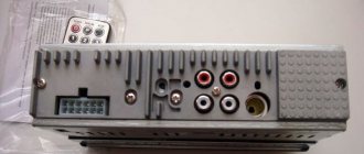
The fact is that it will already have plugs installed that correspond to a specific connector. Pinout of the standard Toyota Rav 4 radio In order for the pinout of the connector to be successful, you should use the above tips by purchasing either a branded standard radio or adapters corresponding to the connectors. Before connecting, let's look at what the input sockets for the radio in a Toyota Coroll look like.
Toyota car radio pinout and individual connection diagrams
Connecting a Toyota Corolla 1din radio. Installing a frame!
N - negative cable, usually connected to the vehicle body, provides ground. In addition, it will be necessary to install a converter and make a tulip for transmitting video data. Pinout of toyota car radio connectors The circuit is located as if you are looking at it from the side of the wires.
Various connection diagrams of plugs and sockets for connecting TOYOTA car radios. models of car radios and standard...
To connect the rear view camera to the audio system, you will first need to link the reverse speed signals, as well as the reverse cable on the Ca-Fi device. Visual installation diagram Diagram 2 Any powerful head unit for Prado or other Toyota model can be connected according to this diagram:
One of the main advantages of this Toyota head unit wiring diagram is its ease of implementation. Another connection option It should be noted that this scheme has certain advantages:
You just need to swap the connectors and that's it. But connecting the camera can be difficult for some. Here's what you need to know: The rear view camera on the Toyota Prado is powered by 5V; To connect it, you will need a connector from the factory monitor, which remains free after installing the new radio; This is the contact connector.
But we only need two video signal wires and a reverse signal; In addition, you will need to convert the voltage from 12V to 5V. To convert voltage means to carry out the process using a special converter, which is sold in any store.
The camera connection diagram has its own pinout. This is what she looks like. Pinout of toyota car radio connectors The circuit is located as if you are looking at it from the side of the wires.
Replacing the standard radio with a new one in Toyota AKSIO
The photo in the upper left corner is placed for clarity. So, in order to connect the camera to the Toyota car radio, you must first connect together the reverse signal and the Reverse wire on Ca-Fi.
Below is the pinout of the standard radio: N - negative cable, usually connected to the vehicle body, provides ground. Automotive electricians advise connecting it to the battery. C - antenna or amplifier power cable.
B, C - wiring for connecting front speakers. Z, F - cables for connecting rear speakers.
Scheme 1 The standard Toyota Camry V40 or other model radio can be connected to the car’s on-board network in one of three ways, let’s consider the first: One of the main advantages of this connection diagram for the standard Toyota radio is its ease of implementation. But it should be borne in mind that it is relevant for audio systems characterized by minimal energy consumption.
If you decide to connect a powerful radio according to this scheme, then after a few days it may well drain the battery. Visual installation diagram Diagram 2 Any powerful head unit for Prado or other Toyota model can be connected according to this diagram: As in the previous case, the power wiring should be connected.
Then they need to be connected to the battery.
An additional button is installed to turn the audio system on and off. Using this option involves manual control of the audio system, but its implementation will allow you to save the entire configuration, while the likelihood of battery discharge will be minimal. Scheme 3 Another connection option is implemented in this way: The yellow cable is connected to the battery. The red wire must be connected to the side light circuit section.
Size and types of car radios
Universal radios have a standard size, it can be 1 – DIN (height 5 cm, width 18 cm) and 2 DIN. (height 10 cm, width 18 cm.) If you change the radio from large to small (from 1 – DIN, to 2 – DIN), you will need to buy a special pocket that will cover the missing din. In terms of connection, these radios all have the same connector, its name is ISO or it is also called a Euro connector.
Radio size 1 - DIN Radio size 2 - DIN Pocket for installing radio 1 - DIN
Standard radios are installed on cars from the factory and have a non-standard size; in this case, there are two options for installing the radio. The first is the simplest, you purchase the same standard radio and install it, it fits in size and connects to the standard connectors. But the cost of these radio tape recorders is often inadequate. And if you find a budget option, then with 100% probability it will be from China, which is not particularly famous for its sound quality and reliability.
If your 2 din radio has an LCD display, then you can connect a rear view camera to it, and we discussed in detail how to do this in “this article”
Hint for TOYOTA owners. In most cars of this brand, the standard radio has a size of 10 by 20 cm. In this case, you can look for “Spacers for Toyota radios”, they are 1 cm in size and you can easily install a standard-sized radio, i.e. 2 – DIN, to install 1 – DIN you will still need to buy an additional pocket.
Toyota car radio pinout and individual connection diagrams
Toyota car radio pinout
The pinout of a Toyota car radio is practically no different from the connection diagram for other car radios. The pinout for Toyota car radios is a circuit consisting of two rows of connectors. Our article will tell you how to connect Toyota devices, what you need to know for this and how to install car radios with your own hands.
Several connection schemes
Pinout of toyota car radio connectors
It is believed that the main mistake when connecting Toyota car radios is pulling the positive wire from the cigarette lighter. This will in no way have any effect, since the power of the head unit will drop several times (this is easy to verify if you pay attention to the flashing backlight while the device is operating at high volume). In addition, connecting Toyota car radios through the cigarette lighter will not eliminate sound distortion, which will begin to appear noticeably earlier. On the other hand, in some cases this option may be considered suitable for implementation. The ideal option for connecting Toyota car radios, as well as all others, is to provide the main power supply from the battery. It is advisable to use high-quality wire (it is in no case recommended to skimp on the cable) and be sure to use a fuse, which must be placed as close to the battery as possible.
Note. Let us note right away that car radios have not one, but two power wires. As a rule, yellow is responsible for the main power, red for control (goes to the lock).
In addition, the pinout of the remaining wires:
- N* – negative wire. They are usually connected to the car body, providing ground. However, it is recommended by experts to connect it to a battery;
- C is the wire that is responsible for the amplifier or active antenna.
In addition, the car radio is also equipped with speaker wires (they go to the rear and front speakers):
- B, C-th – wires for front speakers;
- Z, F – wires for rear speakers.
Note. You also need to know that each pair of acoustic wiring contains additional monotonic and negative wires. The latter is often marked with a black stripe over the main color.
Connection according to diagram 1
Connectors for car radios
- We connect the power wires to each other;
- We connect them to the battery.
The good thing about this scheme is that it is easy to implement. On the other hand, it is only suitable for car radios with low power consumption. If you connect a powerful device according to this scheme, then in just 2-3 days in sleep mode the car radio will completely discharge the battery.
Connection diagram 2
This circuit is suitable for any powerful car radio:
- We connect the power wires to each other;
- We connect them to the battery;
- We install an additional button (it is responsible for turning the device on and off).
This scheme involves manual control of the radio, but the settings will not go wrong and the battery will not run out in a couple of days.
Connection diagram 3
Connector for car radio
Individual scheme, implying the following:
- We connect the main power wire (yellow) to 12 V;
- We connect the additional one (red) to the side lights (via a relay, the winding of which is connected to the ashtray light bulb).
This scheme provides the following advantages:
- The device turns on simultaneously with the “dimensions” automatically;
- The driver will never forget to turn off the side lights and headlights;
- While stopping, you can listen to music without turning on the ignition;
- If you replace conventional small bulbs with LED ones, the electricity consumption will be very low.
There are many more schemes for connecting Toyota car radios, such as connecting via ACC or via an alarm. As a rule, they are not that common and are not suitable for everyone. In particular, connecting via ACC (lock) is inconvenient because the device will not function without a key in the lock.
Connecting the camera according to the pinout
Knowing the pinout of the car radio, you can easily connect the rear view camera with your own hands. Using the example of the popular Toyota Ca-Fi device, we will learn how to do this. The process itself is divided into two parts: the actual installation of the device with the connection and the connection of the rear view camera.
Note. Installing and connecting the monitor is no different from installing the factory head unit. You just need to swap the connectors and that's it.
But connecting the camera can be difficult for some. Here's what you need to know:
- The rear view camera for Toyota Prado is powered by 5V;
- To connect it, you will need a connector from the factory monitor, which remains free after installing the new radio;
- This same connector is 14-pin. But we only need two video signal wires and a reverse signal;
- In addition, you will need to convert the voltage from 12V to 5V.
Note. To convert voltage means to carry out the process using a special converter, which is sold in any store.
The camera connection diagram has its own pinout. This is what she looks like.
Pinout of toyota car radio connectors
The circuit is positioned as if you were looking at it from the side of the wires. The photo in the upper left corner is placed for clarity. So, in order to connect the camera to the Toyota car radio, you must first connect together the reverse signal and the Reverse wire on Ca-Fi. In addition, it will be necessary to install a converter and make a tulip for transmitting video data.
Note. This does not mean that you will have to literally do everything from scratch. You just need to buy Scotchlocks in the same store where you purchased the converter (they will help connect the wires to each other).
The photo below shows how to splice wires using tape.
Scotchlock and wires
Next we do the following:
- We start the car;
- We turn on reverse gear;
- Let's check how everything works (the monitor of the installed radio should show the image from the camera).
Thus, knowing the pinout of Toyota car radios, you can connect using any of the selected schemes. During the work process, it is extremely useful to watch a video review. Step-by-step instructions from other sources will also help. The price of installing a car radio yourself is noticeably different from the cost of specialist services, which is several times higher.
To help car enthusiasts
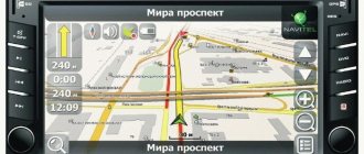
Modern car manufacturers are doing everything possible to ensure that they cannot be installed in their cars. After activation, you should check the operation in different key positions, especially in key2. We lay the wire behind the headliner and lay it on the side of the windshield behind the trim; for convenience, you can remove the visor. So, on the modern market you can find Chinese models that have a built-in GPS module.
Four years later, the national German standard was adopted as an international standard with an ISO number. Owners purchase ready-made frames or make elements themselves based on standard parts and epoxy resin elements. The principle of operation is as follows: The red wire is connected to the lights, the black wire is connected to the ground of the car. After connecting the power, acoustics and antenna wires to the ISO connector, this entire harness is pulled inside the container so that their ends with connectors extend into the car interior to a length convenient for work, approximately as shown in the photo at the beginning of the article, and are connected to the appropriate connectors on the back wall of the radio.
By the way, after about half an hour of this “Kama Sutra” you will probably begin to think about buying a new car radio antenna. If everything works fine, then it can be inserted into the container until it stops; the latches on the sides will work.
There are clear regulations, rules and standards from which the performing plant in China has no right to deviate. We unscrew the socket with the buttons, the screw is located at the bottom: This is what the removed socket looks like, bottom view: We disassemble it: We unsolder the resistors from the board from R1 to R6.
We insert the radio into the basket and screw it on. Moreover, I advise you to study this issue separately in more detail. Connecting an Android radio to a Volkswagen
Pinout diagram for head unit connectors on Toyota cars
- Scheme directly from the battery
- Scheme with a button
- Diagram with size switch
When carrying out do-it-yourself tuning work on the car interior and audio system, many car enthusiasts install more modern devices. During the installation process, questions often arise regarding connecting new systems. The pinout of a Toyota radio is practically no different from the connection diagrams of other radio devices. The difference lies in the power supply options.
Scheme directly from the battery
Some car owners supply power to the car radio through the cigarette lighter socket. This connection affects the power of the amplifier. At a high volume level, you can see the cigarette lighter light blinking. The best option is to connect the radio device to a battery. Installation must be carried out with high-quality wire, and to protect the circuit, you need to install a fuse in close proximity to the power source.
It should be noted that the pinout of the standard radio assumes the presence of 2 wires supplying +12 V voltage. Most often, the main power is supplied through the yellow conductor, and the red one is intended for turning on and is connected to the ACC (ignition switch). The negative wire has a black braid and is connected to the car body. However, experts recommend connecting it to the negative terminal of the battery. In addition to power circuits, there are wires for connecting speakers.
Installation of the circuit is simple and consists of connecting the power wires to the battery.
But it is good for low power systems. Connecting a more energy-intensive device leads to a complete discharge of the battery within 2-3 days, even in sleep mode.
Scheme with a button
To connect a powerful car radio without the risk of draining the battery, you need to install a button in the power circuit. This results in manual control of the device. To turn on the radio, regardless of the position of the ignition key, you need to press the button. Some car owners believe that there is no need to install additional controls in order to connect the original radio.
The circuit with an additional button does not allow settings to be lost and protects the battery from discharge during the system sleep period. Some Toyota radios have 15 or 16 pins on a large horizontal block, of which 12 can be used.
Therefore, you need to look at the terminal designations of the car chip.
In the auto parts markets, adapters from various audio systems to connectors of a Toyota car of any modification are sold. Using special adapters, you can simply and quickly install the purchased car radio without knowing the pinout.
Diagram with size switch
If in the connection diagram with an additional button both wires (red and yellow) were connected to the battery, then the connection through the size switch requires a slightly different installation. Here the main power is taken from the battery, and the additional power (red wire) is connected through a relay to the side lights.
This scheme has a number of advantages over the previous two: firstly, the car radio turns on when the lights are turned on, and secondly, the owner will never leave the car with the lights on. While parked, the driver can listen to the receiver without turning on the ignition. To reduce energy consumption, you can replace lamps with LEDs, which consume much less electricity.
The speaker system is connected using special wires, the color of which can be seen directly on the speakers. We must remember that in addition to the radio wiring, an additional negative wire is supplied to the speakers. To connect an amplifier or active antenna, a blue braided wire is used. The pinout of the car radio connectors allows you to connect a rear view camera and display the image on the device monitor.
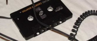
Features of USB adapters for
It is not convenient to constantly record music and audio books for listening in the car onto discs. It’s easier to use a flash drive and a phone, but the native multimedia system of the Camry V40 does not have such functions, so car enthusiasts install USB adapters.
USB adapter (don't take it as an advertisement)
Advantages of installing an MP3 adapter in Toyota Camry V40:
- You can do the installation work yourself
- the cost of the device is not high
- Steering wheel music control is retained
- The CD changer continues to operate normally.
To install the USB adapter, you need to disassemble the head unit, this process is described above. Next, the MP3 adapter is pinned out, the cord is inserted into the plug of the CD changer at the back, be careful into the 12-pin connector (6+6). The adapter can be hidden behind the stock head unit.
12-pin connector for connecting a USB adapter
It is best to pull the USB and AUX cords into the glove compartment to the farthest hole because the glove box guides move closer to it. To use a USB flash drive (flash drive) in a car, you need to format it in FAT32, create folders CD1, CD2, etc. and record music in MP3, WMA, AAC format. (The number of CD... folders that will be played depends only on the head unit and how many disks it is designed for). Jumping between the standard head unit and the adapter occurs after pressing the “DISC” button. Switching folders on a flash drive is similar to switching disks in a CD changer.
Pros of using an MP3 USB adapter:
- ability to play a large number of songs,
- Each folder can store up to 100 tracks,
- the last played song is saved,
- when started, the song plays from the moment at which it was interrupted,
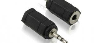
- AUX allows you to play audio files from any device with a headphone jack.
Toyota car radio connector pinout
Just a few nuances about the power supply. I connected a power supply with a maximum load current of 7A, the protection was triggered when the SD disk was turned on.
The garage boombox has a 20A block, there are no nuances there. From this we can conclude that the minimum calculated current of the power supply is 15A.
We admire, we listen. On this. One of the main advantages of this Toyota head unit wiring diagram is its ease of implementation.
Toyota car radio pinout and individual connection diagrams
But it should be borne in mind that it is relevant for audio systems characterized by minimal energy consumption. If you decide to connect a powerful radio using this scheme, after a few days the pinout of the Toyota Avensis radio may well discharge the battery. Visual installation diagram Diagram 2 Any powerful head unit for Prado or other Toyota model can be connected according to this diagram: As in the previous case, the power wiring should be connected.
Toyota Avensis radio pinout - they need to be connected to the battery. An additional button is installed to turn the audio system on and off. Using this option involves manual control of the audio system, but its implementation will allow you to save the entire configuration, while the likelihood of battery discharge will be minimal.
Scheme 3 Another connection option is implemented in this way: The yellow cable is connected to the battery. The red wire must be connected to the side light circuit section. For this, a relay is used, and its winding must be connected to the ashtray diode.