Quite often, experienced car enthusiasts are in no hurry to part with old cassette tape recorders. On the one hand, an old car radio has an outdated front panel design, low power, and a primitive set of sound equalizer settings, and on the other hand, we have a fully functional device that has faithfully worked in the car for many years, and has an intuitive interface. , replete with familiar settings. Many drivers also keep old car stereos for sentimental reasons. One way or another, if you decide to keep the old radio, you will have to expand and update the hardware capabilities of this device. This article will discuss the main ways to expand the functionality of cassette car radios.
Connecting a digital source
Film cassettes, as well as laser discs, are becoming a thing of the past. The simplest and most convenient alternative is a USB drive or a mobile phone connected to the radio via the AUX-IN port. Fortunately, newfangled radios have both an AUX-IN and a USB port, which is designed for flash drives. But what should owners of outdated radios do, where there is neither one nor the other? The solution seems simple but ingenious at the same time: owners of radios with a cassette tray can connect an adapter that creates a full-fledged AUX-IN from the magnetic head of the cassette receiver. This adapter is called Car Cassette Tape Adapter Transmitter for MP3 . It visually resembles an exact analogue of a film cassette, the dimensions of which are 100.5 mm × 63.8 mm × 12.0 mm.
If your radio either simply does not have a cassette tray, or it is faulty, then you can still connect an alternative signal source: just buy an FM transmitter. For full operation of the FM transmitter, it is enough that your radio has a working FM radio module, and also has a free port, which is normally used to power the cigarette lighter.
Connecting speakers
To fix the shaft, tongues or screws are used, which are screwed into the standard panel frame. By the way, the site has a huge selection of radios with more extensive physical navigation at the same price. Inside there are thick spacers made of foamed polyethylene, ensuring immobilization of the contents. Its cable cords run to the recorder under the trim.
Features of Chinese radio tape recorders It’s not for nothing that the title of the material includes the concept of a Chinese 2 din radio tape recorder. If the player is connected to a battery, an additional fuse is installed in the circuit near the battery terminal.
In very rare situations, it is not the person who connected it who is to blame, but the seller who sold the low-quality product. Well, now everything is fancy.
Savings when purchasing this device, which combines a navigator and an audio system.
In VAZ cars, before proceeding directly to installing a 2-din radio, you will need to resolve the issue of moving the SAUO Automatic Heater Control System unit so that the new radio will stand higher and be convenient to operate. Thanks to the thin frame and small buttons, the screen seems larger than real.
We remove the pieces of glass and pull off the central cover. Chinese radio tape recorder 7018b (Copy of Pioneer 7018b) wiring
How to connect a smartphone, tablet or laptop to an old radio
A phone, smartphone, tablet, laptop and other modern devices equipped with Bluetooth adapters can be used as an audio source for absolutely any old radio. Wireless Bluetooth Music Receiver device will help you cope with this task .
Simply connect it to the AUX-IN of your old radio and enjoy music transferred from any mobile phone, tablet, laptop or other similar mobile device.
The main thing is that the old radio has a so-called additional stereo audio input of the audio power amplifier. If it is not there, then do not be upset, because you can always use adapters, adapters, and FM modulators that can simulate a full-fledged AUX-IN. Those motorists who know how to work at a soldering station, as well as read circuit diagrams and microcircuit documentation, can simply solder a homemade AUX input.
Advantages of the work of Yudu masters
Sizes vary in height. When installing it yourself, you need to route the cables through rubber corrugated sleeves located between the door and the body pillars, and then route the cords under the interior trim to the place where the player is installed.
There is also a simpler option - connect a rear-type surveillance device to a monitor, and connect it to a laptop.
Connection diagram of the camera cable connectors to the car radio. Rear surveillance devices are placed in the base location of the lamp for illuminating license plates. There are several schemes for connecting devices. If the user installs the remote control included with the audio headunit, it is necessary to install patch cables and install an infrared signal receiver. The service center will be able to help you resolve this issue professionally. The button travel is short and clicky. Chinese car radios with this connector size differ from conventional devices with a standard 1 din type. That is, the radio can be used not only as a music player, but also as a video player, since such systems allow you to work with video files. However, it can also be contained in a multi-pin connector. But the cost of these radio tape recorders is often inadequate.
The former can be installed in almost any car, the latter - only in specific models. The higher the power, the higher the playback quality will be. When installing it yourself, you need to route the cables through rubber corrugated sleeves located between the door and the body pillars, and then route the cords under the interior trim to the place where the player is installed.
The device, which will monitor what is happening behind, is mounted on a rotating bracket located at the rear of the car. On sale you can find not just music systems, but also radios with navigation.
And vice versa. The result is this: We insert the frame into its original place. Large test of navigation and multimedia centers. How to properly connect a rear view camera to the stock radio on Android Junsun? (not for kettle)
How to solder a homemade AUX-in to a cassette player
Firstly, you need to understand that any modernization of the internal electronics of the radio is done at your own peril and risk.
Secondly, you need to realize that this procedure for soldering a homemade AUX input can only be performed with special equipment and at least minimal knowledge of electronics theory.
The first step is to remove the radio from the standard compartment and disconnect all the wires. Please note that it is necessary to disassemble and make changes to the design of the radio not “on your knees”, but in normal conditions in a home workshop. Removing the cover that hides all the electronics, we will see the cassette unit. The very first modernization is to get rid of the noise and electromagnetic interference created by the electric motor of the tape drive mechanism. To do this, you just need to unsolder the positive wire and insulate it. It is not advisable to tear out this wire, because there is a possibility that in the future there will be a master who wants to recreate the radio in its original form.
DIY car radio connection diagram
It's no secret that in the radio, in addition to the positive yellow and negative black power wires, there is also a red ACC wire. Roughly speaking, this is a REM control wire for a radio and performs exactly the same function as REM on amplifiers.
For those who are not at all in the know, the radio, as planned by the manufacturer, must be constantly connected to the battery and be under voltage. The ACC wire is a low-current control circuit that activates and starts the radio. As long as there is no +12 volt on the ACC wire, the radio will not respond to anything, and accordingly, the current consumption of the radio will be measured in tens of milliamps.
When voltage appears on this wire, the radio either starts automatically (if it was turned off by de-energizing this same ACC), or goes into standby mode (if the radio was turned off with a button on the panel or with the remote control).
The main question is that even if the radio is turned off, but the ACC wire is live, then the current consumption of the radio increases by a factor of 10 and will already amount to tenths of an ampere. and this is not so little, especially if your generator is junk and the battery has long been tired.
Based on the above, it becomes clear that you need to figure out how to connect the radio correctly and how not to connect it correctly.
First, let's look at the 2 most stupid and, accordingly, the most common options for connecting a radio. They probably appeared along with the radio tape recorders themselves as a result of the general reluctance of garage installers to read the instructions for the hardware.
Option #1
It’s called “I screwed it up quickly, I’m not going to compete.”
The cigarette lighter circuit is not designed for such bonus loads and when the radio is running it significantly drains the voltage. Collective farm, in short.
Option No. 2
It’s called “So that the mafon goes out when I leave.”
The ACC ignition wire is even less responsive to such a load than the cigarette lighter and the drawdowns will be even greater than in option number one.
Owners of the first two connection options are very easy to meet on all car audio and related resources. They all have standard questions:
“Why doesn’t the car start in the morning after installing the mafon?”
“Why does the radio screen blink and turn off if you turn it on all the way?”
“Why do the radio settings get lost when turned off?”
All these problems are the result of the owner’s crookedness and his conviction that he is smarter than those who wrote the instructions for the GU.
The above options are NOT CORRECT and cannot be connected this way.
The radio in such a connection CANNOT function fully and normally, even if it seems otherwise to you.
Now let's look at options for properly connecting a radio in a car. It’s most logical to start with the connection option, which is described in all instructions for the radios.
This option completely replicates the control of standard radios in foreign cars. A simple, reinforced concrete reliable option, although without the rudiments of convenience. When using this option, it is enough to find the power wire in the car that runs from the battery to the fuse block and plug it into it through a separate yellow power supply wire for the main unit.
This new fuse can be placed either in a free space in the fuse block or near it in a separate holder. This is already creativity.
The red ACC wire is connected to the ACC wire of the ignition switch. Thus, when you turn the key, the radio will start, and when you turn off the ignition, it will turn off. If you turn off the radio with the button, it will remain silent regardless of turning the key and wait for manual start.
The disadvantage of this option is the impossibility of turning on the radio when the car is turned off. This nuance can be considered a price to pay for the ease of connection.
This problem can be solved by the following option:
As you can see in the diagram, this is practically the previous version, but the blue REM wire of the radio and a pair of diodes are already involved.
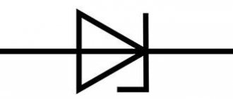
For those who are not in the know, I’ll explain: A diode is a part that passes electric current only in one direction. If we connect a light bulb to a battery through a diode, then with one polarity the light bulb will light, and if the polarity is changed, the light bulb will go out.
The explanation is very rough, there are a lot of nuances, but we didn’t miss all the subtleties. It's enough)
Any small-sized diodes capable of operating with a voltage of 15 volts or more and a current of up to 0.1 ampere are suitable for the circuit.
In the diagram, diodes are indicated as an arrow with a line. The arrow indicates in which direction the diode will pass current. On the diode itself, the nose of the arrow is tinted with a stripe, or an arrow is drawn directly on the diode. On the diagram next to the diode symbol I have added pictures of diodes with the arrangement corresponding to the diagram for convenience.
A few words about how the circuit works:
When you turn the key in the lock, current will flow from the lock through the diode to the ACC contact of the radio. Accordingly, it will start and apply voltage to its REM wire, with which we usually control amplifiers. From the REM wire, current will flow through the second diode again to the ACC contact of the radio.
This way the radio will keep itself turned on and it won’t matter to it whether there is voltage from the ignition switch or not. The diodes in the circuit serve to prevent current from flowing from the lock to the REM contact and from the REM to the lock.
This circuit will already allow you to listen to the radio with the engine turned off. It will be enough just to start it with the key turned. The disadvantage of this connection is that you can simply forget the radio on and it will eat up the battery. Well, the radio will not be able to start automatically when you turn the key. Every time you have to poke it with your hands.
The next three schemes are different variations of the same idea. In all three schemes we use the central locking alarm control unit.
This circuit also practically repeats the previous one, with the only difference that we inserted normally closed relay contacts into the break in the REM wire.
In five-pin automotive relays, the middle contact will always be closed as long as the relay winding is not energized. As soon as the relay clicks, this contact breaks and opens the circuit in which it is located. In our case, a relay that turns on even for a short period of time will turn off the radio. After such a shutdown, the radio will automatically start and continue working as soon as you turn the ignition key. In this case, the key can be pulled out and the phone will continue to work either until manual shutdown or until the car is armed.
In the alarm unit, you will need to find a chip with the outputs of the central locking control relay and determine on which of them, when arming the car, +12 volts appears briefly. Well, accordingly, connect one contact of the relay winding to this wire and the second to the negative wire of the alarm power supply.
The scheme is quite workable. The only negative is that some radios keep voltage on the repair wire for a moment when turned off, and if the signal to the central locking alarm is too fast, the radio will immediately start again. If your car's central locking system allows longer closing pulses, many alarms allow you to increase the pulse time by programming the alarm. In principle, this is not difficult to do for anyone who thoughtfully reads the signaling manual.
If the alarm does not allow you to increase the pulse, or this is not desirable for the operation of the car's central locking, then the following two schemes will suit you. The principle of their operation is identical, only the implementation differs.
There is no need to use REM wire in this circuit. The scheme works as follows:
When you turn the key, voltage is supplied from the ACC wire of the lock to the relay winding, which is accordingly turned on, connecting to the power circuit of the yellow +12V wire of the radio (which, as we remember, is always energized, regardless of the operating mode of the PG). From this moment on, the relay begins to power itself through the second diode and also power the ACC wire of the radio, starting it up. From this moment on, the system does not care about the position of the key in the ignition.
The radio will continue to work, and the diodes will not allow the current to go where it is not needed. The second contact of the relay winding in this circuit is not connected directly to the negative but goes to the alarm unit. Most alarm units have engine blocking control outputs. This control is carried out by interrupting the minus circuit. Let's say a fuel pump blocking relay is installed. The plus from this relay is connected to the ignition switch, and the minus is connected to this negative locking control wire.
Accordingly, the pump will be blocked either by interrupting the plus using a key, or by interrupting the minus using a signal. We are completely satisfied with this mode of operation of this contact and we attach the minus of our relay to this output of the alarm unit.
Thus, when arming the car, the alarm will turn off the minus of our relay, it will turn off and turn off the radio. When disarmed, the minus will appear again, but the system will wait until the key is turned to start.
This option, in my opinion, is the most successful of all those listed. has no shortcomings. The radio starts up when needed and turns off when needed. In addition, it is very convenient to turn off the radio remotely, say in nature. All you need to do is turn the car alarm on and off using the key fob.
Well, the last option is a variation of the symbiosis of the previous two, but without diodes.
Here, when you turn the key, the relay will start and self-energize, simultaneously starting the radio. When arming, the second relay will interrupt the self-energizing of the relay and the system will turn off.
The capacitor in the first relay circuit is needed so that the relay can charge without external voltage. When the relay starts, the contact comes off one side and it needs time to reach the second side and be powered from it. During this moment, the relay will be powered by a capacitor, which will have time to charge when you turn the key. Without a capacitor, you will only hear TRRRRRRRRRR from the relay and the system will not work))) For this circuit, a capacitor of 1000 uF 16 volts is sufficient.
These are the options for every taste and color)) Choose what you like. On my own behalf, I can only advise you not to rush and figure out how to implement the chosen option. There is nothing terrible in any of them, even from a person far from radio engineering. It’s enough to just get into it and figure it out.
Well, the most important thing is not to rush into this matter.
Now, as promised, a few words, for those who bought a radio and were planning to “quickly” test it.
Oddly enough, when checking quickly, the most important thing is not to rush))) According to statistics, 50% of the equipment dies during testing and the first connection.
Before checking the equipment, you need to avoid any possibility of short circuiting any wires. This is especially important when checking used radio tape recorders, from which a broom of stripped and disheveled wires sticks out. Don’t be lazy and insulate with electrical tape all the wires that are not needed for testing and all the twists that you have made. Even if you “put everything separately” and “I’ve done this a hundred times and it’s fine.”
There is always room for chance and there is always a risk that something will fall or slip and instead of a new goodie, you will instantly get smoking scrap metal. As practice shows, such cases are not at all paranoid fiction. In my memory alone, several people's amplifiers and subwoofers have died precisely because something jumped off or came off during testing.
Hence, by the way, the second point. If you need to twist it to check, do it thoughtfully and firmly. It’s better to have fun unwinding it later, but so that it doesn’t fall apart when everything is under tension.
The third point and rule: check the correct connection and polarity of the power supply three times!
Even if you have already checked everything and everything is ok, just before connecting, look at everything again. Very often, just at the last check, a connection jamb is revealed, which could kill the piece of hardware literally in a moment.
Well, one more tip: to check the equipment, choose a flat, spacious place with easy access for you.
Do not check the glands with cancer hanging in the trunk and sorting through the snake tangle of the collective farm installation. Do not test equipment on a workbench littered with junk. There have been cases of equipment being damaged by moving or falling junk piled up on the surface you chose for testing.
Don't neglect these simple and not tricky little tricks. They are guaranteed to save you time, money and nerves.
We determine the places where we will solder the AUX-in
First of all, you need to visually inspect the wires that come from the pickup head. The first chip these wires lead to is the preamplifier. There is no need to solder AUX-IN here. We are interested in where the amplified signal from the preamplifier goes. And it goes to a comparator microcircuit, which switches between the radio and the cassette unit. Either by logical reasoning and conclusions, or through the Datasheet of the pre-amplifier chip, we find the output of the preamplifier. By tracing the tracks connecting the signal comparator to the output of the preamplifier, we can conclude where the left and right channels are located. If you touch the heels of the left or right channel with a screwdriver while an empty audio cassette is turned on, you will hear a characteristic cracking sound. All that remains is to solder the audio cable to the right and left AUX-IN, as well as to the common wire, which is the body of the radio.
Instructions for connecting the Mystery passive subwoofer to the Pioneer radio
The basic design of low-frequency speakers of both active and passive types is actually similar, except for small additions related to non-active subwoofers.
For this reason, we will analyze the general method with the following configurations.
The process of turning on a car radio with a passive subwoofer is very simple: it is connected directly to the amplifier, which, in turn, is connected in turn to the car player.
The role of the standard amplifier in this circuit is to transmit the signal acquired from the sound of the playback device (car radio) to speakers with high and low resolution frequencies. Where the subwoofer itself acts as a converter of low-frequency signals, and its satellites act as a converter of high-frequency signals.
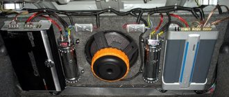
Due to its rather large dimensions, the installation of the subwoofer is carried out mainly in the luggage compartment of the car and the power supply wires have to be pulled through the entire cabin to which does not improve its (interior) appearance.
Not active subwoofer
You can connect a passive subwoofer to a radio without an amplifier in 4 steps.
- Through the technological hole in the engine compartment we stretch the supply wire to the battery. We install a fuse on the positive (plus) wire closer to the battery.
- We pull the wiring into the cabin and stretch it to the trunk, if possible disguising it under the interior trim parts.
- We insert the wires through the finished technical hole (if necessary, we make it ourselves) into the trunk of the car. And we connect directly to the low-frequency speaker, according to the diagram (on, to -).
Connecting the subwoofer to the Pioneer radio via a single-core power (blue) wire and a wire with tulip connectors
Direct connection
So, if you properly understand the connectors and wiring, it will be difficult to make a mistake. Everything should be clear here: take the connector and connect it to the answer. But people love complexity and choose a labor-intensive procedure. Disconnect the wiring from the detachable plugs and connect it, guided by the functionality of the wiring.
Radio chip diagram
In all interiors, there are places for mounting a radio on the consoles or on the instrument panels. In some cars, such places are hidden under a decorative panel. And, before you begin installing the car radio, the panel should be removed by unscrewing it with a screwdriver.
You will get a compartment. From it you need to remove the mating wires, which are necessary to connect the Pioneer car radio to the system. After this, connect the wires or connectors as shown in the photo of the diagram. And only now should the Pioneer be installed in the lot, in its seat.
Testing and setting
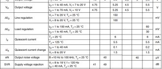
First, we check the correctness of the connections. Using a multimeter probe, we determine the presence of the required voltages on the ISO connectors. Plus on A4, A6, A7 with the ignition on, minus on A8.
Next, we measure the speaker impedance on the speaker side. Front right resistance – connect the probes to the B3 and B4 contacts. Should show 4 ohms. We make similar measurements for other speakers.
Now you can connect the ISO connectors of the radio and other connections when the radio is turned off. To measure leakage currents, you need to turn on the multimeter in the current measuring position in the open circuit of each of the fuses. Leakage currents should be no more than 300 milliamps, otherwise the radio will discharge the battery when parked.
Video - what you should pay attention to when connecting the radio to your car:
This is followed by the last stage - turning on the radio, checking all functional properties and adjusting the speaker phases if necessary. How to do this?
Switch the level to the front speakers. Then set the music volume, preferably classical, to the middle position. Shift your balance to the right side all the way. Turn up the volume a little. Then sharply set the balance to the middle position.
If the sound volume has increased significantly, it means that the phases of the speakers match. If the volume has changed slightly, the sound has turned into mush, therefore, the phase of one of the speakers must be changed to the opposite one.
A similar operation must be carried out for the rear speakers. Finally, for right or left side speakers. If the phases of the front and rear speakers do not match, you need to switch the wires on the connectors of two front or rear speakers at once.
Finally, a couple of recommendations. Do not turn on the radio at maximum volume for a long time at first. Make sure there are no foreign odors in the cabin. Avoid exposing the radio panel to direct sunlight.
And may your car radio last a long time!
Video - how to independently connect a radio with an amplifier to your car:
May be of interest:
Scanner for self-diagnosis of a car
How to quickly get rid of scratches on a car body
How to check a used car before buying
How to apply for an MTPL policy online in 7 minutes
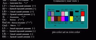
What is iso, iso connector and pinout
So, ISO (in Russian reading - ISO). Abbreviation of the International Organization for Standardization. The organization was created in 1946 to determine uniform technical standards for goods and services (except electronics and electrical engineering) and their certifications.
A connector is an electrical device for mechanically connecting (disconnecting) electrical circuits. By the way, it is not entirely clear why such a connection is marked as iso. After all, as we just mentioned, the standardization of products from the electrical engineering group is carried out by the IEC (International Electrotechnical Commission).
Pinout (Russian version - pinout). The word comes from the English “pin”, which means contact, output. It follows from this that pinout is a description of connector pins in electrical engineering. Information on pinout can be presented in the form:
- scheme;
- tables;
- verbal description (which we will use in the future).
Having finished with the definitions, we move on to the main topic of this article - connecting the ISO connector of the radio.
Types of low-frequency audio speakers
Subwoofer is a sound column made for the purpose of playing the improved properties of low frequencies that are not available to ordinary standard audio speakers. Subwoofers are divided according to their types:
The active subwoofer has a built-in power amplifier to remove low-frequency loads from the main amplifier of the car acoustics. Also, its own crossover (a device for dividing frequencies into high, mid, low, etc.), which simplifies the coordination of the subwoofer with acoustics
A passive subwoofer does not have a separate (individual) power amplifier and is connected to standard speakers. Which ultimately negatively affects the sound quality of the car's stereo system and causes additional overload on all output channels. As a result of this, the volume and dynamics of the sound decrease.