Sections of the article:
Radiotekhnika U-101 stereo amplifier repair
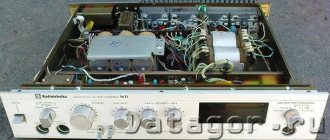
Hello everyone who likes to listen to loud music and repair Soviet sound amplifiers. The other day I came across the Radiotekhnika U-101 stereo amplifier, for only 1000 rubles. The seller complained that there was noise in the speakers and the second channel did not work.
Without thinking twice, I purchased this sound amplifier and soon repaired it. The cause of the noise in the speakers was dried electrolytes at 2000 uF (50 V) and non-working capacitors in the pre-amplifier - there are 6 of them in total, 2 polar and 4 non-polar capacitors.
In general, they won’t get too far ahead of themselves, and I’ll tell you about everything in order...
Contents
The first time I connected her to the network and tried to hear her voice made a depressing impression on me! THIS could not be called sound. Instead of low frequencies - wheezing, plus a 50 Hz background in the speakers, in general - horror. Conclusion: urgent repairs and modernization! Several days on the Internet to search for the necessary information. We draw up a work plan on paper. Let me make a reservation right away: we will restore it to its original factory version. Turn on the soldering iron. Go! First of all, we change ALL electrolytic capacitors. The device is quite old, released on May 25, 1984. Instead of the above capacitors, there were only objects left in it that looked very similar to electrolytic capacitors, but now with completely different functions. Some went into the class of resistors with some resistance, and the other part went into resistors with infinite resistance! We also remove “red clay flags”!
↑ 1. Power supply
Replace the power supply filter capacitors. For the ±26V power supply, I set 10,000 and 4700 uF and for the ±31V power supply, 4700 uF per arm. We also replace the diodes with KD 213. (These and further in the article, the ratings of the parts are not recommendations, since they were used those that were at hand, i.e. at home). At the same time, we change the wires coming from the transformer to the power supply board to wires with a larger cross-section. Considering the power of the amplifier, I limited myself to a cross-section of 0.75 mm2. We shunt it with film. We remove the thin jumper on the power transformer (pin 6-6*) onto two separate wires from each coil to the common point of the power supply board. Next, we hang the capacitor parallel to the primary winding of the mains power supply 0.047 µF x 630 V. Thus, we get rid of interference from the mains a little. Now we have a normal power supply. And this is almost half the road to success.
Radio engineering 101 capacitor replacement
Hi all! I will not introduce this beautiful, legendary Soviet amplifier, but will immediately begin to describe the technology for working on it. The amplifier came into my possession in quite good external and working condition. The appearance of my U-101 Radio Equipment is presented in the photographs below.
Prevention.
First of all, we will talk about prevention. As is known, the most vulnerable element of electrical circuits, which depends on time, is the electrolytic capacitor. It dries out over the years and loses its capacity. Replacing all Soviet electrolytes with new, imported, pre-tested ones - this is the prevention of the Radiotekhnika U-101 amplifier.
Just for fun, I measured the capacity of two 5uF electrolytes that were on the power amplifier boards. I wasn't surprised because I expected it. Instead of 5 µF, the capacitance was about 30 nF, that is, the capacitances were completely dry. I checked the rest out of curiosity and was still surprised that the capacitors on the power supply board had a capacity greater than what was indicated on the can. Nowadays this rarely happens, especially with Chinese capacitors.
Next, I gradually replaced all the electrolytes, leaving the power supply board for later. On it I made several additional holes for mounting several capacitors. As a result, I doubled the capacity relative to the standard one, since the dimensions allow this to be done with a reserve, and there is no such thing as excess capacity. On the +-31V buses, I installed two electrolytes (in each arm), with a capacity of 4700 μF 50V each. And on the +-26V buses I installed two electrolytes (in each arm), with a capacity of 2200 μF 35V each.
I shunted the electrolytic capacitors of the power supply with film capacitors with a capacity of 100-470nF, one for each of the +-31V and +-26V arms.
After the preventive maintenance, the amplifier began to breathe in a new way, as if it had become 15-20 years younger.
Finalization.
Now I’ll tell you a little about the modification of the Radiotekhnika U-101 amplifier. Some craftsmen understand the word “rework” as a rework and throw out all the original guts from the case, but this turns out to be a completely different amplifier...
I will make a few minor changes that will improve the performance of the U-101 Radio Engineering.
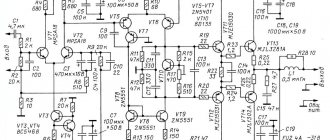
One significant drawback, which was implemented at the manufacturer's factory, is the unstabilized power supply of the tone control unit through quenching resistors R47 and R48 (see diagram). Quenching resistors are well suited in circuits with static loads (for example, for an LED). The tone block has a dynamic load. It is also necessary to take into account the fact that voltage ripple occurs on the +-31V buses at the rated power of the amplifier. Therefore, I added two integrated stabilizers LM7815 (+15V) and LM7915 (-15V), and instead of resistors R47 and R48 I installed jumpers. Thereby providing the tone block of the Radiotekhnika U-101 amplifier with a bipolar stabilized DC voltage of +-15V.
↑ 5. Fighting the background
Got it! No forces! We replace the capacitors in the phono stage with fresh ones. This didn’t give us much, but it won’t hurt for prevention. During the work being carried out, it was noticed that the background increases when you bring your hand to the cable connecting the input board to the pre-amplifier. Yeah! Got a handsome guy! We unsolder the wires from the preliminary input and... silence!!! Exactly him! Only mass screening will help! It would have been possible to run it with separate shielded wires, but I did it differently. We remove the chip from the cable. We find a piece of shielded cable, remove the braid from it, shape it, solder the end so that it does not come apart. Now we carefully insert our train into it. Again we form along the train. We put the chip back. The result is a snake like this. We insulate the screen braid. It’s better to put a heat-shrink tube on top and shrink it. We make a connection to the common wire only from one side - from the side of the signal receiver. We put the cable in place. Turn it on. Fon committed suicide! There is a bit of a sting, barely audible when you turn the volume knob to maximum, but it’s nothing compared to the noise that was there!
Amplifier Radiotekhnika U-101 (Radiotehnika U-101)
Comments (13): #1 Alexander May 14 2022 +5
Good afternoon. Can the protection circuit in the U-101 radio amplifier be eliminated or is it better to have it there? In the amplifier diagram this is board U6. Thank you.
#2 root May 14 2022 +3
Good afternoon. You should not exclude the protection circuit, because if the output transistors of the UMZCH fail or there are problems with the power supply, it will help save your speaker systems from damage.
#3 ALEKSANDER3322 June 07 2022 +1
Hello. Is it possible to rewind windings 3-3 in order to separately power the ends of the AGEEVA amplifier or on the TDA7294 microcircuit. The preliminary ULF will be powered from a 30W transformer and a board on LM317 and LM337 plus or minus 15V. ? THANK YOU.
#4 root June 07 2022 0
Hello. In the Radiotekhnika U-101-stereo amplifier, at the output of rectifier U3 there is a bipolar voltage of plus or minus 26V, which is used to power the final stages of the UMZCH.
Ageev’s UMZCH circuit “Amplifier block of an amateur radio complex (60 W)” also uses bipolar power supply. To obtain an output power of 60W you need plus or minus 28V. This circuit can be connected to the rectifier of the Radiotekhnika U-101 amplifier; there is no need to rewind the secondary windings of the transformer.
#5 ALEXANDER June 08 2022 0
Hello. I wanted to power each channel with a separate winding plus or minus 26V. The terminals in RADIOTECHNIKA U-101 are powered by two bipolar 31V. and 26th century This is very fat - for three microcircuits there is such a powerful winding. Most good amplifiers are powered by one voltage. In my opinion, the Balts were too clever to confuse the Americans. THANK YOU.
#6 ALEXANDER June 09 2022 +1
In all diagrams of the power supply board - U3, the polarity of the diode bridges is incorrectly indicated.
#7 root June 09 2022 0
Alexander, thank you! The designations of diode bridges have been corrected.
Secondary windings 3-4 and 3′-4′ serve as auxiliary windings to produce a rectified voltage of plus or minus 31V, which is used to power the input parts of the UMZCH in the ULF-50-8 blocks, as well as for volume and tone control circuits.
If these windings are wound with the same thick wire as 5-6 with 5′-6′, then they can be used to power the UMZCH. But, most likely, windings 3-4 and 3′-4′ have thin wire and rated currents amount to tens of milliamps.
#8 ALEXANDER June 10 2022 +4
Thank you for the answer. The secondary winding is wound with one thick wire with pins 4-4, for 26V. and 3-3, for the 31st century. I plan to power each end with its own separate winding with its own bridge on KD213A and a filter of 22000 μF. 63V. in each shoulder. THANK YOU SO MUCH FOR YOUR ADVICE.
#9 Sandjar August 07 2022 +4
Hello. Who can answer, when the volume is increased in idle mode, a low-frequency hum is heard in the speakers.
#10 Sandjar August 07 2022 0
Good afternoon. Can you tell me where the wire goes from the (5) terminal of the secondary winding of the transformer? (Radio Engineering u101).
#11 ALEXANDER August 15, 2022 +1
Hello. The wire from terminal 5 goes to the circuit board. - general and on the indicator board 5 pins in shr. - general (building).
#12 serge November 02 2022 0
The protection relay turns off at high volume, tell me what to do?
#13 root November 03 2022 0
Hello. This is how it should be; this was introduced to limit the maximum output power so as not to overload the output stages of the UMZCH. The adjustment can be made by changing the resistances R3 and R4 on the protection board, see the diagram in Fig. 4. If the protection is triggered at low power, check whether the voltages going to the modules from the power supply correspond to the norm.
↑ 6. Final amplifier
During the work, the performance of the amplifier was checked after each change. But it's not the same. I wasn't happy with the sound. Somewhat lethargic. And there is no bass. Just some kind of fart. We measure quiescent currents per channel: 26 mA and 30 mA. Then it dawned on me. That's who won't let me in! In the end of the Balts, current equalizing current sensors R32, R33, R38, R39 = 1 Ohm 0.5 W were soldered in!!! For my speakers, which have a resistance of 4 ohms, an additional two ohms is clearly excessive! White bricks from our yellow-faced brothers will help us here! Change to 0.22 Ohm 5 W. Turn it on. Here it is - dynamics! Here they are - low! The device was kept in place by protection using transistors VT11, VT12. Finally the “girl” started singing!!! She started singing!
Along the way, I replaced the P308 wooden transistors (VT7, VT10), which were clearly not thriving in their characteristics (especially the current - 30 mA), with what I had at home - 2N5551, selected in pairs for each channel.
The conclusions, however, had to be bent - the base and the collector had to be swapped. Next, I set “zero” at the output of the terminals. Before the replacement of P308 it was 77 mV and 110 mV, after the replacement it became 60 mV and 60 mV, respectively. After the replacement, I adjusted R5 (3k9). I installed a resistor with a nominal value of 4k52 (there were such ones) and the outputs became slightly less than 30 mV. On this I calmed down. I could have tinkered with it some more, but I didn’t. I decided that enough was enough. Now the quiescent current!
It was not possible to set the quiescent current normally due to dust-covered, aged trimming resistors. Here my favorite multi-spinners SP5-2 helped me. They had to lengthen the legs from MLT-1 resistors of a rarely used value that had served their time. Solder it in. We shorten the input to ground. Turn it on. We measure. Let's correct it. After a half-hour run and adjustment, I set the quiescent current to 50 mA. (Here we must not forget about precautions. One wrong movement and a “draft”. In this case, to limit the current and protect against troubles, I used 24V car lamps installed in the gap of the ±26V supply wires). The photo shows the check after disconnecting the lamps and the final adjustment.
Setting up the pre-amplifier of Radiotekhniki U-101
Often, happy owners of the Radiotekhnika U-101 amplifier are faced with such a problem as different gain factors of the pre-amplifier channels, or even weak gain. In this article I will describe a method for adjusting the gain factors of the ULF-P board, which must be performed after repair or as part of preventive maintenance. The technique is taken from the device repair instructions ().
What do we need for this?
-Signal generator;
-Oscilloscope;
-Load resistor with a resistance of 4 Ohms and preferably with a power of at least 20W.
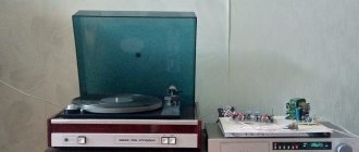
All settings must be performed on a warm amplifier. According to the repair instructions, running Radiotekhnika U-101 is performed at medium volume for at least an hour, only after that it is recommended to start setting up the device. Therefore, we hook up our speakers, sound a beep and listen to music for about an hour.
After the run, you must turn off the power from the device and to its input, for example, “Univ.” submit a sinusoidal signal of 180 mV from the signal generator (sinusoid swing 508 mV). Don't forget to move the input selector to the desired position.
I use a Chinese signal generator, which is ideal for such tasks. My generator is single-channel, like the S1-94 oscilloscope, so I configure the channels one by one.
According to the repair instructions, resistors (Rc) with a resistance of 22 kOhm should be installed parallel to the input, but they are needed to check the background level from the linear inputs, so we do not install them.
The next step is to install a pull-up resistor on the output jacks (to which the speaker system is connected). Its resistance should be 4 Ohms, and the power dissipation should be 20 W. The power of the resistor may be less (5W), but then it must be placed in a bath of water. Or make a rough adjustment without it, and then briefly connect the resistor and make fine adjustments, this is what I did.
An oscilloscope must be connected in parallel to the load resistor.
Turn on the power to the amplifier. We move the power control knob to maximum, the balance and tone knobs to the middle. “STEREO-MONO” switch to the “STEREO” position.
We look at the signal range on an oscilloscope. According to the repair instructions, the output of Radiotekhnika U-101 must be set to a voltage of 8.95V (the swing of the sine wave on the oscilloscope screen will be 25.2V). I set the division price to 5V per cell and set the required value.
The gain is changed by trimming resistors R24 and R26 (each resistor is responsible for its own channel).
When making adjustments, be careful not to short-circuit the outputs. It is advisable to perform all switching operations with the amplifier power turned off. Rotation of the engines R24 and R26 is best done with a dielectric screwdriver.
After setting up one channel, we switch the test equipment to another channel and repeat the whole process.
Amplifier circuit Radiotekhnika U-101
Related materials
Aluminum electrolytic capacitors from EPCOS: Directory…. Aluminum electrolytic capacitors from EPCOS: Directory. Publisher: EPCOS Year... Restoration and modification of the Amphiton U-101-1 amplifier... The first article in the series about resurrections and reincarnations was about "Radio Engineering U-101": Audio amplifier... Capacitors: Directory. G.A. Goryacheva, E.R. Dobromyslov... Capacitors: Directory. G.A. Goryacheva, E.R. Dobromyslov. Publisher: “Radio and Communications” Year... Rectifier and filter unit for UMZCH... In my spare time I started prototyping amplifiers on popular chips and became concerned - what will I do with them... Tweak of the KENWOOD DPF-R3030 CD changer or my first experience with tubes... I purchased this device January 6, 2001. This was my first purchase for my own... Resistors, capacitors, transformers, chokes, switching devices for electronic devices. Akimov N.N., Vashukov E.P., Prokhorenko V.A., Khodorenok Yu.P.... Resistors, capacitors, transformers, chokes, electronic switching devices. Akimov N.N.,... A simple active filter for a two-way amplifier... The article will focus on an active filter for a two-way amplifier. The filter does not need... History of repair and modernization of “Radio Engineering U-101-stereo”... I would like to tell you about my history of repair and modernization of the amplifier “Radio Engineering U-101-stereo”. It seems... USB acoustics Genius SP-U110: where to look for the right sound TDA2822... In this article I want to talk about a way to deal with interference from Genius computer speakers... Another circuit of the Taschibra electronic transformer (Tashibra, Tashibra)... I opened it before reading the article " The use of Taschibra electronic transformers in... Tube amplifier-receiver Fisher-800C. Hello from 1961!... I once went to a friend’s workshop and saw a tube amplifier-receiver among the equipment on the shelf... We are repairing an Acer AL1916 LCD monitor and figuring out how to disassemble the monitor without unnecessary trouble?... This “work” describes disassembly and the simplest Acer AL1916 monitor repair. Since I'm in our...
Amplifier repair Radiotekhnika U-101 stereo - noise in the speakers
The so-called noise in the speakers when connecting the Radiotekhnika U-101 stereo amplifier was caused by dried electrolytes on the power board. There are six of them in Radiotekhnika, 2000 uF each at 50 Volts. When checking the capacitors with a multimeter, it turned out that only 2 of the 6 electrolytes were working, the rest were completely dry.
Accordingly, by replacing the dried out capacitors with new ones, I was able to completely get rid of the “AC voltage” noise in the speakers. If you have the same problem with the Radiotekhnika U-101 stereo or hi-fi amplifier (they are completely identical), then, first of all, you should check the supply voltage and the serviceability of the capacitors.