How I made a budget amplifier using TDA2050 for old speakers
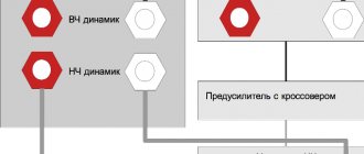
Below the cut is a photo, a description of the process, some diagrams and a detailed description of some aspects of the creation of this miracle. I got my hands on some old Soviet S-50 speakers (if I can get my hands on them, I’d like to modernize them, but for now I have them, that is), their TX:
- Rated electrical power of at least 50 W
- Rated electrical power 25 W
- Nominal electrical resistance 8 ohms
- The range of reproduced frequencies is no longer 40-20000 Hz
And along with them I got a magnificent amplifier Odyssey U-010, which burned out. Having disassembled it, I realized that with my scanty experience, I couldn’t do anything. I Googled a little, looked at specialized sites and here is the solution - we’ll make our own amplifier based on the TDA2050 chip, as a replacement for the old one. For " Handmade and DIY forever"
", and not so difficult. TX TDA2050:
- Rated output power 32W
- Integrated short circuit protection
- Integrated overheat protection
- Power supply up to 50V from a unipolar power supply
(Just a note, perhaps I came across a fake, but during a short circuit, one TDA2050 exploded so that a fragment of a microcircuit left a rather deep wound on my forearm, lucky it wasn’t in the eye, be careful, safety is paramount!)
Frame
First, let's decide on the body. As an option, using the case from the burnt Odyssey U-010 was no longer necessary, due to the size of that case about a small bedside table (460x360x120). Something more compact will suit us. At first I looked towards aluminum cases, but quickly abandoned the idea due to the price of these same cases. The ones I liked started at $100, which doesn’t fit into the “budget amplifier” category. Therefore, an intermediate version of the “temporary” cheapest case was chosen, in which it has been standing for about 6 months. This case was “Z16 Black” (easily found in Google for this request). Dimensions (H/W/L): 89 x 257 x 148
Scheme
Next, it was necessary to decide on the circuit itself, because there are a huge number of them under the TDA2050. The choice fell on the so-called “ Skif scheme
”. And ordinary components, not SMD, became a plus for me, because I had no experience in SMD soldering or a soldering station itself, just a regular 40W soldering iron. So, the circuit itself (the board drawing for this circuit can be downloaded from the link at the end of the article):
I draw your attention to the fact that this circuit requires BIPOLAR power supply. The size of the finished board for one amplifier channel: 35x45mm (and you need 2 of them), which is quite compact as a result.
power unit
So, to power 2 channels of 32 W, we need 64 W (although this is all conditional and could be less). TPP-287-220-50
transformer with a power of 90 VA was lying idle in the bins , and it was easy to remove bipolar power from it. Photo and diagram:
In order to remove 35.26 V AC from it with a midpoint, you need to connect the terminals with the numbers: 12-15, 11-20, 13-18, 14-21, 17-16, and we will remove the voltage with 16, 19, 21 pins. Below is the rectifier diagram:
Here is an example of the board itself. Although I made it by simply drawing it on a textolite with a permanent marker and etching it, without any LUT. It's quite simple.
In the case of the TPP-287-220-50 transformer, you need to connect the 16th output of the transformer to the “middle point” input of the rectifier board. 19 and 21 to the remaining two, which one goes where is up to you, and solder a jumper from the midpoint input to the pad between the capacitors. After connection, you can check the voltages at the rectifier outputs. Between + and – there should be from 42 to 50 V, depending on the network voltage. Between “+” and ground, as well as ground and “-”, there must be the same values. If you don’t have any of the elements for the rectifier, then don’t rush, once we figure out the amplifier board, we’ll go to the radio market to get everything in a bunch. A list of all elements will follow in the text.
Amplifier
To begin with, we etch two boards like this:
And while they are poisoning, we can go to the nearest radio components store or radio market.
So, we need for the entire amplifier:
Power unit:
- Email lytic capacitors minimum 10,000 µF x 25 (or more) V
- Almost any diode bridge, up to 10A (with a huge margin) and more than 50 V. (I took 10A and 400V - it costs a penny)
The amplifiers themselves (everything is calculated for 1 board, respectively, take 2 times more): Electrical capacitors. lytic:
- C7, C8 – 1000uF x 25V
- C3 – 22uF x 25V
Ceramic capacitors:
- S2- 220pF
Film capacitors:
- C1, C4, C6 – 4.7 µF
- C5 - 0.47 µF
Resistors (all 0.125 W, and R6 and R7 2W):
- R1, R3 – 2.2k
- R2, R5 – 22k
- R4 – 680
- R6 – 2.2
- R7 – 10
And of course the TDA2050 itself, take 3 of them so that you have a reserve, otherwise you never know. You will also need:
- 2 RCA inputs,
- 4 terminals for speaker output
- switch
- and a dual 50 kOhm variable resistor
- the regulator knob for this same resistor (but I just removed the aluminum one from the old radio)
- Radiator from an old processor (if you don't have one you don't need)
Then we drill and assemble according to the diagram. Everything worked right away for me, but there was a crackling sound in the speakers, but I’ll tell you about that later. The only thing I want to notice is the radiators. I took the easy route and simply cut, with a regular hacksaw, an old radiator from some AMD in half, and screwed a microcircuit onto each half, having previously drilled and tapped. But my microcircuits are not located on the boards themselves, but on separate radiators, connected to the boards with small cables something like this:
And coil L1 is wound very simply according to the circuit, take one core from a twisted pair, and wind 5 turns directly on resistor R7, solder the ends to the terminals of the same resistor. That's all, we're done with the electronics, by now you should have 3 boards ready: a rectifier and 2 identical amplifier boards for both channels.
Layout and assembly
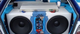
And after that we can start assembling all this in the case. So, to begin with, it is better to mark and drill holes for mounting boards, transformers, radiators for cooling microcircuits, and inputs and outputs. By the way, if you bought a rectangular switch for your amplifier, there is a small hint on how to easily make a hole on the panel for it. To begin, mark the dimensions of your future hole directly on the panel, and use a thin drill to drill a neat hole inside the perimeter of this very hole. And now the most interesting thing: take a very ordinary cotton thread (preferably thicker, thin ones often break in the process), thread it through the hole and, by pulling the thread, you can cut out any shape like a jigsaw blade. It’s just that you cut it out with a jigsaw, but here it’s like “melting it.” That is why it is better to cut a slightly smaller hole, so that you can then use a file to make it even. It is also advisable to make ventilation holes near the radiators. I played it safe and installed an additional cooler, which turned out to be useless; the amplifier does not heat up much even at maximum volume. I turn it on only when the amplifier is running outside in the summer.
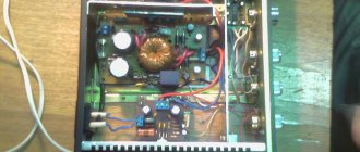
My layout looks like this (and although there are a lot of wires and it’s not pretty at all, everything has been working like a charm for six months now with regular use):
The leftmost board is a rectifier, the other 2 are amplifiers.
That's all, you can start assembling and soldering. I soldered directly into the case, without any clamps, plugs, etc. Perhaps someone will want to make everything more convenient.
Connection diagram for the volume control (two resistors are one double):
Basic recommendations:
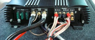
- It is better to make outputs from amplifiers with as thick a cable as possible.
- If after assembly and soldering you hear a distinct noise in the speakers, check the capacitors on the amplifier boards
- If there is a crackling sound in the speakers, then check the power traces on the amplifiers - I didn’t wash off the acidic flux well, and if you look closely in the dark, small sparks were visible between the tracks, as soon as I washed the board from the flux, the cracking disappeared.
In the end it looks like this:
Expenses:
- All capacitors and resistors in total – $4
- Chips TDA2050 (3 pcs) – $2
- Housing – $3
- All plugs, sockets, handles, switches – $7-8
Total $17 and a lot of positive emotions “It works!”
Archive with all diagrams and drawings of boards in Sprint-Layout 6 format: dl.dropbox.com/u/47591852/usilitjel_habr.rar
PS This is my first working device, assembled to test its performance and reliability. In the near future I plan to rework it in a new body and in a more accurate design. If you are interested, there will be a continuation.
Chip TDA2030A (K174UN19).
The TDA2030A is a powerful operational amplifier with a low THD Total Harmonic Distortion of less than 0.08%.
The chip has built-in thermal protection, which is triggered at a chip temperature of 150ºC, and short-circuit protection, which can protect the chip for 10 seconds when overloaded.
The microcircuit can be powered from a bipolar power source, which does not create additional difficulties with supply voltage ripple and clicks when turned on.
The Soviet analogue of this chip is K174UN19.
Limit operating data.
Supply voltage – ±6… ±22 V*,
Maximum input voltage – ±15 V,
Maximum output current – 3.5 A,
Maximum crystal temperature – 150ºС,
The maximum power dissipated by the microcircuit at case temperature ≤ 90ºС is 20 W.
——————————
* The maximum permissible voltage for K174UN19 is ±6… ±18 V
Some tips for choosing a cooling radiator.
Calculating a passive cooling radiator involves complex calculations and measurements. The results depend on many variables, and the values of some of them may be unknown to the radio amateur.
However, there are a few simple rules that can ensure reliable cooling of any electronic equipment components.
- It is necessary to ensure good contact of the semiconductor element with the radiator. To do this, it is advisable to well level the contacting surface of the radiator and use heat-conducting paste KPT-8 or any other. When there is nothing suitable, you can use silicone lubricant.
- When using insulating gaskets between the microcircuit and the heatsink, the use of thermal conductive paste is mandatory.
- It is best to choose black radiators with a matte surface.
- Reducing the temperature by 10ºС doubles the life of the microcircuit.
- You should not raise the temperature of the radiator above 60... 65ºС, and the temperature of the microcircuit case above 80... 85ºС.
Approximately, the required radiator area can be determined using a calculator by downloading the latest from the “Additional Materials” for this article. For this ULF, the required radiator area is 310 cm² or more.
Printed circuit board.
The Printed Circuit Board (PCB) is designed based on the existing radio elements and housing.
It would be more rational to place the power supply and final amplifiers on one printed circuit board, but the design of the case did not allow this, namely the fact that the power transformer occupied most of the case.
To increase the cross-section of the tracks and reduce the consumption of ferric chloride, the area of the tracks was increased using the Polygon tool.
The picture shows a fragment of a printed circuit board made of fiberglass with a cross-section of 1 mm, using the technology described here.
To increase reliability and maintainability, copper hollow rivets (pistons) pos. 1 are flared in the holes intended for installing fusible inserts.
To connect to other amplifier blocks, copper pins pos. 2 are riveted into the corresponding holes on the board.
| This movie requires Flash Player 9 |
The interactive picture shows how this printed circuit board was assembled. I added this video because, just during assembly, I was experimenting with time-lapse photography. To “manage” an image, drag the image with the mouse.
As fuses, I used sections of individual strands of MGTF wire (fluoroplastic insulated wire) with a diameter of 0.07 mm. Such improvised fuse links replace fuses with a rating of about 1 Ampere.
When installing the TDA2030 chip on a radiator, you need to keep in mind that the body of this chip is connected to the minus of the power supply. If two microcircuits are installed on one radiator at once, then it is necessary to provide for the installation of insulating gaskets. The latter can be made from any material that provides a gap of 0.03 ... 0.05 mm between the mating surfaces. For example, you can use gauze, bandage or canvas impregnated with KPT-8 thermal conductive paste.
It is convenient to fasten with M2.5 screws, onto which you must first put insulating washers and sections of an insulating tube (cambric).
This picture shows a cross-section of the connection between the microcircuit and the cooling radiator.
- Screw M2.5.
- Steel washer M2.5.
- Insulating washer M2.5.
- Chip housing.
- The gasket is a piece of tube (cambric).
- The gasket is cotton canvas impregnated with KPT-8 paste.
- Cooling radiator.