Don't dream, act!
In this project we will build a simple audio power amplifier using the popular
LM1875
. To make the design complete, we will equip it with a volume and tone control, as well as a speaker protection device. Let's get acquainted with the presented materials, assemble the basic components and enjoy the sound of our own amplifier... After some time, we will conduct a series of experiments to improve the sound produced by the amplifier.
In the first part of the project, without further ado, we will assemble Peter Smith’s “student” amplifier.
↑ A little history
In Fig. Figure 1 shows a schematic diagram of an amplifier, which at one time every enthusiastic radio engineering student assembled. At the anniversary (30 years from the date of graduation) meeting of graduates of the Novgorod Polytechnic Institute in May 2009, we discussed this amplifier, and mainly dances, in scoring and in which he took a direct part.
Rice. 1. Schematic diagram of a high-quality audio amplifier by S. Batya and V. Sereda [1] The parameters of the power amplifier are as follows:
Rated output power (Rn = 4 Ohm, Kg = 0.7%), W = 20 Operating frequency range with uneven frequency response ±0.5 dB, Hz = 20…20000 Sensitivity at rated output power and input impedance 10 kOhm, V = 1 Relative noise level, dB = -86
The amplifier is made according to the Lean topology, which has become classic, and consists of a differential input stage on transistors VT1, VT2, a voltage amplifier VT3 and a push-pull output stage VT4 - VT9. A non-inverting switching circuit has been selected. Resistor R1 determines the input resistance, and resistors R6 and R7 form a negative feedback circuit divider that sets the AC gain: Ku=1+R7/R6=11 (20.83dB).
For direct current, the transfer coefficient is equal to unity; the audio amplifier does not require amplification of direct voltage. But there are authors, say E.S. Aleshin, who argue that the amplifier must have a lower limit of amplified frequencies from direct current (0 Hz). To separate the DC and AC transmission circuits, a capacitor C3 is installed. The input circuit R1, C1 and the feedback circuit R6, C3 form high-pass filters. Since the cutoff frequencies of these filters are close, together they determine the lower limit of the frequency range reproduced by the amplifier. In our case:
The optimal resulting cutoff frequency will be a frequency an order of magnitude lower than that audible by humans, namely 1…3 Hz. In the collector circuit of the voltage amplifier VT3 there is a “voltage boost” circuit R10, R11, C5, which creates positive feedback at lower frequencies and makes it possible to improve the shape of the negative half-wave of the amplified signal. The collector VT3 also includes capacitor C4, which forms the required amplitude-frequency response at high frequencies. Typically, such a capacitor is connected between the base and collector of the voltage amplifier stage. Due to the Miller effect, its capacity turns out to be small - several tens of picofarads. The inclusion of capacitor C4 between the collector and the common wire required an order of magnitude increase in its capacity.
The output stage is made on a composite emitter follower - a triple, and the Szyklai circuit is used in the negative arm, allowing the use of powerful transistors of the same structure. Since at that time there was a shortage of everything, we bought transistors at the Avtovo radio market in Leningrad (now St. Petersburg). I remember the first time I bought transistors from a kind young man in a jacket and tie. Upon arrival in Novgorod, it turned out that all the transistors had a breakdown between the collector and the emitter, although they were not soldered. The next time I was not able to look into the eyes of this swindler, but the experience came quickly. At the radio market, I noticed a man whose hands were shaking, and his appearance was not as fashionable as the previous one. But all the transistors purchased turned out to be simply wonderful, and even with military approval!
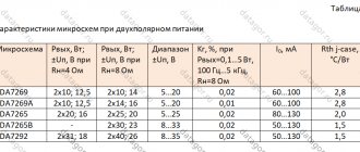
Integrated circuits 1468 (Teledyne), 3571, 3572, 3573 (BurrBrown), 8510, 8515, 8520, 8530 (Intersil), OPA502, OPA511, OPA512 (Burr-Brown), PA01, PA07, PA07A, PA10, PA10A, PA12, PA12A, PA73 (Apex) with identical circuits and different parameters are made in TO-3 packages with 8 pins. They are powerful operational amplifiers and are intended, in particular, for use as low-frequency power amplifiers in high-end sound-reproducing equipment with bipolar power supply. Some of the main parameters of the microcircuits are as follows:
| Uccmin | Uccmax | Icc0 | ΔF | Rout | Pout | Kg | Ku, for example. | |
| 1468 | ±10V | ±45V | 25mA | 20Hz-20KHz | 4Ω | 120W | 0,08% | 110dB |
| 3571 | ±10V | ±40V | 21mA | 20Hz-20KHz | 4Ω | 50W | 0,06% | 92dB |
| 3572 | ±10V | ±45V | 21mA | 20Hz-20KHz | 4Ω | 60W | 0,08% | 88dB |
| 3573 | ±10V | ±50V | 25mA | 20Hz-20KHz | 4Ω | 60W | 0,08% | 88dB |
| 8510 | ±10V | ±25V | 20mA | 20Hz-20KHz | 4Ω | 50W | 0,08% | 113dB |
| 8515 | ±10V | ±30V | 20mA | 20Hz-20KHz | 4Ω | 50W | 0,08% | 113dB |
| 8520 | ±12V | ±50V | 18mA | 20Hz-20KHz | 4Ω | 60W | 0,08% | 98dB |
| 8530 | ±12V | ±50V | 18mA | 20Hz-20KHz | 4Ω | 60W | 0,08% | 98dB |
| ORA502 | ±10V | ±45V | 40mA | 20Hz-20KHz | 4Ω | 60W | 0,08% | 103dB |
| ORA511 | ±10V | ±45V | 30mA | 20Hz-20KHz | 4Ω | 60W | 0,06% | 102dB |
| OPA512 | ±10V | ±45V | 25mA | 20Hz-20KHz | 4Ω | 50W | 0,06% | 110dB |
| PA01 | ±10V | ±28V | 20mA | 20Hz-20KHz | 4Ω | 50W | 0,05% | 113dB |
| PA07 | ±12V | ±50V | 18mA | 20Hz-20KHz | 4Ω | 60W | 0,06% | 98dB |
| PA07A | ±12V | ±50V | 18mA | 20Hz-20KHz | 4Ω | 60W | 0,06% | 98dB |
| PA10 | ±10V | ±45V | 15inA | 20Hz-20KHz | 4Ω | 60W | 0,05% | 110dB |
| RA10A | ±10V | ±50V | 15mA | 20Hz-20KHz | 4Ω | 60W | 0,05% | 110dB |
| RA12 | ±10V | ±45V | 25mA | 20Hz-20KHz | 4Ω | 120W | 0,8% | 110dB |
| PA12A | ±10V | ±50V | 25mA | 20Hz-20KHz | 4Ω | 120W | 0,8% | 110dB |
| PA73 | ±10V | ±30V | 20mA | 20Hz-20KHz | 4Ω | 50W | 0,8% | 113dB |
Microcircuits OPA502, OPA511 and OPA512 are available in two modifications (with the suffixes VM and SM, for example OPA502VM and OPA502SM), which have identical parameters and differ in temperature range (-40°C-+85°C for VM and -55°C-+ 125°C for SM). The microcircuits have built-in output protection against short circuits in the load, against increased supply voltage and thermal protection (150°C). To obtain maximum output power, the microcircuit must be installed on an appropriate heat sink (radiator).
A1034, AN7108, CXA1005P, CXA1034P, KA22132
Integrated circuits A1034 (NEC), AN7108 (Matsushita), SХА1005Р and СХА1034Р (Sony), KA22132 (Samsung) with identical circuits and parameters are made in DIP packages with 16 pins. They are two-channel playback amplifiers, tone correctors and low-frequency power amplifiers. Designed for use in small-sized high-class cassette recorders (players). Frequency correction circuits are provided when reproducing the frequency response in accordance with the NAB standard for FeO magnetic tape. The microcircuits allow electronic volume control via a variable resistor VOLUME. The main parameters of the microcircuits (output parameters for one channel) are as follows:
| Uccmin | Uccmax | Icc0 | ΔF | Rout | Pout | Kg | Ku, for example. |
| 1.5 V | 6 V | 2 mA | 15Hz-20KHz | 32Ω | (4.5V/32Ω) 0.1W | 0,01% | 68dB |
The microcircuits have built-in output protection against short circuits in the load and against increased supply voltage. To obtain maximum power output, there is no need for a heat sink (heatsink).
A2000V, A2005V, DBL1032-D, LM2005, TDA2004A, TDA2005S, TDA2005M,
μ PC2005
Integrated circuits A2000V and A2005V (RFT), DBL1032-D (GoldStar), LM2005 (National Semiconductor), TDA2004A, TDA2005S, TDA2005M (SGS-Thomson), μPC2005 (NEC) with identical circuits and different parameters are made in SIP1 packages with 11 pins . They are two-channel (stereophonic) low-frequency power amplifiers and are intended for use in tape recorders (including automobile ones), electrophones, and other middle- and high-class audio equipment. It is also possible to connect microcircuits without using positive feedback, which allows you to use a smaller number of attachments. To obtain double the output power at the same load resistance, with the same supply voltage, the microcircuits can be connected via a bridge circuit. The TDA2005M chip is designed specifically for use in a bridge circuit. Some of the main parameters of the microcircuits (output parameters - for one channel; for TDA2005M - in a bridge circuit) are as follows:
| Uccmin | Uccmax | Icc0 | ΔF | Rout | Pout | Kg | Ku, for example. | |
| A2000V | 4V | 18V | 30mA | 40Hz-20KHz | 2Ω | 6.25W | 0,25% | 84dB |
| A2005V | 4V | 18V | 75mA | 40Hz-20KHz | 2Ω | 6.5W | 0,22% | 85dB |
| DBL1032-D | 8V | 18V | 65mA | 35Hz-20KHz | 2Ω | 10W | 0,2% | 90dB |
| LM2005 | 8V | 18V | 65mA | 35Hz-20KHz | 2Ω | 10W | 0,2% | 90dB |
| TDA2004A | 8V | 18V | 65mA | 35Hz-20KHz | 2Ω | 10W | 0,2% | 90dB |
| TDA2005S | 8V | 18V | 65mA | 40Hz-20KHz | 2Ω | 10W | 0,2% | 90dB |
| TDA2005M | 8V | 18V | 75mA | 35Hz-20KHz | 3.2Ω | 22W | 1% | 50dB |
| μRS2005 | 8V | 18V | 65mA | 40Hz-20KHz | 2Ω | 9.5W | 0,2% | 90dB |
The microcircuits have built-in output protection against short circuits in the load, against increased supply voltage and thermal protection (145 C). To obtain maximum output power, the microcircuits must be installed on a heat sink (radiator)
A2030H, A2030V, K174 U H19, L165, LM1875, 0PA544, TDA2006H, TDA2006V, TDA2030H, TDA2030V, TDA2030AH, TDA2030AV, TDA2040H, TDA2040V. T D A 2050 N ,
T D A 2050V, T D A 2051 N , T D A 2051V, μRS 1238
Integral chips A2030N and A2030V (RFT), K174UN19 (CIS), LM1875 (National Semiconductor), L165, TDA2006H, TDA2006V, TDA2006V, TDA2006V, TDA2006V, TDA2006V, TDA2006V, TDA2006V, TDA2006V, TDA2006V, TDA2006V, TDA2006V, TDA2006V, TDA2006V, TDA2006V, TDA2006V, TDA2006V, TDA2006V, TDA2006V, TDA2006V, TDA2006V, TDA2006V, TDA2006V, TDA200V TDA2030H, TDA2030V, TDA2030AH, TDA2030AV, TDA2040H, TDA2040V, TDA2050H, TDA2050V, TDA2051H and TDA2051V (SGS-Thomson OPA544 (Burr-Brown), (μPC1238 (NEC) with identical circuits and different parameters are made in TO-220 housings with 5 pins formed in two rows, parallel to the plane of the case. For microcircuits with the suffix V, the leads are bent perpendicular to the plane of the case.
They are low-frequency power amplifiers and are intended for use in tape recorders, electrophones, and other mid- and high-class audio equipment with bipolar power supply. Diodes D1 and D2 protect the output transistors of the microcircuits from reverse voltage surges induced by the idle reverse of the loudspeaker coil. It is also possible to connect microcircuits in a single-supply circuit. To obtain double the output power at the same load resistance, with the same supply voltage, the microcircuits can be connected via a bridge circuit. Some of the main parameters of the microcircuits are as follows:
| Ucmin | Uccmax | Icc0 | ΔF | Rout | Pout | Kg | Ku | |
| A2030N | ±6V | ±18V | 60mA | 30Hz-20KHz | 4Ω | 16W | 0,1% | 84dB |
| A2030V | ±6V | ±18V | 60mA | 30Hz-20KHz | 4Ω | 16W | 0,25% | 84dB |
| K174UN19 | ±6V | +18V | 56mA | 30Hz-20KHz | 4Ω | 15W | 0,1% | 84dB |
| L165 | ±6V | ±18V | 60mA | 30Hz-20KHz | 4Ω | 12W | 0,1% | 80dB |
| LM1875 | ±6V | ±18V | 60mA | 30Hz-20KHz | 4Ω | 16W | 0,1% | 84dB |
| ORA544 | ±10V | +35V | 24mA | 20Hz-140KHz | 4Ω | 30W | 0,05% | 90dB |
| TDA2006H | ±6V | ±15V | 40mA | 20Hz-20KHz | 4Ω | 12W | 0,2% | 75dB |
| TDA2006V | ±6V | ±15V | 40mA | 20Hz-20KHz | 4Ω | 12W | 0,2% | 75dB |
| TDA2030H | ±6V | ±18V | 40mA | 10Hz-20KHz | 4Ω | 18W | 0,2% | 90dB |
| TDA2030V | ±6V | ±18V | 40mA | 10Hz-20KHz | 4Ω | 18W | 0,2% | 90dB |
| TDA2030AH | ±6V | ±22V | 50mA- | 40Hz-20KHz | 4Ω | 18W | 0,2% | 80dB |
| TDA2030AV | ±6V | ±22V | 50mA | 40Hz-20KHz | 4Ω | 18W | 0,2% | 80dB |
| TDA2040H | ±2.5V | ±20V | 45mA | 40Hz-20KHz | 4Ω | 2ZW | 0,5% | 80dB |
| TDA2040V | ±2.5V | ±20V | 45mA | 40Hz-20KHz | 4Ω | 22W | 0,5% | 80dB |
| TDA2050H | ±2.5V | ±25V | 55mA | 40Hz-20KHz | 4Ω | 35W | 0,5% | 80dB |
| TDA2050V | ±2.5V | ±25V | 55mA | 40Hz-20KHz | 4Ω | 35W | 0,5% | 80dB |
| TDA2050H | ±2.5V | ±25V | 55mA | 40Hz-20KHz | 4Ω | 40W | 0,5% | 80dB |
| TDA2050V | ±2.5V | ±25V | 55mA | 40Hz-20KHz | 4Ω | 40W | 0,5% | 80dB |
| μRS1238 | ±6V | ±28V | 60mA | 30Hz-20KHz | 4Ω | 16W | 0,1% | 84dB |
The microcircuits have built-in output protection against short circuits in the load and thermal protection (150°C). To obtain maximum output power, the microcircuit must be installed on a heat sink (radiator).
AN272
The AN272 integrated circuit from Matsushita is housed in a SIP2 package with 10 pins and is a low-frequency power amplifier. Designed for use in tape recorders, electrophones, television and radio receivers, and other middle-class audio equipment with bipolar power supply. Some of the main parameters of the microcircuit are as follows: Uccmin ±8 V Uccmax ±17 V Pout(±10V/8n) 5 W Icc0(Uin=0) 20 mA Rin 180KΩ Ku, e.g. 80dB ΔF 40Hz-18KHz Kg(Pout=0.5W,f=1KHz) 0.13% Routnom 8Ω The microcircuit has built-in output protection against short circuit in the load. To obtain maximum output power, the microcircuit must be installed on a heat sink (radiator).
AN274, AN374, AN374P
Integrated circuits AN274, AN374 and AN374P from Matsushita are made in TO-100 packages with 10 pins (AN274 and AN374) and SIL with 7 pins (AN374P). They are low-frequency power amplifiers and are intended for use in tape recorders, electrophones, televisions and radios, and other low-class audio equipment. The AN374 and AN374P microcircuits are identical in parameters and differ in pinout. A typical connection diagram (for AN274 and AN374) is shown in Figure 1, for AN374 - in Figure 2.
Some of the main parameters of the microcircuits are as follows:
| AN274 | AN374 | |
| Uccmin | 6V | 6V |
| Uccmax | 16 V | 16 V |
| Pout(10V/8Ω) | 1.3 W | 1 W |
| Icc0(Uin=0) | 8 mA | 8 mA |
| Rin | 150KΩ | 150KΩ |
| Ku, for example. | 72dB | 72dB |
| ΔF | 50Hz-17KHz | 50Hz-17KHz |
| Kg(Pout=0,lW,f=lKHz) | 0,1% | 0,15% |
| Routnom | 8Ω | 8Ω |
The microcircuits do not have output protection against short circuits in the load. To obtain maximum output power, the microcircuit does not need to be installed on a heat sink (radiator).
AN313
The AN313 integrated circuit from Matsushita is housed in a TABS6 package with 16 pins and is a two-channel (stereo) low-frequency power amplifier. Designed for use in tape recorders, electrophones, television and radio receivers, and other middle-class audio equipment. Some of the main parameters of the microcircuit (output parameters for one channel) are as follows: Uccmin 12 V Uccmax 20 V Pout(16V/8Ω) 3 W Icc0(Uin=0) 40 mA Rin. 150KΩ Ku, e.g. 76dB ΔF 40Hz-18KHz Kg(Pout=0.2W, f=lKHz) 0.15% Routnom 8Ω
The microcircuit has built-in output protection against short circuit in the load. To obtain maximum output power, the microcircuit must be installed on a heat sink (radiator).
AN315
The AN315 integrated circuit from Matsushita is housed in a SIP2 package with ll pins and is a low-frequency power amplifier. Designed for use in tape recorders, electrophones, television and radio receivers, and other middle-class audio equipment. Some of the main parameters of the microcircuit are as follows: Uccmin 9 V Uccmax 18 V Pout(13V/4Ω) 5.5 W Icc0(Uin=0) 28 mA Rin 120KΩ Ku, for example. 76dB ΔF 40Hz-18KHz Kg(Pout==0.5W, f=lKHz) 0.1% Routnom 4Ω
The microcircuit has built-in output protection against short circuit in the load. To obtain maximum output power, the microcircuit must be installed on a heat sink (radiator).
AN7102S
The AN7102S integrated circuit (Matsushita) is housed in a 16-pin DIP package and is a two-channel playback amplifier, tone equalizer, and low-frequency power amplifier. Designed for use in small-sized high-class cassette recorders (players). Frequency correction circuits are provided when reproducing the frequency response in accordance with the NAB standard for FeO magnetic tape. The main parameters of the microcircuit (output parameters for one channel) are as follows: Uccmin 1.5 V Uccmax 4.5 V Pout(3V/32Ω) 75 mW Icc0(Uin=0) 2 mA Ku, e.g. 68dB ΔF 15Hz-20KHz Uinmax 10 mV Kg(Pout=1mW, f=1KHz) 0.01% Uin0 14mV Routnom 32Ω
The microcircuit has built-in output protection against short circuits in the load and against increased supply voltage. To obtain maximum power output, there is no need for a heat sink (heatsink).
AN7106K
The AN7106K (Matsushita) IC is housed in a 24-pin DIP package and is a two-channel playback amplifier, tone equalizer, and low-frequency power amplifier. Designed for use in small-sized high-class cassette recorders (players). Frequency correction circuits are provided when reproducing the frequency response in accordance with the NAB standard for FeO magnetic tape. The main parameters of the microcircuit (output parameters for one channel) are as follows: Uccmin 1.5 V Uccmax 4.5 V Pout(3V/32Ω) 140 mW Icc0(Uin=0) 6 mA Ku, e.g. 62dB ΔF 15Hz-20KHz Uinmax 10 mV Kg(Pout=10mW, f=1KHz) 0.01% Uin0 10mV Routnom 32Ω
The microcircuit has built-in output protection against short circuits in the load and against increased supply voltage. To obtain maximum power output, there is no need for a heat sink (heatsink).
AN7112, KA2212, LA4140, TA7313AR
Integrated circuits AN7112 (Matsushita), KA2212 (Samsung), LA4140 (Sanyo) and TA7313AP (Toshiba) with identical circuits and parameters are made in SIL packages with 9 pins. They are low-frequency power amplifiers and are intended for use in cassette recorders, television and radio receivers, and other low-class audio equipment. The main parameters of the microcircuits are as follows: Uccmin 4 V Uccmax 14 V Pout(9V/l6Ω) 0.5 W Icc0(Uin=0) 12 mA Ku, e.g. 62dB ΔF 40Hz-18KHz Kg(Pout=20mW, f=lKHz) 0.1% Routnom 8Ω
The microcircuits have built-in output protection against short circuits in the load. To obtain maximum power output, there is no need for a heat sink.
AN7116
The AN7116 integrated circuit from Matsushita is housed in a 9-pin SIL package and is a low-frequency power amplifier. Designed for use in tape recorders, electrophones, television and radio receivers, and other low-class audio equipment. Some of the main parameters of the microcircuit are as follows: Uccmin 3 V Uccmax 9 V Pout(6V/4Ω) 0.77 W Icc0(Uin=0) 13 mA Rin 100KΩ Ku, for example. 42dB ΔF 40Hz-17KHz Kg(Pout=0.lW, f=lKHz) 0.2% Routnom 4Ω
The microcircuit has built-in output protection against short circuit in the load. To obtain maximum power output, there is no need for a heat sink (heatsink).
AN7117
The AN7117 integrated circuit from Matsushita is housed in a 9-pin SIL package and is a low-frequency power amplifier. Designed for use in tape recorders, electrophones, television and radio receivers, and other low-class audio equipment. Some of the main parameters of the microcircuit are as follows: Uccmin 3 V Uccmax 9 V Pout(9V/4Ω) 0.66 W Icc0(Uin=0) 8 mA Rout 150KΩ Ku, for example. 66dB ΔF 40Hz-17KHz Kg(Pout=0.lW, f=lKHz) 0.15% Routnom 4Ω
The microcircuit has built-in output protection against short circuit in the load. To obtain maximum power output, there is no need for a heat sink (heatsink).
AN7118, AN7118S
Integrated circuits AN7118 and AN7118S from Matsushita are made in DIP packages with 16 pins (AN7118) and mini-DIP with 18 pins (AN7118S) and are two-channel (stereo) low-frequency power amplifiers with identical parameters and circuits, but different pinouts. Designed for use in low-end battery-powered cassette recorders. A typical connection diagram for AN7118 is shown in Fig. 1, for AN7118S in Fig. 2. Some of the main parameters of the microcircuits (output parameters for one channel) are as follows: Uccmin 1.5 V Uccmax 4.5 V Pout(3V/4Ω) 0 ,13 W Icc0(Uin=0) 8 mA Routn 120KΩ Ku, e.g. 66dB ΔF 30Hz-18KHz Kg(Pout=0.01W, f=lKHz) 0.2% Routnom 4Ω
The microcircuits have built-in output protection against short circuits in the load. To obtain maximum power output, there is no need for a heat sink (heatsink).
AN7120
The AN7120 integrated circuit from Matsushita is housed in a TABS5 package with 14 pins and is a low-frequency power amplifier. Designed for use in tape recorders, electrophones, television and radio receivers, and other middle-class audio equipment. Some of the main parameters of the microcircuit are as follows: Uccmin 6 V Uccmax 18 VPout(9V/4Ω) 2.1 W Icc0(Uin=0) 27 mA Rin 150KΩ Ku, for example. 66dB ΔF 40Hz-18KHz Kg(Pout=0.5W, f=lKHz) 0.5% Routnom 4Ω
The microcircuit has built-in output protection against short circuit in the load. To obtain maximum output power, the microcircuit must be installed on a heat sink (radiator).
AN7133
The AN7133 integrated circuit from Matsushita is made in an SDIP package with 24 pins and is a two-channel (stereo) low-frequency power amplifier. Designed for use in tape recorders, electrophones, television and radio receivers, and other middle-class audio equipment. The microcircuit has built-in output protection against short circuit in the load. To obtain maximum output power, the microcircuit must be installed on a heat sink (radiator). Some of the main parameters of the microcircuit (output parameters for one channel) are as follows: Uccmin 10 V Uccmax 20 V Poutmax 2.1 W Icc0(Uin=0) 22 mARoutn 120KΩ Ku, for example. 68dB ΔF 30Hz-18KHz Kg(Pout=0.2W, f=lKHz) 0.15% Routnom 4Ω
AN7139, AN7143, AN7147, AN7148, AN7149N, AN7168, AN7169, AN7176, AN7178, HA1377, HA1377A, HA1398, HA13108, K1075 U H1, M5160L, M51601L
Integrated circuits AN7139,AN7143,AN7147,AN7148,AN7149N,AN7168, AN7169,AN7176,AN7178 (Matsushita),HA1377,HA1377A,HA1398,HA13108 (Hitachi), K1075UN1 (CIS), M5160L and M51601 L (Mitsubhishi) are made in SIP1 housings with 12 pins and are two-channel (stereophonic) low-frequency power amplifiers with identical circuits (pinouts) and different parameters. Designed for use in tape recorders, electrophones, television and radio receivers, and other mid- and high-class audio equipment. Some of the main parameters of the microcircuits (output parameters for one channel) are as follows:
| Uccmin | Uccmax | Icc0 | ΔF | Rout | Pout | Kg | Ku, for example. | |
| AN7139 | 9V | 24V | 30mA | 40Hz-20KHz | 4Ω | 3.5W | 0,2% | 62dB |
| AN7143 | 4.3V | 24V | 30mA | 40Hz-20KHz | 4Ω | 2W | 0,2% | 62dB |
| AN7147 | 8V | 24V | ZOTA | 40Hz-20KHz | ZΩ | 5.8W | 0,2% | 62dB |
| AN7148 | 9V | 24V | 30mA | 40Hz-20KHz | 4Ω | 3.5W | 0,2% | 62dB |
| AN7149N | 9V | 24V | 30mA | 40Hz-20KHz | 4Ω | 3.5W | 0,2% | 62dB |
| AN7168 | 8V | 24V | 30mA | 40Hz-20KHz | 4Ω | 5.7W | 0,2% | 62dB |
| AN7169 | 12V | 24V | 30mA | 40Hz-20KHz | 4Ω | 5.8W | 0,2% | 62dB |
| AN7176 | 12V | 24V | 30mA | 40Hz-20KHz | 4Ω | 7.5W | 0,2% | 62dB |
| AN7178 | 9V | 24V | 30mA | 40Hz-20KHz | 4Ω | 2.8W | 0,2% | 62dB |
| NA1377 | 8V | 18V | 30mA | 40Hz-20KHz | 4Ω | 5.8W | 0,2% | 62dB |
| NA1377A | 8V | 18V | 30mA | 40Hz-20KHz | 4Ω | 7W | 0,2% | 62dB |
| NA1398 | 8V | 18V | 30mA | 40Hz-20KHz | 4Ω | 5.8W | 0,2% | 62dB |
| NA13108 | 9V | 18V | 30mA | 40Hz-20KHz | 4Ω | 5.5W | 0,2% | 62dB |
| K1075UN1 | 9V | 18V | 50mA | 40Hz-20KHz | 4Ω | 3.5W | 0,23% | 42dB |
| M5160L | 12V | 30V | 40mA | 30Hz-20KHz | 4Ω | 7.5W | 0,2% | 62dB |
| M51601L | 5V | 18V | 25mA | 30Hz-20KHz | 4Ω | 4.5W | 0,2% | 62dB |
The microcircuits have built-in output protection against short circuits in the load, against increased supply voltage and thermal protection. To obtain maximum output power, the microcircuit must be installed on a heat sink (radiator).
To main
| Popular science educational resource |
↑ Disadvantages of the scheme and ways to improve it
The main disadvantages of the classically designed Lin circuit are the insufficient gain without negative feedback, with the bandwidth and slew rate of the output voltage leaving much to be desired.
Although harmonic distortion at 1 kHz does not exceed one percent, above 1 kHz the distortion increases fourfold for every octave increase in signal frequency. Intermodulation distortion turns out to be three times higher than nonlinear distortion, so this circuit demonstrates only the very initial level of high-quality sound, requiring improvements. Subsequently, this typical UMZCH circuit was subjected to many improvements affecting all components: differential stage, voltage amplifier and output stage. A significant improvement in the characteristics of the differential cascade can be achieved by replacing the resistive quasi-current generator (R4) with a transistor one. Stability, performance, gain, suppression of common mode signals and interference in power circuits are increased by approximately an order of magnitude. The next step to improve the linearity and dynamic characteristics of the input differential stage is to use current reflectors and current mirrors in the collector load (instead of resistors R2, R3). Essentially, the current mirror balances two unbalanced current paths, providing significant improvements in linearity and increasing common mode rejection as well as ripple rejection.
Replacing the resistive load (R10, R11) in the VT3 voltage amplification stage with a transistor stable current generator gives the same order of performance improvement as in the differential stage. To increase the DC gain, a circuit technique is used - a buffer emitter follower; to increase the frequency of the main pole - a cascode circuit. Increasing the depth of overall feedback in the audio frequency range without increasing the cutoff frequency of the entire amplifier is achieved by bipolar correction in the voltage amplification stage. The output stage (Fig. 1) operates in class AB and is made of triplets of transistors according to a quasi-complementary circuit. The use of three transistors instead of the desired two is caused primarily by the low values of the transistor transmission coefficients with a low load resistance (speaker system, Rn = 4 Ohms).
Improvements in the operation of the output stage are achieved by using an element base specially designed for sound reproduction purposes:
- complementary transistors (for example,
2SC3281/2SA1302
from Toshiba), high-power complementary multi-emitter transistors (abbreviation LAPT,
2SC3284/2SA1303
from Sanken);
— powerful bipolar transistors with insulated gate (IGBT, for example, GT20D201/GT20D101
from Toshiba);
— field-effect transistors ( 2SK1058/2SJ162
) and other semiconductor devices.
An important improvement can be considered the release of integrated circuits for audio power amplifiers, which significantly simplified the application with characteristics comparable to those of devices using discrete components. As an example in Fig. Figure 2 shows a simplified circuit of the TDA2050
STMicroelectronics
company [2].
Power amplifiers TDA2006, TDA2030, TDA2040
and others have a similar circuit [3-7].
Rice. 2. Functional diagram of the integrated audio power amplifier TDA2050
To increase the input resistance, the differential stage (DC) is made on composite emitter followers VT4, VT5 and VT9, VT10. The optimal choice of DC operating mode and the use of pnp transistors, which have a lower volumetric base resistance compared to transistors of the opposite structure, made it possible to obtain an insignificant noise level (the typical noise voltage referred to the input in the frequency range from 22 Hz to 22 kHz is no more 5 µV).
A current mirror VT7, VT8 is installed in the collector load of the DC, and a current source VT6 is included in the emitter circuit. The voltage amplification stage is also made using a composite circuit using transistors VT11, VT13, which made it possible to obtain a high gain without feedback, more than 80 dB. Capacitor C2 performs single-pole frequency correction. To increase the phase margin, the voltage amplification stage and the output stage are covered by another frequency correction circuit through capacitor C1 (the so-called inclusive frequency correction).
The output stage of the microcircuit (VT18, VT20 and VT15, VT16, VT21) is made according to a quasi-complementary circuit, characteristic of amplifier technology of the seventies of the last century. Inclusive frequency correction helps to equalize the phase characteristics of the asymmetrical arms of the output stage, resulting in an acceptable balance between the manufacturability of the microcircuit (read: price) and the implemented fairly high technical characteristics.
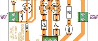
↑ Integrated circuits TDA2006, TDA2030, TDA2040, TDA2050, LM1875
All the microcircuits indicated in the title are located in a convenient TO220 case, which has five pins and a hole for attaching to a radiator. The connection diagram for external elements is shown in Fig. 3, in table. 1 shows the values of the elements and technical characteristics of the UMZCH.
Rice. 3. Basic circuit for connecting single-channel integrated circuits of audio power amplifiers
Table 1: