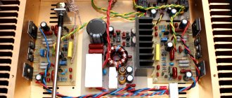
Hello, friends! I apologize in advance for the quality of the illustrations. So it all started with an attempt to create a UPS. The first option was assembled according to the minimum parts scheme. Here is a link to the article: Simple pulse power supply for UMZCH. I would like to warn you in advance that all efforts belong not to me, but to my friend and colleague Sergei. I just didn’t have enough experience, but I honestly helped as much as I could. In parallel with assembling the power supply, the housing from the “START” amplifier, which I had bought for small change, was brought into production. The idea practically grew into an amplifier with a UPS. Continuing to collect food, we made the food itself, and for some reason it was ready earlier than the food. Joy knew no bounds. I was in nirvana. I was driven by interest. But, as they say, you want a lot at once, but you get nothing gradually. Here's what we got:
The article discusses the implementation of a two-channel amplifier on the TDA2050, connected according to a voltage-controlled current source (VCS) circuit. This circuit, created by Lincor, has been known for a long time and has been attracting fans to experiment with sound for a long time. The original article will be at the end of the material.
The TDA2050 is a more powerful and improved analogue of the well-known TDA2030, which was spontaneously installed in almost every budget amplifier. Despite the fact that both microcircuits have been out of production for more than 10 years, they can still be found in active computer speakers, where the Chinese solder, although high-quality, but fake TDA2050 microcircuits. Therefore, if you have several old original microcircuits on hand, then it’s time to assemble a wonderful amplifier with an interesting sound.
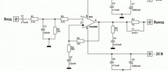
The figure below shows a diagram of the stereo version of ITUN on the TDA2050. In comparison with the original Lincora circuit, we made some modifications to obtain higher quality sound: film capacitors C7, C13 - C15 were added with a capacitance increased to 1 µF, capacitors C9 C11, included in the OOS circuit, were bypassed with high-quality “film”, and the wire capacitor was removed cement resistor SQP and replaced it with two film MF-2 connected in parallel. Such improvements (especially the shunting of C9 and C11), coupled with correct routing, resulted in a lighter and freer sound at the output, and improved high frequencies.
It is better to use metal film capacitors CL21 (domestic analogue K73-17) in the Zobel circuit C16 C17. As input coupling capacitors C1 - C4, you can also use CL21 or polystyrene type CL11 (K73-9), capacitance 330 nF - 1 µF. Capacitors C5 C6 can be any film or ceramic, but must have an NP0 (C0G) dielectric.
The PCB file in P-CAD 2006 format, as well as assembly maps in good quality, can be downloaded from the link below. The board has DJ610-6.3 (TA-M) type power terminals, and the outputs use DG127 (DG128 or XY304). The input connector is W-03 type with a pin pitch of 2.54 mm. In its place, you can mount a regular PLS-3 (known as a “comb”). Resistors RZ1 - RZ4 (not shown in the diagram) have zero resistance (jumpers, “zeros”) and size 1206. The remaining SMD components are in size 0805.
| Mariolla MRL-2050.zip (557 KB) |
You can purchase the amplifier from us. Product link - Power amplifier 2 x 35W according to ITUN Mariolla MRL-2050 scheme
Amplifier wiring diagrams (top and bottom views). The positional designations fully correspond to the diagram.
For those who are getting acquainted with the TDA2050 microcircuit for the first time, we provide a BRIEF REFERENCE .
TDA2050 is a monolithic integrated circuit in a Pentawatt package, designed for use as an audio amplifier operating in class AB. High power and very low THD and step distortion (THD = 0.05% typical, at VS = ± 22V, POUT = 0.1 ... 15 W, RLOAD = 8R) make the device most suitable for HI-FI, as well as HI-END TV equipment.
| TDA2050 Basic Electrical Specifications Table data values at test conditions Vs = ± 18V, TAMB = 25 °C, F = 1 kHz unless otherwise noted | ||
| Parameter | Test conditions | Meaning |
| Supply voltage Vs | ± 4.5 — ± 25 V | |
| Quiescent current | Vs = ± 4.5V Vs = ± 25V | 30 – 50 mA 55 – 90 mA |
| Input bias current | Vs=±22V | 0.1 - 0.5 uA |
| Offset voltage | Vs=±22V | ± 15 mV |
| Output power THD = 0.5% | RL = 4R RL = 8R Vs = ± 22V, RL — 8R | 24 - 28 W 18 W (typ) 22 - 25 W |
| Output power THD = 10% | RL = 4R RL = 8R Vs = ± 22V, RL — 8R | 35 W 22 W 32 W |
| Musical Power IEC268.3 Standard | THD = 10%, T = 1s RL = 4R; Vs = ±22.5V | 50 W |
| Distortions | Vs = ± 22V PO = 0.1 … 20W RL = 8R, F = 1 kHz | 0.02 — 0.05 % |
| Slew Rate | 5 - 8 V/us | |
| Voltage Gain (Open Loop) | F = 1 kHz | 80 dB |
| Voltage Gain (Closed Loop) | F = 1 kHz | 30 - 31 dB |
| Frequency range of operation | VIN = 200 mV RL = 4R | 20 - 80 000 Hz |
| Input noise voltage | 22 Hz - 22 kHz | 5 - 10 uV |
| Input impedance | 500 kOhm | |
| Power supply ripple suppression | RG = 22 kΩ, F = 100 Hz VRIPPLE = 0.5 VRMS | 45 dB |
| Efficiency | PO = 28W, RL = 4R PO = 25W, RL = 8R Vs = ± 22 V | 65 % 67 % |
| Shutdown temperature | Crystal temperature | 150 0C |
TDA2050 according to the ITUN scheme from Lincor (original article, highlights)
The reader is offered an easy-to-make yet highly conceptual amplifier. The basic circuit implements the ITUN principle - a voltage-controlled current source. Briefly, its essence is as follows: the Lorentz force acting on a conductor in a magnetic field (coil of a dynamic head (DG) in a magnetic system) is a function of the current flowing in the conductor (coil). However, most industrial and proprietary UMZCHs are voltage sources. And their frequency response is standardized precisely by voltage. However, the DW resistance at different frequencies is obviously significantly nonlinear. And, consequently, the current in the coil depends nonlinearly on its reactance. You can read more in the article by A. Lyubimov “Sweet couple: loudspeaker + ultrasound”.
ITUN circuit on TDA2050 from Lincor
The project of this UMZCH was the result of an analysis of the solutions proposed in the above article, a topic about current control on HiFi.ru, the collaboration of comrades from the vlab forum and a set of trim filters proposed by Skif. The author has been familiar with this IC for quite a long time and in previous articles he also noted its comfortable and balanced sound, which is subjectively superior in detail and HF passages to such branded flagships as TDA7294 and LM3886.
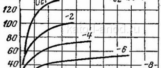
The previous article did not pay sufficient attention to the nuances of the behavior of the feedback loop in the above inclusion. The results of the circuit simulation were analyzed, tabulated, and allow us to draw certain conclusions regarding the ratings of the complex OOS circuit. The fact is that the Ku of the circuit is calculated rather ambiguously and is significantly nonlinear. On the other hand, there is such a problem as limiting the signal when the amplitude is exceeded. Normalized gain mode for standard turn-on requires an input voltage of 0.5 V for rated power. Therefore, the simulation was carried out precisely at this voltage. On the third hand, there was the problem of capacity in the environmental protection system. The offset at the output of the IC is significant, but we do not need it, so the reference voltage must be removed from the capacitor to get rid of the zero harmonic. Let's start calculating the circuit with resistor R6. Let's set its nominal value to 1 kOhm. Then the resistance of a capacitance of 100 μF at a frequency of 20 Hz will be Z = 1/(2πfC) = 80 Ohms. This is perfectly suited for our purposes, because... the complex resistance at the lower operating frequency will have an angle of no more than 50. Based on the given parameters, I carried out a series of simulations. The results are summarized in a table.
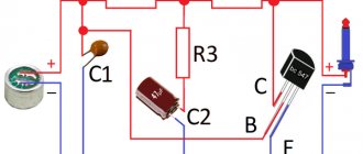
In my opinion, the optimal ratio of denominations is marked in yellow. The designation “OGR” means that the amplitude was greater than the supply voltage (± 20V) and the sinusoid went into limitation. Based on this, the circuit acquired the element values indicated in the first figure.
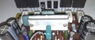
Capacitors C1 and shunt C3 are film K73-17 x 63V. C2 and C5 – K10-17B ceramics. Circuit R7 C5 is installed only if the IC is excited, which was not observed in my case. Current-setting resistor R4 is a metal wire in a ceramic housing. Of the available ratings - 0.22 Ohm, usually used in OBR output transistors. The decisive importance here is played by the same denominations and the relatively better sound of metal wires compared to carbon ones. The MS itself can be replaced with a TDA2030 or LM1875.
And, finally, about the parameters and sound. It is worth considering that the ITUN mode justifies itself when working on single-band or two-band systems with the simplest filters no higher than first order (capacitor in series with the tweeter). UMZCH provides output power of up to 20W with a minimum level of distortion and peak power of up to 50W, but this mode is uncharacteristic for the TDA2050 and is extremely extreme. Power supply up to ± 20V, higher thermal and musical modes are also undesirable.
Sound tests were carried out on a modernized 8GDSH-2-8 acoustic system, housed in a ZYa with a volume of about 17 liters. Tests showed high sound contrast, extremely high detail and elaboration of the sound stage. The amplifier emphasizes the high frequencies very melodiously. In general, the sound is similar to a tube one, but does not have its disadvantages - such as emphasized “roundness”, coloration of the sound and low dynamics. At the same time, ITUN sounds more comfortable and softer than transistor UMZCHs made using classical circuitry. It features concentrated bass and less whistling treble. Despite all the advantages, it should be noted that its assembly is justified only for working on sensitive acoustics with first-order filters. When working on speakers like S-30, etc. The behavior of the frequency response is completely unpredictable, especially in the filter section.
To summarize, I will say that this amplifier is worth assembling at least for the sake of experimentation, and owners of wideband speakers, I am sure, will be surprised by the new capabilities of their acoustics, which have long been asking for a trash can.
RELATED MATERIALS
- Power amplifier 2 x 100W Mariolla MRL-7293ST
- Amplifier 2 x 120W on STK411-240E
- Power amplifier Mariolla VS-270TD
- Power amplifier 200W based on field-effect transistors Mariolla MOSFIT-200
- Power amplifier 100W Mariolla MRL-7294
- Chip TDA7388. Part 1 - description and characteristics
- Power amplifier 2 x 35W according to ITUN Mariolla MRL-2050 circuit
- Amplifier 2 x 22 W on TA8210A
- Power amplifier 4 x 45W Mariolla MRL-7388
- Car amplifier circuits based on TDA8561Q
- Chip TDA8561Q (datasheet in Russian)
AdmirorGallery 5.2.0, author/s Vasiljevski & Kekeljevic.
Comments
+4 DFR 06/26/2019 09:29 Finally found this article.
Thanks a lot. Reply | Reply with quote | Quote
Update list of comments RSS feed of comments for this entry
Add a comment
Schematic diagram
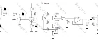
The schematic diagram is shown in the figure. The stereo audio input signal is supplied to connector X1. Next, the signal is supplied via a shielded cable to the control panel, which includes a passive volume control, stereo balance and a passive tone control for low and high frequencies.
Rice. 1. Schematic diagram of a sound amplifier based on TDA2050 microcircuits with a tone block.
Double variable resistor R1 serves as a volume control, single variable resistor R2 serves as a stereo balance control (resistors R3 and R4 prevent shorting of the inputs at the extreme positions of R2 and the maximum position of R1.
The passive tone control is made according to a standard passive circuit using dual variable resistors R7 and R9. The variable resistor R7 adjusts the timbre for low frequencies, and the variable resistor R9 adjusts the timbre for high frequencies.
From the output of the tone control, low-frequency signals are sent to amplifiers on microcircuits A1 and A2. The amplifiers are included according to standard circuits for the TDA2050 when powered from a unipolar source.
To do this, a bias voltage equal to half the supply voltage is applied to the direct input of the amplifier, which is also the main signal input. This voltage is created for each microcircuit separately, by dividers on resistors R13, R15 and R20, R21.
Each TDA2050 chip is essentially a powerful operational amplifier. And its gain depends on the OOS circuit between the output and the inverse input of the op-amp. In this case, these are chains R17, R16, C15 and R23, R22, C16, respectively.
By changing the parameters of these circuits, you can change the gain of the microcircuit within a very wide range, thus changing the sensitivity of the ULF.
The amplifiers are loaded onto speaker systems with a power of 10 W and a resistance of 4 Ohms, each of which has one 10GDSH-2 broadband speaker installed.
Since the speakers are full-range (with a high-frequency cone in the center of the diffuser), these speaker systems work very well over a wide frequency band (from 40 to 16,000 Hz).
But, speaker systems can be different, with a resistance of at least 4 Ohms and a power of at least 10W. The microcircuits are installed on one common radiator with a surface area of about 200 cm2, which is also an element of the rear wall of the amplifier case.