The article discusses the characteristics of KREN12A (full marking KR142EN12A) and its connection diagram. This semiconductor device is an adjustable positive supply voltage stabilizer for electrical appliances operating from 1.25-37 V with a current consumption of up to 1.5 A. It is equipped with the necessary internal protection for the output transistor, overcurrent and overheating. To obtain the required output parameters, additional electronic wiring is required, consisting of only two resistors.
Main settings
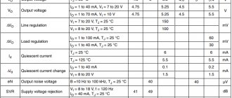
The characteristics of KREN12A, given in the technical descriptions (datasheet), should be considered taking into account the maximum power dissipation of the device. In any operating mode, it is not allowed to exceed it, and for stable operation it is necessary to provide appropriate cooling. Without using a radiator, the maximum power is limited by the case parameters - usually does not exceed 1 W. The voltage at the input of the microcircuit should always be 2-3 V greater than the output.
Maximum parameters
Here are the maximum parameter values for KREN12A:
- voltage: input up to 40 V; output from 1.25 to 37 V;
- output current 1.5 A;
- power dissipation up to 20 W;
- operating temperature range from 0 to +125 oC.
The specified values must not be exceeded.
Analogs
KREN12A has excellent functional analogues KR142EN12B (up to 1 A) and LM317T. Imported in some respects is considered better than domestic. Perhaps in connection with this, the Belarusian “Integral” has recently been producing similar devices with the “LM” marking. This is due to the great popularity of linear voltage stabilizers in the world, so foreign manufacturers are constantly improving them.
Roll stabilizer8b
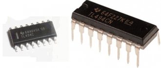
Currently, integrated voltage stabilizers are quite widespread. Power supplies using such stabilizers have a small number of additional elements, low cost and have excellent technical characteristics. The linear roll stabilizer 8b is one of the most common domestically produced options, which is an analogue of the imported stabilizers of the 78xx line.
Stabilizer action
The KR1428B stabilizer makes it possible to supply each board of a complex device with a separate stabilizing device and use a common source that is not provided with stabilization to power it.
Since the failure of one of the stabilizers leads to the failure of only the unit connected to it, this increases the overall reliability of the devices. Also, this connection scheme was able to solve the problem of combating pulsed noise and interference from long supply wires.
You should be aware that exceeding the current value for which the device is designed may result in failure of the stabilizer. However, modern stabilizers have current protection - if the maximum current load is exceeded, they simply turn off.
The disadvantages of linear stabilizers include strong heating under increased load. Thus, an increase in the input voltage entails overheating of the stabilizer. When developing the Kren8b stabilizers, this problem was solved by providing overheating protection.
Specifications:
- The KR1428B stabilizer has the following characteristics:
- permissible output current 1 Ampere;
- presence of internal thermal protection;
- protected output transistor;
- no need for external components;
- internal limitations of short circuit currents.
Application
Such a stabilizer can be used in devices such as:
- in radio-electronic devices as a power source for logical systems;
- in high quality playback devices;
- in measuring instruments.
By adding additional elements to typical circuits, you can turn the stabilizer from a voltage source into a source with regulation of both voltage and current.
If the length of the connecting wires of the stabilizer with filtering rectifier condensates exceeds 1 meter, then an electrolytic capacitor must be installed at its input.
Choosing a linear stabilizer Kren1428b will help solve the problem of voltage stabilization in a wide range of radio-electronic and other devices and will extend the life of the devices.
Voltage adjustment
Instead of one of the two resistors, you can use a potentiometer for KR142EN12A and get an adjustable switching circuit. With its help, the required voltage is achieved at the output of the microcircuit. Thus, at home, you can make a simple adjustable constant power supply stabilizer.
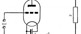
The figure below shows a simplified circuit for switching on bank 12a to stabilize 12V. With this connection, the load current is limited by the maximum parameters of the microcircuit and does not exceed 1 A. The power dissipation is determined by the area of the radiator - the larger it is, the better.
In this circuit, to lower the output voltage, resistance R2 is reduced. And vice versa, to increase - increase R2. The minimum possible value of R2 is 1 Ohm (1.25 V), and the theoretical maximum is up to 6.2 kOhm (35 V).
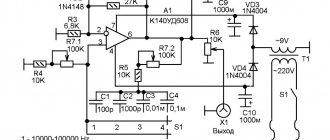
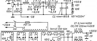
Of course, for a full-fledged regulated power supply (PSU), these components will not be enough. For example, to connect from a 220 V network, you also need a transformer, a rectifying diode bridge and smoothing capacitors. A simplified power supply diagram can be downloaded from the following
or
— a more advanced power supply design with the ability to obtain fixed voltages.
To increase the current in the load, powerful transistors are installed at the output of the microcircuit, but there is also the possibility of parallel connection.
Typical connection diagram KR142en5a
The KR142en5a series stabilizer with a constant positive output voltage of 5 V is widely used in a wide variety of electronic devices. Its scope of use is as a power source for logical systems, high-precision reproduction devices and other radio-electronic devices. The electrical circuit of KR142EN5A is shown in the figure below.
Capacities C1, C2 play a corrective role. C2 is designed to smooth out ripple, and C1 is designed to protect against possible high-frequency excitation of the microcircuit. The load current of the stabilizer is rated up to 2 A.
If you add auxiliary parts to the circuit, you can convert it into a voltage-regulated source. When KREN 142 is located remotely (with a connecting wire length of one meter or more) from the filtering capacitors of the rectifier, a capacitor should be connected to its input. An external divider is used to regulate the output voltage. For proper operation of the device, the use of an additional radiator will be required. These models are analogues of imported regulators of the 78xx series.
Pinout and connection diagram
The KR142en5a microcircuit is designed for a maximum current of 5 A, and it can provide it. But excess current threatens to damage the device. Below is an option for turning on the microcircuit. It is allowed to install the microcircuit twice and dismantle it once.
The circuit is fastened to the printed circuit board by unsoldering the case pins, see the pinout of the microcircuit in the figure.
Stabilizer characteristics
The kr142en5a microcircuit is a compensation-type stabilizer with an adjustable output voltage of positive polarity.
Main characteristics:
- overheat protection;
- short circuit current limitation;
- weight no more than 1.4 g;
- dimensions 14.48x15.75 mm.
Limit values of operating mode parameters and environmental conditions:
- Storage temperature -55 ... +150 C;
- Crystal temperature in operating mode -45 ... +125 C.
DIY 5 volt voltage stabilizer.
Roll 12 volt
The 12-volt bank voltage stabilizer, located in the power supply, is an important component of electronic equipment. Not so long ago, such units were based on zener diodes and transistors, which were replaced by specialized microcircuits.
The advantages of such circuits are the ability to operate in wide ranges of output current and output voltage, as well as the presence of a system that protects against electrical overloads and overheating - if the permissible temperature value of the microcircuit crystal is exceeded, the output current is stopped.
Specifications
The main characteristics of the 12 volt roll stabilizer include:
- no need for additional external components;
- presence of an internal thermal protection system;
- the presence of a protective circuit for the output transistor;
- internal short circuit current limiters;
- lightness and small dimensions.
The output current in Kren 12 stabilizing devices can be 1 or 1.5 A, the maximum voltage is 30 or 35 V. The difference between the input voltage and the output voltage in such stabilizers is always the same and is 2.5 V.
KR142EN12A
The KR142EN12A stabilizer and its analogue LM317 are adjustable stabilizing devices of the compensation type. They work with an external voltage divider in the measurement element, which allows regulation of the output voltage in the range of 1.3 V - 37 V. The control element is located in the positive power wire. The load current limit does not exceed 1 A.
These stabilizers are considered the most “high-voltage” in the K142 line and are highly resistant to pulsed power overloads. They also have a system that protects against output overcurrent.
The device is protected by a plastic housing with a built-in extended flange for heat dissipation. The mass of such devices does not exceed 2.5 g.
Application
12V stabilizers are widely used in electronic device circuits as components of their power supply sources. This can be household and measuring equipment, electronic equipment and other structures.
These stabilizers are also used by car enthusiasts when it is necessary to limit the battery charging current, check the power source, and install LED strips in car headlights to avoid frequent LED burnout.
The simplicity of the circuit design of the stabilizer makes it easy to use even for the average person who does not have special knowledge.