Yes, this is the good old K174UN7 (analogous to the A210K ТBA810AS, LA4420), but with a low power of 4 W, with the right circuit solutions you can get a fairly low level of harmonic distortion, less than 0.1% at 1000 Hz. First I came across the article “Gromov V., Radomsky A. Improving amplifier parameters on K174UN7.” - Radio. 1986. No. 9, 39-41″, then I discovered A. Zharonkin’s material “UMZCH with low distortion on IS K174UN7 Radio, 1987, No. 5, p. 54”, in the fall, on call, I left the capital with this small Bi-Amp and a “Sanken” cassette deck. To them I attached military orthogonal speakers of an extremely original design. A preamplifier with a two-way crossover were assembled on a uA741N. All boards were painted by hand using nitro varnish. The material below contains a modern view of the final amplifier manufactured using LUT. At the moment this amplifier is working for my neighbors. This is a board for HF channels; in the LF version there are plate radiators twice as large, covering the entire board space free of electrolytic capacitors.
An interesting feature - microcircuits from the same plant with a production difference of one year have different housings and marking directions! :laughing: scoop.
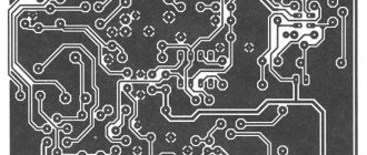
Amplifier assembly
The scheme is tested and working. This is a simple mono amplifier, assembled on a K174UN7 microcircuit. This chip requires a heatsink. Analogues of the microcircuit are TBA810AS and LA4420. A printed circuit board can be made using peroxide, this method is very affordable. Only for this board you need 200 ml of peroxide. The red line on the printed circuit board is its border; it must be erased before etching. The board can be powered from batteries, even 4 volts. The circuit also includes sound control using a 40 kOhm variable resistor.
It is easy to check the operation of the circuit. After connecting the power, you can touch the jack (amplifier input) with your finger. A sharp crackling sound with background noise will be heard in the speaker (amplifier output).
It's best to start soldering with wires and small components, such as ceramic capacitors or resistors.
The microcircuit must be installed on the radiator and soldered to the board.
The time for soldering one pin with one touch of the soldering iron is no more than a couple of seconds, then a break.
If the lead is poorly soldered, wait until it cools down, apply flux again and solder. The heatsink shields the heat a little, but to be on the safe side, soldering one contact should not take too long.
Typical connection of IS K174UN7
Rice. 1. Circuit of an audio amplifier based on the K174UN7 microcircuit.
This microcircuit is widely used in many amateur radio and industrial designs. Schemes based on it are simple, cheap and reliable.
Despite the low electrical parameters and quality indicators, in most cases this is sufficient, especially for small-sized and household equipment.
The amplifier described below has an output power of 4 W with a supply voltage of 15 V and a load resistance of 4 ohms. Input impedance 80 kOhm, current consumption up to 500 mA. The sensitivity of the amplifier is about 100 mV.
In all cases, the K174UN7 microcircuit can be replaced with A210K, MVA810B.
How to label a board
Part macros are applied to the board in the same way as traces. Using LUT.
However, this must be done after etching the tracks and drilling the holes. Accordingly, macros must be flipped horizontally before application. In the attached A4 file they are already reflected horizontally and are ready for application.
UMZCH on 174UN7 with a non-standard connection circuit
Rice. 2. UMZCH circuit for 174UN7 with a non-standard connection circuit.
Basically, this amplifier is made according to a standard circuit, but its load is connected to the IC power circuit. Due to this, some hanging elements are saved. The parameters are completely identical to the amplifier described above.
List of parts used
| C1 | 10 µF 6.3 V |
| C2 | 10 µF 16 V |
| C3 | 100 µF 16 V |
| C4 | 330 pF |
| C5 | 470 pF |
| C6 | 0.1 µF |
| C7, C8 | 100 µF 16 V |
| C9 | 2000 µF 16 V |
| C10 | 1000 µF 16 V |
| DA1 | K174UN7 |
| R1 | 15 kOhm 0.25 W |
| R2 | 150 kOhm 0.25 W |
| R3 | 47 kOhm variable |
| R4, R5 | 10 kOhm 0.25 W |
| R6 | 330 Ohm 0.25 W |
| R7 | 5.1 kOhm 0.25 W |
| R8 | 100 Ohm 0.5 W |
| R9 | 1 Ohm 0.5 W |
| R10 | 1 kOhm 0.25 W |
| VT1 | KT3102E |
UMZCH with low distortion on IC K174UN7
Currently, the problem of miniaturizing sound-reproducing equipment while simultaneously improving its technical characteristics is still acute.
One of the ways to solve it is the widespread introduction of integrated circuits (ICs). Unfortunately, their use does not always guarantee high quality. For example, power amplifiers built on the basis of the K174UN7 IC have a relatively high (up to 10% with an output power of 4.5 W) harmonic distortion coefficient. At various times, radio amateurs proposed circuit solutions that could reduce distortion to 1...2%, but this is not enough for high-quality 3H amplifiers. The author of the article managed to bring this parameter to 0.07...0.08% at a frequency of 1000 Hz. The reduction in distortion was achieved by introducing an additional amplifier stage and an OOS circuit (see figure). The OOS voltage is removed from a divider formed by resistor R10 (lower arm) and a resistor with a resistance of 4...6 kOhm (upper arm), located inside the IC and connected between pins 6 and 12.
An additional amplifier stage allows you to reduce the distortion introduced by the IC, since it makes it possible to increase the depth of feedback by increasing the resistance of resistor R10. The inevitable reduction in IC gain is compensated by an additional gain stage.
A further reduction in nonlinear distortion was achieved by connecting the OOS circuit (capacitor C8) between pin 6 of the IC and the connection point of resistors R4, R5 of the collector load of transistor VT1. In this case, the transistor itself is covered by a parallel OOS in voltage, and the difference between the input and output signals is received at its base. The input resistance of the amplifier becomes equal to the resistance of resistor R1, i.e. 15 kOhm. For the collector circuit of the transistor, the OOS voltage is a voltage boost, increasing the effective resistance of resistor R5 several times, which sharply increases the gain of the additional stage.
With the element ratings indicated on the diagram, the gain of the DA1 microcircuit is 4...6, and the cascade on the VT1 transistor is 10...12. Resistor R3 sets a symmetrical limitation of signal half-waves when the supply voltage changes within 5...15 V. In order to reduce (2...3 times) the harmonic coefficient at frequencies above 6000 Hz in the proposed device by 8 times. Compared to a typical connection circuit, the capacitance of capacitor C4 is reduced, which can lead to self-excitation of individual instances of the amplifier. In these cases, you should make a compromise and slightly increase the capacity of the mentioned capacitor. The load is switched on differently (again compared to the standard circuit). This is due to the desire to reduce the number of capacitors. The additionally introduced circuit R7C2 provides filtering of the supply voltage and reduces (by 1.5...2 times) distortions caused by its instability.
When prototyping the described amplifier, it was found that the sequence of connecting the pins of the parts to the common wire has a significant influence on the harmonic coefficient. It should be like this (from input to output): R3, R6, pin 9 DA1 NW. C4, R9, C9, pin 10 DA1. C 10. Capacitor C2 should be connected to the common wire at the point where resistor R3 is connected to it. It is also important that the terminals of resistors R1-R3 and the base VT1 are connected at one point.
GZ-107 audio frequency signal generator was used
and nonlinear distortion meter
S6-5
.
With a supply voltage of 12
and
15 V
, a load resistance of
4 Ohms
and an output voltage
of 3
and
4.3 V,
the harmonic distortion coefficient at a frequency of 1000 Hz was
0.07
and
0.1%
. The signal-to-noise ratio measured at the load is 79 dB relative to the nominal output voltage level of 3 V.
With a supply voltage of 12 V and an output of 3 V, the frequency response of the amplifier is in the range of 1000...16,000 Hz
horizontal, and at frequencies of 63 and 100 Hz it has a decline of 6 and 2.5 dB, respectively, which is due to the influence of capacitor C9.
When its capacitance increases to 10,000 µF,
the amplifier's frequency response is horizontal up to 20 Hz.
A. ZHARONKIN
Full text of the article with printed circuit boards