This article will describe the amplifier based on integrated circuits TDA1554q TDA1555q TDA1558q. The amplifier can be assembled both for sounding a room and for use in a car. Also, depending on the connection diagram, it can be a quad amplifier (4 channels), a three-channel amplifier (left-right and subwoofer) and two-channel (connecting two modes with different output powers). The amplifier based on these microcircuits provides protection for the output stage against short circuits, an on/off mode for the input signal (Mute), as well as protection against “clicking” when turning the power on/off.
Characteristics of TDA1554, 1555, 1558 series microcircuits, with index Q
Frab. …………………… 30-16000 Hz Fr. (for tda 1558q)……… 20-15000 Hz Up. ………………………… 6-15V Kharmon. (no more)….. 0.1% Ipot. (without supplying an amplifying signal) 30 mA Rn (no less) …………………… 2 Ohm Pout. for 2 Ohm load Pout. (Rн=4Ohm)………………… 4x11 W Pout. (Rн=4Ohm)………………… 2x22 W Pout. (Rn=4Ohm)……………1x22 and 2x11 W Uin (sensitivity)………500mV Rin…………………………….. 60 kOhm IC housing…….DBS 17 P
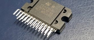
Rice. 1 Appearance of the microcircuit (the legs of the microcircuit are arranged parallel in two rows. Row 1 towards you from the side when you look at the markings has odd leg markings from left to right. Row 2 has even markings from left to right when looking at the chip designation)
The current consumption of the microcircuit is 3-4 A, this must be taken into account when choosing the cross-section of the supply wire, it must be at least 0.75 mm2. The microcircuit must be installed on a radiator with a developed area of about 500 square meters. see All input signal wires must be shielded. Do not route input signal wires near power wires. Correctly assembled circuits do not require adjustment.
Amplifier based on IC TDA1554Q
The amplifier is made on two TDA1554Q ICs, designed to operate in cascades connected in a bridge circuit, and has the following technical characteristics (according to the chip manufacturer and measurement results): sensitivity - 0.5 V, input resistance - 600 Ohms, nominal load resistance - 4 Ohms, nominal (maximum) output power 4x15 (4x22) W) with a nonlinear distortion coefficient of 0.25 and 10%, respectively, reproducible frequency band - 30...16000 and 15...25000 Hz with frequency response unevenness -1 and -3 dB, respectively. , supply voltage - 14.4 V, maximum current consumption - 14 A, quiescent current - 0.3 A, current consumption in standby mode - 0.001 A, readiness for operation when turned on - 5 s.
The diagram of the left channel of the amplifier is shown in Fig. 6. The right channel is completely identical to it. Elements C1-C5 and R1-R5 form separation filters. The amplifier is turned on when a control voltage of 12 V is supplied from the radio. When disconnected from the radio, the amplifier goes into standby mode. The main supply voltage is not switched, since the current consumed by the amplifier in standby mode is less than the self-discharge current of the car battery. Circuit R6C9 provides a turn-on delay. LC filters are used to filter noise in the power supply circuits of microcircuits. The high-capacity capacitor C10 in the power filter prevents voltage drop during power peaks and is installed directly in the amplifier housing. The input signal is supplied via a shielded cable with a BNC bayonet connector.
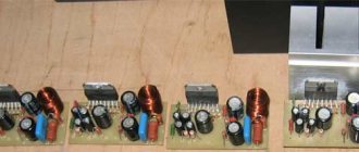
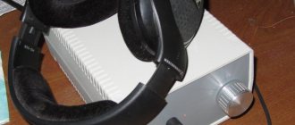
The power amplifier is assembled on a printed circuit board, the filters are mounted. The microcircuits and the board are placed on a duralumin corner - a heat sink. Cooling of the amplifier chips is forced using a fan from the computer power supply. The amplifier is installed in the front part of the cabin on a shelf under the glove box.
If the amplifier will be connected directly instead of the dynamic heads of the radio, its signal level should be adjusted very carefully, starting from zero, so as not to overload the inputs of the microcircuit.
In the case when the device with which the amplifier is supposed to be used has an output stage made according to a bridge circuit, oxide capacitors with a capacity of 10 μF must be connected between its output and the filter board, and their positive terminals must be connected to the input jacks.
When installing the amplifier, fixed resistors MLT-0.25 and variable resistors .SP3-12a can be used. The amplifier's oxide capacitors are K50-18 (C10) and K50-24 (C7-C9), the rest are any ceramic ones. The power filter coil L1 is wound on a ring magnetic core with dimensions of 20x10x8 mm made of 2000NN ferrite and contains 5 turns of mounting wire with an internal core cross-section (without insulation) of 1...1.5 mm2.
The L1 coil of the acoustic system is wound on a 2000NN ferrite rod with a diameter of 8 and a length of 20 mm and contains 15 turns of PEV-1 1.0 wire. Capacitors C1-C2 - KBG-MN, C3.C4 - K50-24, resistors PEV - 5 W.
Literature:
- Elyutin A. Gender issues - “Master 12 Volt” No. 1997/1998 p.20-23
- Elyutin A. Do you need a strong rear - “Salon AV” No. 3/1998 p.84-87
- Shikhatov A. Passive tone controls - Radio, 1999, No. 1 p. 14-15.
- Ageev S. Should the UMZCH have a low output impedance? - “Radio” No. 4/1997 pp. 14-16.
List of radioelements
| Designation | Type | Denomination | Quantity | Note | Shop | My notepad |
| DA1 | Audio amplifier | TDA1554Q | 1 | Search in the Otron store | To notepad | |
| C1, C2 | Capacitor | 0.47 µF | 2 | Search in the Otron store | To notepad | |
| C3 | Capacitor | 2200 pF | 1 | Search in the Otron store | To notepad | |
| C4, C5 | Capacitor | 0.68 µF | 2 | Search in the Otron store | To notepad | |
| C6 | Capacitor | 0.1 µF | 1 | Search in the Otron store | To notepad | |
| C7 | Electrolytic capacitor | 470 µF 16 V | 1 | Search in the Otron store | To notepad | |
| C8 | Electrolytic capacitor | 100 µF 16 V | 1 | Search in the Otron store | To notepad | |
| C9 | Electrolytic capacitor | 220 µF 16 V | 1 | Search in the Otron store | To notepad | |
| C10 | Electrolytic capacitor | 22000 µF 16 V | 1 | Search in the Otron store | To notepad | |
| R1, R2 | Resistor | 1.3 kOhm | 2 | Search in the Otron store | To notepad | |
| R3 | Resistor | 15 kOhm | 1 | Search in the Otron store | To notepad | |
| R4, R5 | Variable resistor | 100 kOhm | 2 | Search in the Otron store | To notepad | |
| R6 | Resistor | 36 kOhm | 1 | Search in the Otron store | To notepad | |
| L1 | Inductor | 1 | Search in the Otron store | To notepad | ||
| Add all | ||||||
Tags:
- ULF
Diagram of a two-channel amplifier based on TDA1554Q, TDA1555Q, TDA1558Q chips
This diagram is presented for a two-channel connection. It is worth noting that since independent amplifiers (4 separate ones in the microcircuit) operate in antiphase, when the microcircuit is connected, the output power will be maximum, that is, 22 W, unlike if each individual channel is connected to ground. That is, when connecting 6-ground and 12-ground speakers, we get a two-channel amplifier with a power of 11 W.
Rice. 2 Two-channel amplifier circuit
Computer amplifier based on TDA1554
In this article, we suggest you assemble an audio amplifier circuit with your own hands. Initially, this project was considered as a simple audio amplifier circuit for a computer, but in principle, it can be used as a booster in a car audio system and for satellite speakers in a home theater system, and other options are possible.
The wiring of the “heart of the system,” the TDA1554 integrated circuit, is very simple and not expensive. You can verify this by examining the presented audio amplifier circuit.
As can be seen from the diagram, it does not have the ability to adjust the sound level, this is not a problem, if we use a sound amplifier for a computer, it is possible to adjust the sound signal level using the operating system and the player you are using. If the amplifier is used in other applications, the sound level is adjusted using the pre-amplifier controls.
The audio amplifier circuit is designed to work with 4 ohm speakers, but it will also work with 8 ohm speakers.
The TDA1554 chip dissipates about 28 W of heat at maximum load, so it needs a good heat sink and should be installed on a good heatsink.
The consumption of the TDA1554 computer amplifier does not exceed 60W at a supply voltage of 12 V, at full volume, which indicates its fairly high efficiency. As a power source, it is necessary to select a unit capable of providing the appropriate power at its output. When setting up, you can use the block available on our website.
On the Internet you will find many audio amplifiers for your computer, but this TDA1554 circuit is apparently the simplest of those that can provide high-quality sound to your favorite songs.
The output power of the amplifier is about 22 W, which is more than enough for a computer audio amplifier. But, nevertheless, if this seems not enough for you, turn your attention to the TDA7294 home amplifier.
And one more piece of advice: when making a circuit board, try to arrange the elements as compactly as possible in order to eliminate various interferences in the circuit that affect the sound quality. But do not place the elements too tightly to ensure their normal natural ventilation.
list of files
TDA1554Q.pdf
Description of the TDA1554 chip
- Downloads: 732
- Size: 111 Kb
Rate this article Rating 4.64 (11 Votes)
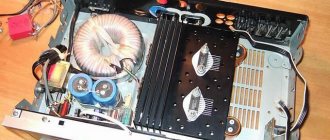
Details and design
The case is made from an old faulty Chinese car radio “SUNNY”. The front panel of the radio was removed and a black plastic plate was installed in its place, on which the S1 switch and X1 socket are located. The radiator is the iron casing of a former car radio. You need to place the A1 chip on the radiator.
Coil L1 is wound on a ferrite ring with a diameter of 28 mm, - 30 turns of PEV 1.0 wire. For installation, a dismantled printed circuit board of a faulty car radio (from which the housing comes) is used. Installation on it is carried out partly by printing, partly by volumetric method.
Poptsov G. RK-11-2018.
Schematic diagram
And so, the circuit diagram is visible in the figure. The amplifier is based on the TDA1554Q chip, which contains a two-channel bridge power amplifier that develops power up to 22W per channel.
The advantages of the microcircuit include the extreme minimum of “piping” and a bridge circuit of the output stages with a minimum constant voltage potential between the outputs, allowing you to connect speaker systems without isolating capacitors. This helps improve reproduction at low frequencies and reduce the size of the amplifier.
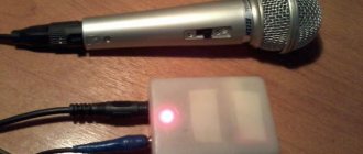
In addition, this microcircuit is widely used in car audio equipment, and here it is just in place. X1 is a standard 3mm telephone jack.
To connect to the tablet, a special cable with 3 mm stereo plugs is used at both ends. To normalize signal levels, the circuit has two trimming resistors R3 and R4.
Rice. 1. Schematic diagram of an AF power amplifier for a tablet or smartphone on a TDA1554Q chip.
Microcircuit A1, when operating at maximum power, consumes significant current. To prevent the switch from burning out, it is simply not in the circuit, A1 is constantly connected to the car's on-board network (via inductance L1), and switch S1 changes the voltage at pin 14 of A2, transferring A2 to the energy-saving “off” state.
Installation and connection
Powerful speakers, low-frequency or broadband, are connected to terminals 5-6 and 9-10. Additional MF-HF-AS are connected to the remaining terminals.
Output power for bridge outputs (terminals 5-6 and 9-10) is 22 W each. The remaining outputs are 11 W each. The impedance of the speaker systems is at least 4 ohms each. All capacitors must be at a voltage not lower than the power source. The power supply voltage can be from 6 to 16V, and the output power changes accordingly.
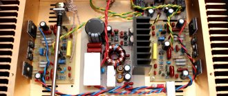
Installation is carried out without a printed circuit board. The microcircuit is mounted on a massive radiator, which is the rear wall of the ULF housing. And the installation is done directly on its terminals. Electrolytic capacitors are additionally fixed in the housing using Moment glue.
Poptsov G. RK-2017-04.