According to its characteristics, the K157UD2 microcircuit (analogous to LM301) is a Soviet two-channel low-noise operational amplifier (op-amp) for general purposes, having a medium accuracy class.
It allows the use of a wide range of differential input voltages and has built-in short circuit protection. Can work with both unipolar and bipolar power supplies from 3 to 18 V.
This op-amp began to be produced in the distant 80s in the USSR at the Kiev enterprise of the Research Institute of Microdevices, and subsequently at the IC “Logic” software in Ivano-Frankovsk. Many radio amateurs consider it the flagship of Soviet industry in its segment. Now the device is inevitably outdated, but has not ceased to be popular for creating various solutions in audio equipment.
Main settings
If you look closely at the electrical characteristics of the K157UD2, you will notice that in terms of performance, this microcircuit is not for use in audio devices. Thus, the highest rate of voltage rise at its output is 0.5 V/µs, which is comparable to an output signal of up to approximately 10 V/8 kHz. In real life it will be even lower. But for its time it was also a good indicator.
Maximum values
Here are the main limit values of the parameters:
- maximum power supply (UPit) up to ±18 V;
- output voltage (Uout max.) up to ± 13 V (at Upit = ± 15 V);
- zero offset voltage (U cm) up to ± 13 V;
- current consumption (I sweat) up to 7 mA;
- short circuit current (I short circuit) up to 45 mA;
- cutoff frequency (f srz) from 1 MHz;
- gain (KуU): no less than 50000 (at f =0...50 Hz) and 800 (at f =20 kHz);
- output slew rate (VUout) of at least 0.5 V/µs.
Exceeding the maximum permissible values may lead to device failure.
The typical value of the noise voltage used at the input of this op-amp (in the frequency range from 20 to 20,000 Hz) is no more than 1.6 μV.
Analogs
It is believed that the imported analogue of the K157UD2 is LM301. But, firstly, this microcircuit has 8 pins, instead of 14. Therefore, to replace it you will have to look for two such devices. Secondly, they will be very difficult to find in our stores.
What else can replace K157UD2? A good alternative for this device is the new LME49XXX series microcircuits. More precisely, in most cases the following are suitable: LME49720, LME49860 and LM4562. They are very similar in their characteristics to the one under consideration, they have good linearity and bandwidth (up to 90 Hz), not only at a gain of 1, but also significantly higher (1000 and higher).
Typical noise voltage in the frequency range from 20 to 20,000 Hz is within 0.4 μV. Domestic analogues: KR1434UD1A and updated modification K157U D3. The problem is that now they are difficult to find on Russian shelves and they are more expensive.
Four circuits on K157UD2
The K157UD2 microcircuit is rightfully considered one of the most popular microcircuits among Russian radio amateurs. Based on it, you can assemble a huge variety of devices. Using this microcircuit as an example, we will consider four schemes that can be repeated even by novice radio amateurs.
Briefly about the microcircuit
The supply voltage is bipolar from 3 to 15V, and the microcircuit also works well when powered from a unipolar source from 2.5 to 30V.
The gain of one channel is: At a frequency of 0 – 50 Hz – 50,000, 20 kHz – 300 – 800. The self-noise level is no more than 1.6 mKV in the frequency band 20 – 20,000 Hz. The microcircuit is protected against short circuit at the output.
Microcircuit pinout.
Amplifier stage
Scope of application: pre-amplifiers in stationary (option 1) and portable equipment (option 2).
Parameters: Uin————————————————5mV Frequency range———————-25-20000 Hz. Distortion level (no more)——-0.1% (in a bridge circuit no more than 0.3%). Uout———————————————250mV
These parameters fully apply to the second version of the circuit, as well as to bridge connection.
Option 1: with bipolar power supply:
Option 2: single-supply
Bridged amplifier circuit
Scope of application: output stages of low-power equipment (receivers, headphone amplifiers). The circuit works optimally with headphones with an impedance of 32 ohms or higher.
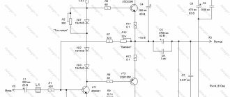
Direct amplification receiver for DV or MV range
Parameters: Received frequency range 525-1605 kHz Sensitivity no less than 10 µV.
Scope of application: radio reception. The receiver is designed to receive signals from local radio stations; good reception of distant radio stations is possible in the evening and at night.
L1 80-100 turns NE range, L2 5 – 8 turns.
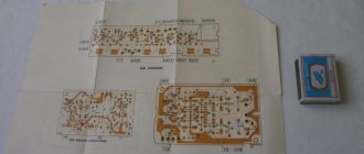
In conclusion: all the above diagrams were collected by me and are 100% working.
List of radioelements
| Designation | Type | Denomination | Quantity | Note | Shop | My notepad |
| Option 1: with bipolar power supply | ||||||
| DA1 | Operational amplifier | K157UD2 | 1 | Search in the Otron store | To notepad | |
| C1 | Capacitor | 15 pF | 1 | Search in the Otron store | To notepad | |
| C2 | Capacitor | 0.01-0.022 uF | 1 | Search in the Otron store | To notepad | |
| C3 | Capacitor | 0.1 µF | 1 | Search in the Otron store | To notepad | |
| R1 | Resistor | 3.3-4.7 kOhm | 1 | Search in the Otron store | To notepad | |
| R2 | Resistor | 150-270 kOhm | 1 | Search in the Otron store | To notepad | |
| R3 | Resistor | 2.7 kOhm | 1 | Search in the Otron store | To notepad | |
| Option 2: single-supply | ||||||
| DA1 | Operational amplifier | K157UD2 | 1 | Search in the Otron store | To notepad | |
| C1 | Capacitor | 10-68 pF | 1 | Search in the Otron store | To notepad | |
| C2 | Electrolytic capacitor | 10 µF | 1 | Search in the Otron store | To notepad | |
| C3 | Capacitor | 0.1 µF | 1 | Search in the Otron store | To notepad | |
| C4 | Capacitor | 10 µF | 1 | Search in the Otron store | To notepad | |
| C5 | Capacitor | 0.022 µF | 1 | Search in the Otron store | To notepad | |
| R1 | Resistor | 100-220 kOhm | 1 | Search in the Otron store | To notepad | |
| R2-R3 | Resistor | 82-150 kOhm | 2 | Search in the Otron store | To notepad | |
| R4 | Resistor | 2.7 kOhm | 1 | Search in the Otron store | To notepad | |
| Bridged amplifier circuit | ||||||
| DA1 | Operational amplifier | K157UD2 | 2 | Search in the Otron store | To notepad | |
| C1, C2 | Capacitor | 15 pF | 2 | Search in the Otron store | To notepad | |
| C3, C4 | Capacitor | 0.1 µF | 2 | Search in the Otron store | To notepad | |
| C5, C6 | Capacitor | 470 µF | 2 | Search in the Otron store | To notepad | |
| C7 | Capacitor | 10 µF | 1 | Search in the Otron store | To notepad | |
| C8, C9 | Capacitor | 0.01 µF | 2 | Search in the Otron store | To notepad | |
| R1, R2, R9 | Resistor | 150 kOhm | 3 | Search in the Otron store | To notepad | |
| R3, R4 | Resistor | 2.7 kOhm | 2 | Search in the Otron store | To notepad | |
| R5-R8 | Resistor | 100 kOhm | 4 | Search in the Otron store | To notepad | |
| Direct amplification receiver for DV or MV range | ||||||
| DA1 | Operational amplifier | K157UD2 | 1 | Search in the Otron store | To notepad | |
| C1, C2, C4, C5, C7, C8 | Capacitor | 0.01 µF | 6 | Search in the Otron store | To notepad | |
| C3, C9 | Capacitor | 10 pF | 2 | Search in the Otron store | To notepad | |
| C6, C10 | Electrolytic capacitor | 10 µF | 2 | Search in the Otron store | To notepad | |
| C11 | Variable capacitor | 25-125 pF | 1 | Search in the Otron store | To notepad | |
| R1, R2, R6, R7 | Resistor | 82-100 kOhm | 4 | Search in the Otron store | To notepad | |
| R3 | Resistor | 120 Ohm | 1 | Search in the Otron store | To notepad | |
| R4, R9 | Resistor | 200 kOhm | 2 | Search in the Otron store | To notepad | |
| R5 | Variable resistor | 10 kOhm | 1 | Search in the Otron store | To notepad | |
| R8 | Resistor | 2.7 kOhm | 1 | Search in the Otron store | To notepad | |
| L1 | Inductance | 1 | 80-100 turns | Search in the Otron store | To notepad | |
| L2 | Inductance | 1 | 5-8 turns | Search in the Otron store | To notepad | |
| Add all | ||||||
Tags:
Where to unsolder
K157UD2 can be removed from old Soviet equipment, where it was widely used until 1995. It is believed that devices before 1991 are of higher quality and more stable in operation, while their noise characteristics are better (at least -80 dB). And there are plenty of negative reviews for models released after 1992. It is the latest versions that are defective, often fail and are the noisiest (-48…- 75 dB).
Characteristics
Now let's move on to considering the technical characteristics of the K157UD2 microcircuit:
- Optimal supply voltage Upit = ± 15 V;
- Supply voltage range Upit = from ± 3 to 18 V;
- The highest voltage at the output (with such initial parameters Upit = ± 15 V, Uin = ± from 25 to 200 mV) Uout max≥ ±13 V;
- Bias voltage (measured at Upit = ± 15 V, Uout ≤ 1.2 V) Ucm ≤ ±5 mV;
- Input current (measurement modes Upit = ± 15 V, Uout ≤ 2.2 V) Iin ≤ 500 nA;
- Input current difference (measurement modes Upit = ± 15 V, Uout ≤|2.2| V) Iin diff ≤ 150 nA;
- Current consumption (measured at Upit = ± 15 V) I ≤ 7 mA;
- Short-circuit current (measurement modes Upit = ± 15 V, Uin = ± (from 20 to 180) mV) Ic ≤ 45 mA;
- Voltage amplification kit Upit = ± 15 V: Uout = ±10 V, f = from 0 to 50 Hz - Ku ≥ 50*10³;
- Uout = ±7 V, f = 20 kHz Ku ≥ 300;
It has a mean time between failures of 50,000 hours. All data was obtained as a result of testing at a temperature of +25°C.
According to reference books, K157UD2 contains 0.00398 g of gold.
Application
This microcircuit was widely used in various signal generators (sine wave, saw, etc.), mixers, equalizers, tone blocks, hearing aids, intercoms and even power supplies. It is common in preliminary audio frequency amplification stages (20-20000 Hz), stereophonic household and studio recording and playback equipment, magnetic heads of tape recorders, etc. Widely known and popular
, where NE555, irfs630 or irf740 transistor are also used. But despite all the advantages, according to the stated characteristics it is still inferior to modern op-amps.
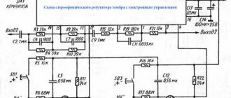
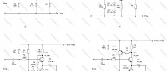
Switching circuits K157UD2
Now let's look at a typical connection diagram for the K157UD2 IC. In order to ensure the stability of the operation of an operational amplifier (op-amp), which has a negative feedback loop (NFL), it is necessary to connect capacitors to the correction terminals. Their capacity depends on the depth of the environmental protection. For the first amplifier these are legs 1 and 14, for the second 7 and 8.
It is also possible to connect a correction capacitor between pins 1 and 13 for the first op-amp and 7 and 9 for the second. A third version of the circuit is also possible, where capacitors are connected between legs 1 (for the first amplifier) and 7 (for the second) and the common wire. If the wires supplying power to pins 11 and 4 of the IC are long, then a blocking capacitor must be used.
Scheme
The connection circuit for the k157ud2 is quite simple. Or rather, there are several typical options for using it to amplify sound signals. Depending on the voltage source, you can assemble an amplifier with unipolar or bipolar power supply. The figure below shows connection examples.
An example of how the pre-amplifier is implemented on the k157ud2 can be seen in the video.
DataSheet
| Conventional graphic designation of IC K157UD2 | Electrical circuit diagram |
| Schematic diagram of the inverting amplifier: Ku, U = R3/R1 | Schematic diagram of a non-inverting amplifier: Kу,U = 1 + R1/R2 |
| Schematic diagram of a sinusoidal voltage generator with an amplitude stabilizer: ƒ = 1/2πRC | Schematic diagram of a playback amplifier for a portable stereo cassette recorder |
| Schematic diagram of a preamplifier-corrector for an electromagnetic pickup (14) | Schematic diagram of a recording amplifier for a stereo cassette recorder (15) |
| Schematic diagram of a rectangular pulse generator ƒ = 1/2RC1n(1 + 2R2/R1) | Housing type 201.14-1 |
Description
The chips are low-noise, two-channel operational amplifiers of medium precision. They have protection against short circuits at the output. Contains 53 integral elements. Housing K157UD2 type 201.14-1, weight no more than 1.22, KB157UD2-4 - unframed. Purpose of the K157UD2 pins: 1 - correction of the 1st channel; 2 — non-inverting input of the 1st channel (+); 3 — inverting input of the 1st channel (—); 4 — food (-Up); 5 — inverting input of the 2nd channel; 6 — non-inverting input of the 2nd channel; 7—correction of the 2nd channel; 8 — correction of the 2nd channel; 9 — input of the 2nd channel; 11 — power supply (+Up); 13 — output of the 1st channel; 14 — correction of the 2nd channel.
| Electrical parameters | ||||
| Options | Conditions | K157UD2 | KB157UD2-4 | Unit change |
| Rated supply voltage | — | ±15 | ±15 | IN |
| Maximum output voltage | at Up = ±15 V, Uin = ±(25…200 mV) | ≥±13 | ≥±13 | IN |
| Zero offset voltage | at Up = ±15 V, Uout ≤ |1.2| IN | ≤±5 | ≤±5 | mV |
| Input current | at Up = ±15 V, Uout ≤ |2.2| IN | ≤500 | ≤500 | on |
| Input current difference | at Up = ±15 V, Uout ≤ |2.2| IN | ≤150 | ≤150 | on |
| Consumption current | at Up = ±15 V | ≤7 | ≤7 | mA |
| Short circuit current | at Up = ±5 V, Uin = ±(20…180) mV | ≤45 | ≤45 | mA |
| Voltage Gain | at Up = ±15 V, Uout = ±(10±0.5) V, f = 0…50 Hz | ≥50×103 | ≥50×103 | — |
| at Up = ±15 V, Uout = (7±0.5) (eff.) V, f = 20 kHz | ≥300 | ≥300 | ||
| Common mode attenuation ratio of input voltages | at Up = ±15 V, Uin = 1 V (eff.), f ≤ 50 Hz | ≥70 | ≥70 | dB |
| Coefficient of mutual penetration of signals from channel to channel | at Up = ±15 V, Uout = 7 V (eff.), f = 1 kHz | ≤-80 | ≤-80 | dB |
| Average temperature drift of zero offset voltage | at Up = ±15 V, T = -25..+70 °С | ≤±50 | ≤±50 | µV/°C |
| Average temperature drift of input current difference | at Up = ±15 V, T = -25..+70 °С | ≤±5 | ≤±5 | nA/°C |
| Unity gain frequency | at Up = ±15 V, Uin = 9…10 mV, Uout = 9…10 mV (eff.) | ≥1 | ≥1 | MHz |
| Maximum slew rate of output voltage | at Up = ±15 V, Uout = ±(10…11) V, f = 5…10 kHz | ≥0,5 | ≥0,5 | V/μs |
| Maximum permissible operating conditions | ||||
| Options | Conditions | K157UD2 | KB157UD2-4 | Unit. |
| Supply voltage | — | ±(3…18) | ±(3…18) | IN |
| in extreme mode | ±20 | ±20 | ||
| Voltage at the inputs relative to the common terminal of the switching circuit | — | ≤8,5 | ≤8,5 | IN |
| Power dissipation 1 for both channels | — | ≤500 | ≤500 | mW |
| Load resistance | — | ≥2 | ≥2 | kOhm |
| Ambient temperature | — | -25..+70 | -25..+70 | °C |
1 At T > 25 ° C, the dissipated power is calculated by the formula Pdis, mW = (125—T)/0.22 ° C/mW.
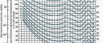
| Dependence of voltage gain on frequency | Dependence of output voltage on frequency |
| Dependence of current consumption on supply voltage | Dependence of input current on supply voltage |
| Dependence of the input current difference on the ambient temperature |
If you find an error, please select a piece of text and press Ctrl+Enter.
Analogs
The most complete analogue of K157UD2 is the KR1434UD1A microcircuit. It is packaged in the same case and has the same pinout. The electrical parameters are also completely identical. Accuracy class – average. The only difference is that the microcircuit proposed for replacement can be powered from a voltage source of up to 22 V.
Also, the IC in question can be replaced with K157UD3. This model is similar to the original one in all respects. However, it has a lower noise level and therefore, using it, you can get better amplifier performance.
Also, the K157UD2 can be replaced with a dual operational amplifier KR140UD20B. There are no completely identical devices among foreign products. You can only select based on functional characteristics. For example, install two single LM301 operational amplifiers.
Microphone amplifiers
Microphone amplifiers are used to amplify small signals (0.2-2 mV) to a level of 0.1-0.3 V. The input impedance of the microphone amplifier, which provides the maximum signal-to-noise ratio, is selected 3 times higher than the internal one resistance. Since the magnitude of the EMF developed by the microphone is small, it is necessary to ensure a minimum noise level in the microphone amplifier referred to the input. Thus, with a useful signal at the input equal to 1 mV, to obtain a signal-to-noise ratio of 60 dB, it is necessary to ensure that the noise level of the microphone amplifier referred to the input is no more than 1 μV. Another important requirement for a microphone amplifier is the need to have an overload margin of at least 26 dB, which reduces the likelihood of significant nonlinear distortion of the amplified signal. The circuit implementation of a microphone amplifier is quite simple when using an operational amplifier. The operational amplifier should be selected based on the minimum noise level applied to the input. Of the domestic operational amplifiers, the most suitable are the KM551UD2A (Uin noise - 1 µV) and K157UD2 (Uin noise = 1.6 µV). Of the foreign operational amplifiers, we can recommend the NE5532.
Figure 1 shows the circuit of a microphone amplifier based on an operational amplifier. The microphone amplifier has the following parameters: Nominal input voltage, mV 1 Nominal output voltage, mV 100 Signal to noise ratio, dB 56 Operating frequency range, Hz 30-30000 Harmonic coefficient, % 0.05 Maximum output voltage, V 7 Input impedance, kOhm 1 The operational amplifier is connected in an inverting amplifier circuit. The gain is determined by the ratio of resistors K1/K2 and is equal to 100. When replacing the operational amplifier K157UD2 with KM551UD2A, the signal-to-noise ratio will increase to 60 dB.
Figure 2 shows a diagram of a microphone amplifier with a balanced input. Balancing is ensured by connecting transformer T1 at the input. With this circuit design, the noise immunity of the amplifier is improved. As T1, you can use a transformer with a ratio of turns of the primary and secondary windings from 1:7 to 1:10 and with a primary winding resistance to alternating current of 0.6-1 kOhm.
Figure 3 shows a diagram of a microphone amplifier with a balanced input, in which the functions of a transformer are performed by a differential amplifier based on the operational amplifier BA1. The adder of two signals is assembled on OA2. The higher the degree of matching of resistors KZ and K4, Kb and K7, K8 and K9, K10 and K12, K11 and K13, the greater the suppression of interference. The microphone amplifier has the following parameters: Nominal input voltage, mV - 2 Nominal output voltage, mV - 100 Signal-to-noise ratio, dB - 60 Harmonic coefficient, % - 0.05 Reproducible frequency range, Hz - 30-30000 Minimum load resistance, kOhm 10 The gain of the microphone amplifier depends on the position of switch 81. When the switch is open, K = 50, when closed - 100. A stabilized source with low ripple voltage or a battery is used to power the microphone amplifier.