↑ Circuit and board
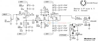
The scheme is simple:
After listening and comparing, I realized that the device has the right to live.
The gain is sufficient to use with any headphones. I separated the printed circuit board of the amplifier itself and the power supply separately. The internal height of the case is 53 mm. In this regard, it was decided to place the amplifier board vertically, because in its normal position, the height of the board with the lamp is about 7 cm. Here is the amplifier board.
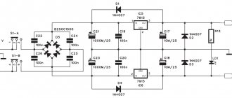
And this is the power supply board.
Pay attention to how the “ground” is spread out on it. Everything is reduced to one point at minus el. capacitor standing first after the diode bridge. Transferring the parts from the breadboard to the boards was not difficult.
The network transformer used a power of 40 watts. Primary winding 220 V. Secondary: 26, 11, 6.7 Volts. 26V is for the anode voltage, and 6.7V is for the lamp filament.
This is what the assembled boards look like.
Listening after assembly showed that everything was assembled correctly, there was no background.
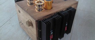
All that remains is to assemble it all into the body. Like that.
And here is the finished version of the assembly.
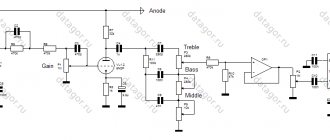
↑ Tube buffer for 6N23P
Let's move on to the buffer that has caused the most controversy and negative reviews.
The triode connection circuit is not entirely standard. Here are the main objects of criticism: relatively low power supply and it is “bipolar”, “at such voltages and currents, the lamp operates in the curved part of the current-voltage characteristic and the signal will be asymmetrical.” For some reason, almost everyone who wrote their opinion on “Corsair” is “theoretically” sure that it won’t work like that. My theory and practice told me otherwise.
Firstly, the 6N23P lamp also works at lower voltages. There are many amplifier circuits with power supply below 30 Volts. Secondly, “bipolar” power supply for lamps is also not exotic, of course not at every step, but such circuits do occur. And thirdly, work in the curved part of the current-voltage characteristic. I am used to using the concept “volt-voltage characteristic” in relation to a circuit with a resistive load, i.e. where the output signal is greater than the input signal. In this circuit we have a cathode follower (no voltage gain). It was not clear to me how the current-voltage characteristic fits into this in terms of symmetry. Just in case, I looked and re-read the theory of cathode followers. I couldn’t find a current-voltage characteristic in relation to the symmetry of the signal anywhere in the calculations. In a cathode follower, Kus is slightly less than one, in other words, the circuit does not amplify, and therefore there should be no voltage asymmetry. Theoretically, current asymmetry is possible, but at such low currents it is also unlikely. In general, on these three points, there was a discrepancy between other people’s opinions and my experience.
↑ Installation nuances
Now let's look at some important aspects of the build. Look closely at the following photo.
Everything is in order. The network connector on the rear panel has a built-in fuse, and the ground pin is immediately attached to the case. Then the wire to the power supply is passed in three turns through a ferrite ring. The voltage is supplied through the switch to a standard surge protector, and from there to the screw terminals.
All wires carrying alternating voltage are twisted. So the red wires are the primary winding of 220 Volts. Orange wires - the secondary winding of 26 Volts goes to the screw terminals, then the rectifier, stabilizer and filter. Pay attention to the lower right corner of the PSU. The minus power supply is not connected
directly with the device body, and through a 100 Ohm resistor to the screw stand to the body, this is important!
Next, the yellow and black wires are 24 Volts of stabilized voltage to power the amplifier. The signal lines are made of colored wires from a computer network cable; they are also interconnected and located perpendicular to the power lines of the amplifier. The short wire from the volume control is shielded. The blue-white wire powers the amplifier power-on LED.
On the rear panel there is a network input connector with a built-in fuse, input connectors that do not have a common contact with the case.
On the front panel there is a volume control, a power switch with a backlit power indicator and a headphone jack.
The incandescent wires, green, are twisted and soldered directly to the lamp socket.
Now run-in, warm up and listen to the amplifier.
This is the picture we see on an oscilloscope when a 1 kHz 300 mV signal is applied to the input at full volume.
Agree that it’s not even bad! That's all, close the case and enjoy your favorite music!
↑ Let's start with UMZCH
Circuit diagram for LM3886. The only thing wrong with it is the very large Kus
. With the ratings of the original source, the Kus was about 45. Practical testing showed that with the specified power supply (+-27 V), sine wave distortion at a load of 8 ohms begins at approximately 16.5 V at the output. (i.e. 34 W).
The output signal level in modern technology is about 1.2 -1.5 V. Thus, it was decided to make a Kus of about 16 (with a small reserve). In this scheme, Kus can be calculated using the formula:
Ku=(R9/R8)*(R7/(R5+R4))
The next point is the T-shaped OOS
, applied in the circuit. It also, it is not clear why, caused negative reviews. I looked about T-shaped OOS and everything connected with them. I didn’t see anything criminal in her. To simplify, Kus depends on the ratio of the OOS resistance to the input resistance. In a classic OOS (resistor from the output to the input input), in order to get a Kus of about 16, the resistor in the OOS must be quite large. But the larger the OOS resistor, the less stable the maintenance of “0” constant voltage at the output is. T-shaped OOS allows you to avoid this negative point. And this is not so exotic, T-shaped OOS is quite common. Therefore, I decided to leave her alone.
A few words about “0”
(constant voltage) at the output. Resistor R6 is responsible for this. In principle, you can simply connect pin 10 to ground, which is found in many circuits. The output voltage will be about 150 mV. But according to the datasheet, this is not recommended. Therefore, I turned on the interlinear instead of R6 and tried to select “0” at the output with it. The resistor turned out to be 3.82 kOhm. Next, instead of the trimmer, the closest nominal value at 3.9 kOhm was soldered in. The constant voltage at the output was 10 mV. Quite a decent result.
"Mute" mode.
Pin 8 is responsible for this, to which you need to apply a negative voltage. This voltage is supplied through R10 and smoothed out by C9. For some reason, this method also caused “theoretical” dissatisfaction. It was argued that with this method, power ripples penetrate the microcircuit with all the negative consequences. Instead of R10, it was proposed to install a current source on a field-effect transistor. Defenders of R10 claim that the control transistor inside the LM3886 is in deep saturation and ripple, even if they theoretically penetrate through R10 + C9, they cannot affect the sound in any way.
I tested both methods. I didn't find any difference. In general, you can install it as in the diagram R10 + C9, you can use the current source on the field switch. I left the field worker with me. I was just too lazy to solder it. In this case, you don’t have to install C9. Current source circuit
Here’s a primitive one:
The “mute” mode is turned off using the relay of the protection unit.
Those. There is a delay when turned on. Relay is off. With one group of contacts it connects -27V to the LED via R13. After the delay time has passed, this group of contacts turns off the LED and closes the “mute” circuit to -27V, thus turning on the sound. Other groups of contacts connect the speakers to the amplifier output. The remaining elements of the LM3886 harness have a clear purpose; I will not describe them. So we've sorted out the right side of the amplifier circuit. In essence, this is a standard connection of the LM3886 in inverting mode.
Money issue
I'll start with perhaps the most piquant issue - price. There is no doubt, a decent tube amplifier for less than 20 thousand rubles is really not expensive at all. However, everyone knows how to search on the Internet, and it is no secret that in Russia Schiit’s products are significantly more expensive than in their homeland in sunny California.
You can, of course, point your finger at the distributors and shout that they are grabbers, but first I advise you to ask how expensive other types of goods are on the way here, small-scale (this is important!) Produced in the USA and enjoying rather limited demand here. For example, I know the sales system for pretentious components for mountain bikes so well that the desire to point fingers and blame sellers, the economy or politicians has long disappeared. If you have an irresistible desire to buy at local prices - welcome, the methods and the accompanying difficulties are well known. In other cases, pricing in our market is a given, and the current prices for Schiit equipment are far from the worst manifestation of it.
Specifications
- Output Power: 780mW @ 32Ω
- Frequency range: 10 Hz – 100 KHz ± 0.5 dB
- Gain: +15 dB
- Distortion: ≤0.1% @ 1KHz
- Channel Separation: 110 dB
- Recommended load impedance: 16Ω - 600Ω
- Operating voltage: 12V
- Size: 151 mm × 84 mm × 70 mm
- Weight: 260 g
↑ Acoustics protection
I didn’t invent anything new here. I took the protection circuit on CA1237HA
With the indicated ratings, the circuit implements a delay when turned on of about 1 minute.
Chain D14, R19, C15 is connected to one of the windings of the 20 V transformer. This allows you to automatically turn off the speakers and put the LM3886 in “mute” mode when the power is turned off. Capacitor C13. Opinions differ about its necessity on the Internet. According to the descriptions, it should work like this: • If you put a jumper instead, then if the protection is triggered, the protection will return to the operating state (connect the speakers) after the cause of the protection triggering has been eliminated. • If you leave C13, the protection will return to its operating state only after the amplifier is completely turned off and on.
I installed a jumper for myself. The protection is reliably triggered from +/- 1.2 V DC output voltage. Each channel has its own protection.
↑ Theory without practice is nothing
To verify the above controversial issues, practical research was done.
In particular: comparison of the operation of the buffer according to the above circuit (with bipolar power supply) with a classic cathode follower with unipolar power supply. Comparisons were made with different anode voltages and different values of cathode resistors. I won’t describe everything in detail, but I’ll say the bottom line: I liked the bipolar one more
. The figures below show harmonics recorded with unipolar power supply and with bipolar power supply.
Classic unipolar power supply
Two-field power supply
About the asymmetry of the output signal.
Control measurements were made with an input signal step of approximately 0.1 V. The output signal was recorded at the lamp cathode, relative to ground. Here are two examples of what it looks like at different input signal levels. I don't see any asymmetry. Here the input signal is red, the output signal is blue.
Subsequently, the same measurements were made after C1 and at the amplifier output. No asymmetry is visible. Thus, “my” theory was confirmed by practice. Everything works great.
↑ Amplifier housing
The concept of the case was invented initially.
The board was laid out for it. I wanted to place all the main components in a case that was as thin as possible, and initially high elements: the lamp and transformer were pulled up (above the case). I wanted to use copper plates as side walls, also known as radiators. But I never found any suitable copper plates. Therefore, I took a radiator measuring 30 by 15 cm and sawed it lengthwise into two halves. They became the sides of the body. The body itself is made of 6 mm plexiglass, painted on the inside with black spray paint.
There are holes drilled in the radiators, and holes for M3 threads in the bottom of the case (at the ends).
The muzzle, top cover and back panel are also made of plexiglass. Because Since the transformer protrudes above the top cover, I put it in a screen made of copper foil. This is what it looked like during fitting:
But then it turned out that the foil does not hold the geometry very well. Those. it is not perfectly straight and bends on the sides. As a result, the foil screen was removed and a lid was made of 4 mm plexiglass.
Final layout and appearance:
Case dimensions: depth 30 cm, width including radiators 25 cm, main height 6 cm + cap 3 cm.
A few words about the design of the front panel.
It contains: a volume control and two switches (network and signal source selection). Because I will not be using the amplifier, so to avoid confusion in the switches, it is advisable to make some designations. I love the idea of creating lettering using ORACAL film. But there was no plotter nearby. Therefore, I used this simple technology: we print the necessary pictures on a laser printer on transparent film. Then, on the toner side, carefully spray paint from a can. It turns out like this:
carefully cut out with scissors along the edge of the picture.
Next, on the front side (where there is no paint), carefully spray varnish from a can. The varnish should lie almost like dust, not a layer. And press it to the front panel from the inside. Using varnish dust, the picture is glued to the plexiglass. Next, everything is painted together with black paint on the inside (slowly, in several thin layers). As a result, we get a panel painted from the inside, with the necessary inscriptions. It turns out quite tolerable. If, at the time of painting with black paint, you cover the inscription with something so that the paint does not get on it, you can get a “transparent” inscription.