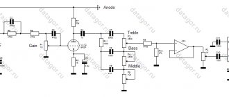
After reworking the Lunch box ear amplifier, a working prototype of the SRPP on the 6N23P remained. It was a shame to throw it away. There was a desire to finish the amplifier to the end. In the previous craft, we had to apply some simplifications related to the size of the case, for example: common power supply for both channels, not exactly the capacities that I would like to try. It was decided to make a new SRPP headphone amplifier on the 6N23P without these simplifications. The result was suddenly this kind of hybrid.
↑ My SRPP amplifier, uncompromising option
So, initially the idea was to make an ear SRPP with conditionally separate power supply of the channels (common transformer, bridge, inductor, then separate RC chains), with good capacitances, attractive, etc.
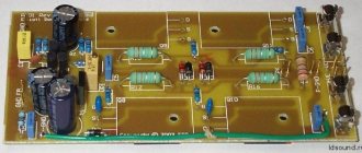
I decided to do everything on one board (see files). The principle is this: light bulbs and power capacitors up, everything else down. The board contained: a transformer, an electronic choke (as it turned out later, it was not in vain that I installed it). Next, the power is distributed by two different RC filters for each channel. There was also room for a volume control and a headphone jack. In the end it turned out like this:
The size of the board is 10x15 cm. The heat is supplied by twisted wires, packed in a screen and heat shrink. Signal wires: for each channel there are two MGTF cores (signal and ground) in the screen. The screen is connected to ground on one side (at the volume control).
A special feature of this design is the presence of expensive electrolytes from Jensen in the diet. I struggled with myself for quite a long time, but I still put it in. At first there were 2 of them (one per channel), but this design did not look very aesthetically pleasing. Somehow these capacitors stuck out lonely. Therefore, after another struggle with myself, I installed another common one, after the electronic throttle. It became prettier.
Bottom view of the board:
Another feature: good MKP Mundorf MCap-ZN capacitors in the power supply. Very useful for sound. Green wires with connectors appeared later. It has nothing to do with the headphone amplifier. In general, it turned out nice, just as I wanted. And it played well.
↑ Amplifier power supply
The power supply consists of a 160-watt transformer loaded onto a 25-amp rectifier bridge and provides a voltage of approx. 24 Volt. A U-shaped filter (capacitor - inductor - capacitor) is used, consisting of 10,000 Mf electrolytes and 5 Amp chokes with an inductance of 10 mH.
Rice. 3: Power supply diagram
Photo 2: Amplifier assembly
Photo 3: Amplifier assembly, rear view
↑ Idea about UMZCH
It's time to think about the body.
I almost always succeed: first the insides, and then the body around them. There were a lot of ideas, there was no hurry, I was thinking about it. As a result, an unexpected thought came to me: an ear amplifier is good, but maybe we can screw something to its output so that it can also drive the speakers if necessary? Were found, studied, thought about, etc. several options: from one transistor at the output, to splicing with microcircuit amplifiers such as TDA2050, LM3886, etc.
Two circuits were used in the prototypes: transistor final stages. One circuit is based on bipolar transistors, the second is based on field-effect transistors. After listening, I settled on field-effect transistors. I’ll tell you about it further.
Connection diagrams for field-effect and bipolar transistors
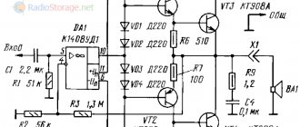
In Fig. 1 - 6 show circuit diagrams for connecting field-effect and bipolar transistors selected by practice, systematized in the collection of circuits by B.I. Goroshkova. They have a high input resistance, characteristic of field-effect transistors, and a low output resistance, characteristic of bipolar transistors.
Rice. 1. Connection diagram of field-effect and bipolar transistors.
Rice. 2. Connection diagram for field-effect and bipolar transistors - option 2.
The gain (transmission) of such cascades can be calculated using the formulas. In these formulas, Kui is the voltage gain of the cascade; h21e (or P) is the current transfer coefficient of the bipolar transistor; S - slope of the field-effect transistor characteristic (mA/V) RH - load resistance (kOhm).
Approximate, numerical values of h21e and S can be found in reference books or passport data; real values may differ markedly from the “theoretical” ones.
Rice. 3. Connection diagram for field-effect and bipolar transistors - option 3.
Rice. 4. Connection diagram for field-effect and bipolar transistors - option 4.
Rice. 5. Connection diagram for field-effect and bipolar transistors - option 5.
As follows from a comparison of formulas, amplification stages (Fig. 1, 3, 5, 6) have a gain (transmission) coefficient equal to the product of the individual transmission coefficients of the transistors included in the cascade. Cascades (Fig. 2, 4) have a transmission coefficient almost equal to unity.
Rice. 6. Connection diagram for field-effect and bipolar transistors - option 6.
Cascade (two, three or more “storey” connection of field-effect and/or bipolar transistors) allows by simple means to achieve a high transmission coefficient, reduce the penetration of the input signal to the amplifier output, simplify the circuit as a whole, increase the stability of its operation, increase the maximum value of the supply voltage and amplitude of the output signal, respectively.
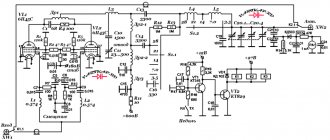
↑ Circuit with UMZCH on field-effect transistors
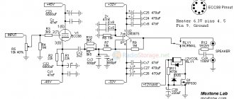
The diagram is taken as a basis from the site cxem.net. The final form of the diagram turned out like this:
The lamp used is 6N23P.
I also had to change the value of resistors R15 due to the fact that my supply voltage is lower than in the original circuit (±36V there) and without changing the value of the resistor it will not be possible to set the required quiescent current. After reading reviews about this circuit, I found out that there were complaints about the “crash” of the output transistors. Several assumptions about the reasons for this incident were voiced, but no consensus was reached. Despite the fact that nothing “crashed” for me, just in case I added protection: a circuit that shorted the gates to ground (via a resistor and a relay). The relay is normally closed and disconnects this grounding simultaneously with the connection of the speakers by the delay unit (after the lamps have warmed up and other transient processes when turned on). Those. when voltage is applied to the relay, the protection is turned off, and in the event of any unexpected events (for example, when the voltage to the relay is lost), the gates close to ground. I have 4 reed relays instead of one common one.
↑ Amplifier details
About the details used.
The transformers are toroidal. In SRPP there is a transformer with parameters: - 6.3V 1A - 170V 0.2A Rectifier diodes FR205. In the PA transformer: 2 windings of 20V 3A. There was no other. It is advisable to take a more powerful transformer. At maximum power the voltage drops slightly. The voltage can be increased further (I repeat, in the original source ±36V). Diode bridges D7 and D8 - which were available at 8A (KBU-8M). Radiators measuring 5x5x2 cm are installed on the bridges.
C6 - Jensen 500V 100 uF C10 - Jensen 500V 220 uF C5 - MKP Mundorf MCap-ZN 250V 2.2 uF C2 - ELNA Silmic II 10V 3300 uF C5 - ELNA Silmic II 250V 200 uF. I used two 100 uF connected in parallel. C1 and C4 - K73-17 C11, C12, C13 - 6.8 uF 250V of unknown brand (what happened). It’s better, of course, to install good capacitors; they greatly affect the sound. But these ones suited me too. I didn’t look for others or experiment. The remaining electrolytes are any, with suitable ratings. I have Epcos.
Zener diodes D10 and D12 - for voltage 12-15V. D11 and D13 – KD521.
If the STP9NK50Z transistor indicated in the diagram is used in the electronic choke, the D5.1 zener diode is not needed. Because it is already present in the transistor. The transistor in the electronic choke is located on a small radiator. Practically does not heat up.
Trimmer resistors R16 and R19 are multi-turn. Resistors R26 and R27 are assembled from three 2-watt, 1-ohm resistors connected in parallel. The remaining resistors are 0.25W ALPS volume control.
Anode voltage on the upper triode after RC circuits = 140V. You can adjust the anode voltage either with resistors (R7, R8) in the RC filter, or with the R9/R10 divider in the electronic choke.
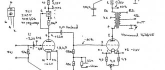
Power Supply Requirements
A simple mains power supply suitable for a class AB amplifier is shown in Fig. 6. Voltage ±30 V is taken from the secondary winding of the network transformer with a tap from the middle point. Noise suppression power supply decoupling capacitors C1 and C6 (Fig. 1) should be installed as close as possible to the output stage of the amplifier and serve to reduce power ripple to 5.5 V peak-to-peak at full load.
Rice. 5. Total nonlinear distortion factor of the amplifier.
Rice. 6. Simple network power supply for UMZCH, diagram.
↑ Layout
How to position the existing SRPP board and the new PA board in the case?
Standard option: flat case, boards in the same plane next to each other, radiators on the side or back. Not very original. If radiators are placed on top, then it is more original, but there is a danger of a short circuit due to power supply (on radiators, without insulating transistors, supply potential). Second option: boards on top of each other, radiators on the side. More original. Another advantage of this option is that in this case smaller body blanks are needed.
The second option is chosen. The amplifier board was wired the size of the SRPP board.
The board contains: the power supply, the amplifier itself and the speaker protection unit. A self-resetting 70 degree thermal fuse was subsequently attached to the transformer.
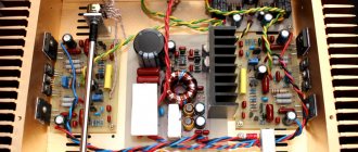
The output transistors, placed on the radiators through thermal paste, are connected to the board with wires soldered to the board's mounting terminals. On one side there are IRFP140. On the other hand, IRFP9140, i.e. the danger of accidental short circuit +/- 28V between each other is minimized. For additional safety, you can place the transistors on the radiators through a thermal pad. I did not specifically calculate the size of the radiators. I took the radiators that were the most suitable size from the nearest store “by eye”, based on experience. And in such a way that they do not protrude too much beyond the body (the dimensions of the body were already approximately clear). In the end, I was not mistaken. The heating of the radiator in the area where the transistors are mounted is about 60 degrees. Radiator dimensions: 8×15×3 cm
Transistor VT2 (thermal stabilizing) is located directly on the heatsink of one of the output transistors (on the reverse side) and is connected to the board using a connector, placed on the heatsink through a thermal pad.
Resistors R23 and R24 are not located on the board, but are soldered directly to the gates of the transistors.
The mounting terminals to which the wires of the output transistors are soldered are embedded in the board using the following technology: take a petal like this.
The tail bends at an angle of 90 degrees. A 3 mm hole is made on the board and a window is bored out with a needle file so that the tail fits into it. The result is something like this: The petal is inserted into the board from the track side. The tail passes through the board and sticks out from above (the wire is then soldered to it). The petal is screwed to the board with an M3 screw and additionally soldered around the edges.
The signal between SRPP and the PA is transmitted through the same “green wires” that were described above as “not related to the headphone amplifier.” On the SRPP board they are soldered, on the PA board they are connected through connectors.
The design in the form of a layout turned out like this:
A long time ago, two years ago, I purchased an old Soviet speaker 35GD-1. Despite its initial poor condition, I restored it, painted it a beautiful blue and even made a box for it out of plywood. A large box with two bass reflexes greatly improved its acoustic qualities. The only thing left is a good amplifier that will drive this speaker. I decided to do something different from what most people do - buy a ready-made class D amplifier from China and install it. I decided to make an amplifier myself, but not some generally accepted one on the TDA7294 chip, and not on a chip at all, and not even the legendary Lanzar, but a very rare amplifier on field-effect transistors. And there is very little information on the Internet about field amplifiers, so I became interested in what it is and how it sounds.
Assembly
This amplifier has 4 pairs of output transistors. 1 pair – 100 Watt of output power, 2 pairs – 200 Watt, 3 – 300 Watt and 4, respectively, 400 Watt. I don’t need all 400 watts yet, but I decided to install all 4 pairs in order to distribute the heating and reduce the power dissipated by each transistor.
The diagram looks like this:
The diagram shows exactly the values of the components that I have installed, the diagram has been tested and works properly. I have attached the printed circuit board. Lay6 format board.
Attention! All power paths must be tinned with a thick layer of solder, since a very large current will flow through them. We solder carefully, without snot, and wash off the flux. Power transistors must be installed on the heat sink. The advantage of this design is that the transistors do not need to be isolated from the radiator, but can be molded together. Agree, this saves a lot on mica heat-conducting spacers, because it would take 8 of them for 8 transistors (surprisingly, but true)! The heatsink is the common drain of all 8 transistors and the audio output of the amplifier, so when installing it in the case, do not forget to somehow isolate it from the case. Despite the fact that there is no need to install mica gaskets between the transistor flanges and the radiator, this place must be coated with thermal paste.
Attention! It’s better to check everything right away before installing the transistors on the radiator. If you screw the transistors to the heatsink, and there are any snot or unsoldered contacts on the board, it will be unpleasant to unscrew the transistors again and get smeared with thermal paste. So check everything at once.
Bipolar transistors: T1 – BD139, T2 – BD140. It also needs to be screwed to the radiator. They don't get very hot, but they still get hot. They also may not be isolated from heat sinks.
So, let's proceed directly to the assembly. The parts are located on the board as follows:
Now I am attaching photos of the different stages of assembling the amplifier. First, cut out a piece of PCB to fit the size of the board.
Then we put the image of the board on the PCB and drill holes for the radio components. Sand and degrease. We take a permanent marker, stock up on a fair amount of patience and draw paths (I don’t know how to do LUT, so I’m struggling).
Next, we throw the board into the ferric chloride solution and wait for it to do its job. Then we take it out, scrub the marker with a frying brush and the board is ready.
We arm ourselves with a soldering iron, take flux, solder and tin.
We wash off the remaining flux, take a multimeter and check for short circuits between tracks where there should not be one. If everything is normal, we proceed to installing the parts. Possible replacements. First of all I will attach the parts list: C1 = 1u C2, C3 = 820p C4, C5 = 470u C6, C7 = 1u C8, C9 = 1000u C10, C11 = 220n
D1, D2 = 15V D3, D4 = 1N4148
OP1 = KR54UD1A R1, R32 = 47k R2 = 1k R3 = 2k R4 = 2k R5 = 5k R6, R7 = 33 R8, R9 = 820 R10-R17 = 39 R18, R19 = 220 R20, R21 = 22k R22, R23 = 2.7 k R24-R31 = 0.22
T1 = BD139 T2 = BD140 T3 = IRFP9240 T4 = IRFP240 T5 = IRFP9240 T6 = IRFP240 T7 = IRFP9240 T8 = IRFP240 T9 = IRFP9240 T10 = IRFP240
The first thing you can do is replace the operational amplifier with any other one, even imported, with a similar pin arrangement. Capacitor C3 is needed to suppress the self-excitation of the amplifier. You can put more, which is what I did later. Any 15 V zener diodes with a power of 1 W or more. Resistors R22, R23 can be installed based on the calculation R=(Upit.-15)/Ist., where Upit. – supply voltage, Ist. – stabilization current of the zener diode. Resistors R2, R32 are responsible for the gain. With these ratings, it is somewhere around 30 - 33. Capacitors C8, C9 - filter capacitances - can be set from 560 to 2200 µF with a voltage not lower than Upit. * 1.2 so as not to operate them at their maximum capabilities. Transistors T1, T2 - any complementary pair of medium power, with a current of 1 A, for example our KT814-815, KT816-817 or imported BD136-135, BD138-137, 2SC4793-2SA1837. Source resistors R24-R31 can be set to 2 W, although it is undesirable, with a resistance from 0.1 to 0.33 ohms. It is not advisable to change power switches, although IRF640-IRF9640 or IRF630-IRF9630 are also possible; it is possible to use transistors with similar passing currents, gate capacitances and, of course, the same pin arrangement, although if you solder on wires, this does not matter. There seems to be nothing more to change here.
First launch and setup.
The first start-up of the amplifier is carried out through a safety lamp into a 220 V network break. Be sure to short-circuit the input to ground and do not connect the load. At the moment of switching on, the lamp should flash and go out, and go out completely: the spiral should not glow at all. Turn it on, hold it for 20 seconds, then turn it off. We check to see if anything is heating up (although if the lamp is not on, it is unlikely that anything is heating up). If nothing really heats up, turn it on again and measure the constant voltage at the output: it should be in the range of 50 - 70 mV. For example, I have 61.5 mV. If everything is within normal limits, connect the load, apply a signal to the input and listen to music. There should be no interference, extraneous hums, etc. If none of this is present, proceed to setup.
Setting up this whole thing is extremely simple. It is only necessary to set the quiescent current of the output transistors by rotating the trimmer resistor slider. It should be approximately 60 - 70 mA for each transistor. This is done in the same way as on Lanzar. The quiescent current is calculated using the formula I = Up./R, where Up. is the voltage drop across one of the resistors R24 - R31, and R is the resistance of this resistor. From this formula we derive the voltage drop across the resistor required to set such a quiescent current. Upd. = I*R. For example, in my case it = 0.07*0.22 = somewhere around 15 mV. The quiescent current is set on a “warm” amplifier, that is, the radiator must be warm, the amplifier must play for several minutes. The amplifier has warmed up, turn off the load, short-circuit the input to common, take a multimeter and carry out the previously described operation.
Characteristics and features:
Supply voltage – 30-80 V Operating temperature – up to 100-120 degrees. Load resistance – 2-8 Ohms Amplifier power – 400 W/4 Ohms THD – 0.02-0.04% at a power of 350-380 W Gain – 30-33 Frequency range – 5-100000 Hz
The last point is worth dwelling on in more detail. Using this amplifier with noisy tone blocks such as the TDA1524 may result in seemingly unreasonable power consumption by the amplifier. In fact, this amplifier reproduces interference frequencies that are inaudible to our ears. It may seem that this is self-excitation, but most likely it is just interference. Here it is worth distinguishing between interference that is not audible to the ear and real self-excitation. I encountered this problem myself. Initially, the TL071 opamp was used as a preamplifier. This is a very good high-frequency imported op-amp with a low-noise output using field-effect transistors. It can operate at frequencies up to 4 MHz - this is sufficient for reproducing interference frequencies and for self-excitation. What to do? One good person, many thanks to him, advised me to replace the opamp with another one, less sensitive and reproducing a smaller frequency range, which simply cannot operate at the self-excitation frequency. So I bought our domestic KR544UD1A, installed it and... nothing has changed. All this gave me the idea that the variable resistors of the tone unit were making noise. The resistor motors rustle a little, which causes interference. I removed the tone block and the noise disappeared. So it's not self-stimulation. With this amplifier you need to install a low-noise passive tone block and a transistor preamplifier in order to avoid the above.
Results
The result is a good amplifier that perfectly reproduces both low and high frequencies, heats up little and operates over a wide range of supply voltages. Personally, I really like the amplifier. All that remains is to build a pre-amplifier for it, a normal tone block and a housing, but more on that some other time.
Below I have attached several photos of the finished amplifier.
That's basically all. If you have any questions, ask them either on the VIP-CXEMA forum or by email to me. The email address is being protected from spambots. Javascript must be enabled in your browser to view the address.
Author: Dmitry4202
↑ A few words about switching
Firstly, the AC protection unit.
The protection unit had to satisfy the following requirements: — A delay when turning on was necessary, among other things, so that the lamps had time to warm up. — Protection against constant voltage at the output of both polarities. — Protection in case of loss of one of the supply voltage polarities. — Simplicity, no specialized microcircuits, only transistors and relays.
I tried several schemes. I haven't found the ideal. In the end, I left one, the best of them. But it’s not ideal either, so I don’t provide a diagram. I can't recommend it. For the same reason, the AC protection is not wired on the supplied board.
Secondly, nutrition.
In essence, you get two amplifiers in one housing. Each has its own power supply. I installed two toggle switches for 220V power supply. The first one includes SRPP itself and allows you to use the amplifier as an ear amplifier. It also supplies power to the second toggle switch. The second toggle switch supplies power to the power amplifier, allowing it to be turned on only when needed. The second groups of contacts of both toggle switches are connected in series and forcefully turn off the AC protection relay.
Thirdly, the AC Protection relay changes the contacts into 4 groups.
Two groups actually turn on the speakers, the third group supplies power to the gate protection relay. The fourth group of contacts switches the signal LED from red to yellow.
The result was the following operating logic:
— You can only turn on the headphone amplifier with the first toggle switch. If the second toggle switch is turned on, then the PA is turned on at the same time. Accordingly, without the first toggle switch, the PA does not turn on. — When the power amplifier is turned on (second toggle switch), the red LED lights up, there is a delay in turning on the speakers, the field gates are shorted to ground. — After a delay, the speakers are turned on, the protection relays are turned on and the gates are disconnected from the ground, the yellow LED turns on. — When the AC protection is triggered, the speakers are turned off, the red LED turns on and the gates are shorted to ground. — When the power is turned off by any of the toggle switches, the AC protection relay is forcibly turned off and, therefore, the AC is turned off and the gates are grounded.
In general, the protection turned out to be from all sides. No matter how you click the power switches, nothing bad will happen.
Cascade amplifiers with two field-effect transistors
"Double-deck" cascaded amplifiers require twice the supply voltage compared to conventional transistor switching, while the current consumed by the circuit is halved.
Rice. 7. Approximate equivalent of the K140UD7 microcircuit on two KP303 field-effect transistors.
In Fig. Figure 7 shows a circuit that allows you to simulate a rather complex internal structure analog microcircuit of the K140UD7 low-frequency amplifier [R 1/79-44].
Such a replacement, of course, should not be considered complete (especially in terms of gain). However, the use of a microcircuit equivalent made on discrete elements can be justified in some cases. Resistor R2 is selected until zero voltage is established at the output of the analogue microcircuit when the device is powered from a bipolar source.
↑ The amplifier case is made of “solid hevea”, hehe!
After listening to the model for a couple of weeks, my fears were confirmed: the transformer in the PA is noticeably heating up.
The 70 degree thermal fuse sometimes tripped. This means that forced ventilation must be provided. What is the body made of? By chance in the household department. of goods from one of the stores I saw these things:
Yes, these are cutting boards! As it was written: “hevea massif.” The size is suitable (20×30) and the price is affordable: 60 rubles each. a piece. I bought 8 pieces just in case. I went to a neighbor. His hobby is working with wood. And there is a suitable tool. They marked it, sawed it, made the necessary holes, glued it together, covered it with wax. It all took a couple of days of leisurely work. Thank him very much for his help. The result was a body like this:
Case size 27x18x15 cm.
↑ Assembling everything into the case
Insert the bottom PA board.
Radiators are mounted on the sides on yellow aluminum risers. At the rear there is a 220V fan measuring 80x80 mm at 1800 rpm with a roller bearing so that it does not make too much noise. The fan is turned on through a normally open thermal fuse at 60 degrees. Those. doesn't work all the time. The fuse is located on the side of the PA transformer farthest from the fan. In order to reduce vibration, the fan is not fixed in a standard way. The hole in the case for the fan is square. 3 – 4 mm wider on each side than the external dimensions of the fan. The fan is inserted inside the hole, the gaps are filled with silicone sealant (like plastic windows are filled with foam around them). After the sealant hardens, it holds tightly. The fan is covered from the outside with a decorative grille.
Hexagonal duralumin posts are screwed to the bottom board, on which the top SRPP board is placed.
Next are the racks again, to which the top cover is screwed.
It was not possible to get rid of the holes that were in the cutting boards. Didn't fit in size. I left them as ventilation. Subsequently, I covered them with metal mesh. I got the grids from this pencil cup:
The glass turned up in a store where “everything is sold at the same price.” In general, the nets were quite cheap.
The result was this original device:
↑ Listening
I listened to the finished version.
Plays loudly and not bad. I liked the sound. Drives modern speakers well. The scheme is omnivorous on columns. You can use 4 ohms or 8 ohms. To reinforce the positive impression, I took it to a neighbor who helped with the building. Here's a small digression. He listens to music on the following equipment: CD player, receiver, speakers. Everything is of good quality, famous brands. I will not indicate brands. It's not about the brand. When I heard all this being played a couple of years ago, I wasn’t afraid to say that there was something wrong with the sound. In principle, it’s normal, but everything doesn’t sound as we would like. There's some nonsense with tall people. And somehow blurred. In general, he agreed with me. They didn't look into it thoroughly. We agreed that most likely the speakers were let down.
In general, I brought this amplifier to him. We connected it to his speakers and turned it on. I had to take back my words about the speakers. The speakers turned out to be normal. Everything started to sound. There is practically nothing to complain about. After a couple of hours of listening, changing the repertoire, switching to vinyl and even a simple FM receiver, I got tired of looking for shortcomings. I left the amplifier for him to “drive and identify shortcomings” and left.
It took almost a month to “drive”. Other neighbors and guests took part in the process. There were no dissatisfied people. Looking ahead, I will say that my neighbor listened to many of the amplifiers I had assembled, and was so impressed by the good sound that I assembled a tube amplifier for him as a bonus. Now the “brand” is gathering dust. But that's another story.
Specifications
| Maximum RMS power | |
| at Rh = 4 Ohm, W | 60 |
| at Rh = 8 Ohm, W | 32 |
| Operating frequency range, Hz | 15…100 000 |
| Harmonic distortion factor: | |
| at f = 1 kHz, Pout = 60 W, Rh = 4 Ohm, % .. | 0,15 |
| at f = 1 kHz, Pout = 32 W, Rh = 8 Ohm, %. . | 0,08 |
| Gain, dB | 25…40 |
| Input impedance, kOhm | 47 |
↑ Conclusions
The sound is good.
For those who doubt their ability to build a complete tube amplifier, this design can be a worthy entry into tube sound. As an experiment, you can try an amplifier without cathode capacitors C1 and C2. Sounds different. I won’t undertake to compare the sounds; whoever likes it better. True, the gain will drop.
The maximum undistorted signal for the UMZCH turned out to be:
— at a load of 4 Ohms = 14V, i.e. 49 W, - at a load of 8 Ohms = 17V, i.e. 36 W. The input signal is about 1V. With a more powerful transformer in the PA, the output power will be higher. At least in the original source, at a supply voltage of ±36V, the power is 140 W.
The harmonics into a 4 ohm load look like this (power 10 W):
At 8 ohms the results are slightly better, but not fundamentally.
frequency response
The measurements were carried out on a load in the form of a 20W resistor at 4 Ohms.
↑ Editorial
• The amplifier's input sensitivity is low, about 2 Volts.
If you don't have such a source, then a preamplifier is a MUST. Any, with an output of 1-2 Volts. • Use sensitive 5-10 W speakers with lightweight (paper, fiber, etc.) diffusers, as for low-power tube amplifiers.
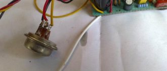
• The original 2SK1058 transistor is almost impossible to find these days. The Chinese now have offers for 2SK1058, but, as usual, there are no guarantees. You can get broken, re-marked, rejected or completely healthy. You can and should try, but at your own risk. Pay attention to the 2SK1058 case (see above in the article), it is very unique, some of the advertisements based on the photos can be immediately excluded.
Try different options
When comparing parameters in databoards, look for an available transistor with similar parameters. And even try just by ear. In the absence of 2SK1058, but with a strong desire, people assemble on unsuitable IRF530, IRF540, IRF610, etc.
Good luck everyone!
Igor
↑ Finishing
The audition was not in vain.
It turned out that periodically “the sound becomes louder and quieter.” Moreover, when it’s quieter, it sounds “better.” I took the amplifier back to look for the reasons for this behavior. It took me a long time to catch this effect. The first thing I did wrong was that the parameters went away when heated. Not confirmed. The quiescent current remained stable regardless of the temperature of the output transistors. The zero at the output also did not run away anywhere. It turned out that the mains voltage was to blame. Almost always it is stable 220V. Very rarely, that’s why I couldn’t catch it for a long time; it rose to 245 and even higher. In general, with increased voltage, the anode voltage also increased by 15-20 Volts. This was enough for the sound to change. This is where the fact that the SRPP power supply had an electronic choke came in handy. A couple of parts are mounted and it turns into a stabilizer. And everything fell into place. Note:
On the given board the choke is not routed in stabilizer mode.
At the moment, the amplifier has taken its place among other crafts. Periodically used when you need to arrange a “small disco”.