↑ Headphone amplifier circuit on TPA6120 and power supply
My version of the scheme
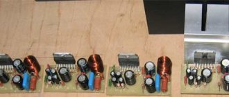
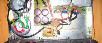
power unit
After studying the datasheet on the TPA6120, I still made some changes to the circuit. The so-called blocking capacitors in the original are film, but the datasheet strongly recommends using SMD ceramic capacitors, and even as close as possible to the power terminals - to eliminate possible excitation of the amplifier. As a matter of fact, I was most excited and afraid, the microcircuit is very fast-acting.
Let's finalize the scheme
The diagram presented in the document is somewhat incomplete. For normal operation, the circuit should be supplemented with input circuits.
Operational amplifiers are equally good at amplifying both AC and DC voltages. Therefore, despite all sorts of audiophile troubles, it is considered good form to add a capacitor to the input.
In addition to the capacitor that cuts off the DC voltage, you should add a resistor going to ground. Such a resistor will ensure that the non-inverting input of the op-amp is tied to ground. On the other side. together with the capacitor it forms an RC differentiating circuit.
The resulting RC circuit (R5, C1) will cut off both DC voltage and infra-low frequencies. They do not carry useful information, but they significantly load the amplifier with current. At the ratings indicated in the diagram, the cutoff frequency is 16 Hz. When using a 220nF capacitor, the cutoff frequency will drop to approximately 7Hz. Further increase in capacity does not make much sense.
To exclude possible self-excitation of the op-amp, it would not be amiss to limit the upper range. To do this, install a small capacitor in parallel with R2.
Circuit R2 C2 will act as a low pass filter. With the specified part ratings, the cutoff frequency will be about 100 kHz.
↑ This terrible PowerPAD is defeated
Due to the lack of experience in manufacturing double-sided PCBs, it was decided to make the board single-sided.
And then another problem emerged. Due to the fact that the microchip is very powerful for its size, it has a heat sink pad on its “belly” - PowerPAD, which is soldered to the pad under the microcircuit and also serves as a common wire. I somehow brushed aside the unpleasant thoughts and decided that I would solder it somehow. But first things first. I started looking for the necessary components, and it immediately became clear that the locals didn’t have the TPA6120, not to mention the ALPS. The Great Chinese Brother helps out once again, he ordered a TPA6120 chip and an ALPS potentiometer on Aliexpress. I bought the housing, transformer and other small items from the locals. After everything was in hand, another 4 months passed before I picked up... an iron.
When designing the amplifier board, I paid special attention to the location of the resistors in accordance with the datasheet, so that there were the shortest distances from the legs of the inputs and outputs to the resistors, so that there was no excitation. And now the boards are etched, drilled and tinned. And here I seriously began to think about how to solder this tricky PowerPAD and what to do with it in general.
Back on the Internet. I found an interesting solution on one of the forums. Without a soldering gun and double-sided PCB with metalized holes, there is only one way out: drill a hole under the microcircuit and through it try to solder a homemade radiator to the PowerPAD of the microcircuit.
I tried this suggested option:
a 1.5 mm hole is drilled, a copper wire is taken, tinned and wound in a spiral around a 0.8 mm drill (I wound it around a needle) 2-3 cm long. The microcircuit is positioned and grabbed, the spiral is lowered into the hole and the whole thing is fried with a 40-watt soldering iron , naturally with the addition of solder and flux. The goal is not just to solder the spiral, but also to ensure that the edges of the PowerPAD pad are also soldered to the printed circuit board.
Here it is, my cooling system for the TPA6120.
Do you see the strange “spring” in the center? I held the soldering iron for a few seconds and
it worked!
Everything turned out to be simpler than I thought. Thanks to the kind person for the idea!
Specifications
- Supply voltage: 3 - 12 V
- Power consumption: 10 mA / 3 V - 35 mA / 12 V (stereo)
- Output power: 300 mW
This headphone amplifier was built many years ago. And time has shown that this simple circuit is very reliable, it is difficult to burn, it has great power, excellent sound quality, consists of several simple parts and, importantly, consumes very little energy. With two AA batteries, the ULF can work for a very, very long time.
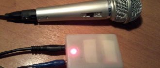
Such a convenient amplifier can find a variety of applications. For example, it can be used as a general purpose stereo amplifier for devices such as iPods, radios, CD players, computers, DVD players, televisions and so on. Or as an excellent audio amplifier for electric guitars, microphones, or as an audio tester.
The sound is really great and there is no shortage of bass. There is a mono version without a potentiometer. The goal was to get the smallest possible board without jumpers or SMD elements.
Transistor mono amplifier circuit
Despite its simple design, the amplifier behaves like a high-class pure transistor ULF. After a few minutes of playback, the details warm up and a little bass is added.
↑ Sound
The boards are ready, I connect everything with wires, quick check. There is no constant output, I connect my DAC, Senheisers, turn on “The Dark Side Of The Moon” and enjoy... Probably, describing the sound and especially its quality is a thankless task, you just have to hear it for yourself. In general, I will say that I really liked the sound throughout the entire frequency range. By ear there is a minimum of distortion, for me there is simply none. I used to listen to my Sennheiser HD 558 headphones with a built-in sound card. Now I simply didn’t recognize them! The bass appeared and the sound was very detailed.
A simple DIY headphone amplifier
If you have cool monitor ears and an old mobile phone with an MP3 player that is not able to “pump up” the headphones, then this article is for you!
Minimum set:
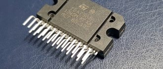
- The TDA 2822 micra itself (you can also modify it 2822 M/S or its analogue KA 2209)
- 4 electrolytic capacitors 16V - 100 mF (well, in general, capacitors are like butter in porridge - bigger is better, but for headphones 100 mF is an excellent size/quality ratio)
- Wiring is lighter, multi-colored 20-25 cm is enough for the head.
- Soldering iron and everything for soldering
- straight hands and a sober head are welcome????
↑ Total
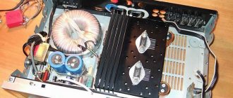
Us is singing. There is no excitement, and thank God, fortunately, all measures were taken for this. I doubted that the coil would dissipate heat well, so I left it for an hour with music at a decent volume, touched the microcoil - it felt like 30-35 degrees. The coil is warm, the pad on the reverse side is also slightly warm, which means the microcoil is soldered normally, the heat is dissipated well, and that’s where I calmed down.
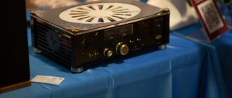
And the most difficult and painful thing for me began - to collect everything into the case. A couple of evenings with a drill, pliers, screwdrivers, files and a lot of obscene language! Hurray, I stuffed the boards into the case. The case turned out to be too big for the amplifier, but it is convenient to mount and looks more solid in a large box. There is only one task left: to make inscriptions on the front panel. But that's a completely different story.
Vol.X - DIY Portable Headphone Amplifier
Unfortunately, not everyone understands why you need a camera when you have a telephone. And even fewer people understand why a headphone amplifier is needed. We will not just look at why it is needed, but we will also assemble an inexpensive and high-quality portable headphone amplifier. So simple that anyone can do it...
Vol.X Headphone Amplifier - An attempt to write an article in real time as the project progresses. Comments are welcome!
Follow the progress on Twitter.
As the project progresses, the article will be supplemented with the necessary material. The ultimate goal is to create a complete, easy to replicate, high quality portable headphone amplifier design. The emphasis is on the possibility of implementing an amplifier by a person who does not have deep knowledge of electronics.
If you understand the beauty of pictures floating around the Internet, then you can assemble an amplifier :-).
Why is the amplifier called Vol.X? -Don't know. It was simply decided to give a specific name to this project. Sounds more solid. Maybe in time it will come to Vol.X2. Who knows…
Creation
- OA = OPA2134
- VD1 = red LED 1.7 volts
- VT1 = MPS2907A ~= KT361
- VT2 = IRF610
- VT3 = IRF9620 or IRF9510
- VD2, VD3 = stable at 9…15 V
- C1 = 1uF (audiophile quality)
- RP1 = 100 KOhm
- R1, R3 = 1 KOhm
- R2 = 100 KOhm
- R4 = 2 KOhm
- R5, R6 = 3 KOhm
- R7 = 360 Ohm (*)
- R8, R9 = 100 Ohm
- R10, R11 = 3.3 Ohm 1 Watt
- C2…C7 = 0.1 µF (film)
- C8, C9 >= 4700 µF x 35 V
- C10 = 47uF x 16V (aluminum)
The bias voltage on the follower gates (drop across R5) is set using the same current source, which helps the operational amplifier operate without switching distortion. It is advisable to provide a through current through the output transistors of the order of 100 mA. To do this, you may have to pick up R7.
First - the word
In my audio designs, I try to avoid negative feedback loops in general. But everything has its time and place. This article is more a tribute to common sense than to my maximalist aspirations.
We take a high-quality operational amplifier and make it work in an honest class “A”. To do this, we load the output of the opamp to the current source. The idea appears to be Walt Jung's and was first used in the Philips DAC960 in the nineties. Even if audio historians are wrong, this idea still works well. This can be seen clearly, in pictures, in my article about the generator on the Wien Bridge.
Since a small op-amp cannot be loaded with 30-ohm headphones, we need a current amplifier. In this case, a push-pull source follower based on unpretentious MOSFET (MDS) transistors from International Rectifier. When operating on a relatively high-resistance load, the repeater does not leave pure class “A”.