One of the developments - the TDA1514A
- can help even beginning radio amateurs create a Hi-Fi amplifier, since it does not require any trimming elements or preliminary selection of transistors, and its connection circuit is only slightly more complicated than a conventional operational amplifier.
I will list the advantages of the TDA1514 chip:
— reasonable price — high power, up to 50 Watts! — low distortion — thermal protection — no click when turning on/off
I can say, perhaps, she sings really well. Or rather, she sang... That’s probably why they stopped releasing it. Marketing, damn it. Seize the moment, take it if you can find it. Outgoing nature...
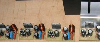
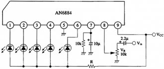
↑ Addition from Alexander Vorobyov, dual-channel board
The design itself is assembled on two identical microcircuits and is a 2-channel (stereo) amplifier with an output power of 100 Watts (2×50W). The input signal is fed to a low-high pass filter formed by R1(R9), C1(C11), R2(R9), C2(C12) and then to the 1st leg of the microcircuit. It is not worth abandoning these filter chains, since frequencies below 20 Hz and above 30 kHz, mainly interference signals and intermodulation frequency components, can significantly spoil the sound picture.
The gain of the cascade is set by the ratio of resistors R5(R13)/R3(R11) and for this circuit is equal to 30. The chain R6(R14), R7(R15), C4(C15) is called a “voltage booster” and serves to power the pre-terminal stage of the microcircuit with increased voltage . This allows you to increase the output power of the amplifier as a whole by 10%-20%. According to popular opinion, it somewhat worsens the dynamic characteristics, so for those who like to experiment, it is quite possible to exclude chains R7 (R15), C4 (C15) from the circuit, and install wire jumpers instead of R6 (R14). Without any harm to the microcircuit.
Capacitors C3 (C6), C5 (C13), C9, C10 are necessary to eliminate the inductive component of power circuits and serve to eliminate excitation of the amplifier at frequencies above the audio range. The R8(R16), C8(C16) chain also plays a similar role. The output windings of the power transformer and rectifier diodes, not indicated in the diagram, must provide a current of 3A at an alternating voltage of 18V - 22V. It is very convenient to use a transformer from old TS180 TVs for this. The network winding is left unchanged, and instead of the other windings, a new one is wound, with a wire with a diameter of at least 1 mm.
High quality 50W amplifier based on TDA1514A chip
In this article I will tell you about a microcircuit such as TDA1514A
Introduction
Let me start with something sad... At the moment, production of the microcircuit has been discontinued... But this does not mean that it is now “worth its weight in gold”, no. You can get it in almost any radio store or radio market for 100 - 500 rubles. Agree, a little expensive, but the price is absolutely fair! By the way, on global Internet sites such as eBay and Aliexpress they are much cheaper...
The microcircuit is characterized by a low level of distortion and a wide range of reproduced frequencies, so it is better to use it on full-range speakers. People who have assembled amplifiers using this chip praise it for its high sound quality. This is one of the few microcircuits that truly “sounds well.” The sound quality is in no way inferior to the currently popular TDA7293/94. However, if errors are made in the assembly, high-quality work is not guaranteed.
Brief description and advantages
This chip is a single-channel Hi-Fi amplifier of class AB, the power of which is 50W. The chip has built-in SOAR protection, thermal protection (overheating protection) and “Mute” mode
The advantages include the absence of clicks when turning on and off, the presence of protection, low harmonic and intermodulation distortion, low thermal resistance, and more. There is practically nothing to highlight among the shortcomings, except failure when the voltage “runs” (the power supply must be more or less stable) and the relatively high price
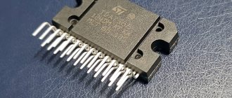
Briefly about appearance
The chip is available in a SIP package with 9 long legs. The pitch of the legs is 2.54mm. On the front side there are inscriptions and a logo, and on the back there is a heat sink - it is connected to the 4th leg, and the 4th leg is the “-” power supply. There are 2 eyelets on the sides for attaching the radiator.
The original or a fake?
Many people ask this question, I will try to answer you.
So. The microcircuit must be carefully made, the legs must be smooth, minor deformation is allowed, since it is unknown how they were handled in a warehouse or store
The inscription... It can be made either with white paint or with a regular laser, the two microcircuits above are for comparison (both are original). If the inscription is painted, there should ALWAYS be a vertical stripe on the chip, separated by an eyelet. Don’t be confused by the inscription “TAIWAN” - it’s okay, the sound quality of such copies is no worse than the ones without this inscription. By the way, almost half of the radio components are made in Taiwan and neighboring countries. This inscription is not found on all microcircuits.
I also advise you to pay attention to the second line. If it contains only numbers (there should be 5 of them) - these are “old” production microcircuits. The inscription on them is wider, and the heat sink may also have a different shape. If the inscription on the microcircuit is applied with a laser and the second line contains only 5 digits, there must be a vertical stripe on the microcircuit
The logo on the microcircuit must be present and only “PHILIPS”! As far as I know, production ceased long before NXP was founded, and this is 2006. If you come across this microcircuit with the NXP logo, then one of two things is happening - they started producing the microcircuit again or it’s a typical “leftist”
It is also necessary to have depressions in the shape of circles, as in the photo. If they are not there, it is a fake.
Perhaps there are still ways to identify the “leftist”, but you shouldn’t stress over this issue so much. There are only a few cases of marriage.
Technical characteristics of the microcircuit
| Parameter | Magnitude | Meaning | ||
| min. | nom. | Max. | ||
| Supply voltage | IN | ±8 | — | ±30 |
| Quiescent current (at ±27.5V) | mA | — | 56 | — |
| Gain* | dB | 29 | 30 | 31 |
| Frequency range | Hz | 20 — 25000 | ||
| Consumption current | A | — | — | 8 |
| Input impedance* | mOhm | 1 | — | — |
* Input impedance and gain are adjusted by external elements
Below is a table of approximate output powers depending on power supply and load resistance
| Supply voltage | Load resistance | ||
| 4 ohm | 8 ohm | ||
| +-12V | 10W | 6W | |
| +-16.5V | 28W | 12W | |
| +-23V | 48W | 28W | |
| +-25V | 58W | 32W | |
| +-27.5V | 69W | 40W | |
Schematic diagram
The diagram is taken from the datasheet (May 1992)
It's too bulky... I had to redraw it:
The circuit differs slightly from that provided by the manufacturer; all the characteristics given above are exactly for THIS circuit. There are several differences and they are all aimed at improving the sound - first of all, filter capacitors were installed, the “voltage boost” was removed (more on that a little later) and the value of resistor R6 was changed.
Now in more detail about each component. C1 is the input coupling capacitor. It passes through only the alternating voltage signal. It also affects the frequency response - the smaller the capacitance, the smaller the bass and, accordingly, the larger the capacitance, the greater the bass. I would not recommend setting it to more than 4.7 µF, since the manufacturer has provided for everything - with the capacitance of this capacitor equal to 1 µF, the amplifier reproduces the declared frequencies. Use a film capacitor, in extreme cases an electrolytic one (non-polar is desirable), but not a ceramic one! R1 reduces the input resistance, and together with C2 forms a filter against input noise.
As with any operational amplifier, the gain can be set here. This is done using R2 and R7. At these ratings, the gain is 30 dB (may deviate slightly). C4 affects the activation of SOAR and Mute protection, R5 affects the smooth charging and discharging of the capacitor, and therefore there are no clicks when the amplifier is turned on and off. C5 and R6 form the so-called Zobel chain. Its task is to prevent the amplifier from self-excitation, as well as to stabilize the frequency response. C6-C10 suppress power supply ripples and protect against voltage sags. The resistors in this circuit can be taken with any power, for example I use the standard 0.25W. Capacitors for a voltage of at least 35V, except for C10 - I use 100V in my circuit, although 63V should be enough. All components must be checked for serviceability before soldering!
Amplifier circuit with “voltage boost”
This version of the circuit is taken from the datasheet. It differs from the above-described scheme in the presence of elements C3, R3 and R4. This option will allow you to get up to 4W more than stated (at ±23V). But with this inclusion, distortion may increase slightly. Resistors R3 and R4 should be used at 0.25W. I couldn’t handle it at 0.125W. Capacitor C3 - 35V and above.
Bridge circuit
This circuit requires the use of two microcircuits. One gives a positive signal at the output, the other a negative one. With this connection, you can remove more than 100W into 8 ohms.
According to those who gathered, this scheme is absolutely workable and I even have a more detailed table of approximate output powers. It's below:
| Supply voltage, V | Output power, W | Load resistance, Ohm |
| ±15 | 55 | 4 |
| ±20 | 65 | 8 |
| ±23 | 100 | 8 |
| ±27 | 70 | 16 |
And if you experiment, for example, at ±23V you connect a 4 ohm load, you can get up to 200W! Provided that the radiators do not heat up too much, the 150W microcircuit will be easily pulled into the bridge.
This design is good to use in subwoofers.
Operation with external output transistors
The microcircuit is essentially a powerful operational amplifier and it can be further boosted by adding a pair of complementary transistors to the output. This option has not yet been tested, but it is theoretically possible. You can also power up the bridge circuit of the amplifier by attaching a pair of complementary transistors to the output of each microcircuit
Operation with unipolar power supply
At the very beginning of the datasheet, I found lines that say that the microcircuit also works with single-supply power. Where is the diagram then? Alas, it’s not in the datasheet, I couldn’t find it on the Internet... I don’t know, maybe such a circuit exists somewhere, but I haven’t seen one... The only thing I can recommend is TDA1512 or TDA1520. The sound is excellent, but they are powered from a single-polar supply, and the output capacitor can slightly spoil the picture. Finding them is quite problematic; they were produced a very long time ago and were discontinued a long time ago. The inscriptions on them can be of various shapes; there is no need to check them for “fake” - there have been no cases of refusal.
Both microcircuits are Hi-Fi class AB amplifiers. Power is about 20W at +33V into a 4 ohm load. I won’t give the diagrams (the topic is still about the TDA1514A). You can download printed circuit boards for them at the end of the article.
Nutrition
For stable operation of the microcircuit, you need a power source with a voltage from ±8 to ±30V with a current of at least 1.5A. The power should be supplied with thick wires, the input wires should be kept as far away from the output wires and the power source. You can power it with an ordinary simple power supply, which includes a mains transformer, a diode bridge, filter capacitors and, if desired, chokes. To obtain ±24V, you need a transformer with two 18V secondary windings with a current of more than 1.5A for one microcircuit.
You can use switching power supplies, for example the simplest one, on IR2153. Here is his diagram:
Here you need to calculate the transformer to suit your needs. This can be done in the ExcellentIT program from the user Starichok
This UPS is made using a half-bridge circuit, frequency 47 kHz (set using R4 and C4). Diodes VD3-VD6 ultrafast or Schottky
It is possible to use this amplifier in a car using a boost converter. On the same IR2153, here is the diagram:
The converter is made according to the Push-Pull scheme. Frequency 47kHz. Rectifier diodes need ultrafast or Schottky ones. Transformer calculations can also be performed in ExcellentIT. The chokes in both schemes will be “recommended” by ExcellentIT itself. You need to count them in the Drossel program. The author of the program is the same - Starichok
I would like to say a few words about the IR2153 - the power supplies and converters are quite good, but the microcircuit does not provide stabilization of the output voltage and therefore it will change depending on the supply voltage, and it will also sag.
It is not necessary to use IR2153 or switching power supplies in general. You can do it simpler - like in the old days, a regular transformer with a diode bridge and huge power supply capacities. This is what its diagram looks like:
C1 and C4 at least 4700 µF, for a voltage of at least 35V. C2 and C3 - ceramics or film.
Printed circuit boards
Now I have the following collection of boards: a) the main one - it can be seen in the photo below. b) slightly modified first (main). All tracks have been increased in width, the power ones are much wider, the elements have been slightly moved. c) bridge circuit. The board is not drawn very well, but it is functional d) the first version of the PCB is the first trial version, there is not enough Zobel circuit, but I assembled it this way and it works. There is even a photo (below) d) printed circuit board from XandR_man - found on the forum of the Soldering Iron site. What can I say... Strictly a diagram from the datasheet. Moreover, I saw with my own eyes sets based on this signet! In addition, you can draw the board yourself if you are not satisfied with the ones provided.
Soldering
After you have made the board and checked all the parts for serviceability, you can start soldering. Tin the entire board, and tin the power traces with as thick a layer of solder as possible. First, all the jumpers are soldered in (their thickness should be as large as possible in the power sections), and then all the components increase in size. The microcircuit is soldered last. I advise you not to cut the legs, but solder them as they are. You can then bend it to make it easier to fit on the radiator.
The microcircuit is protected from static electricity, so you can solder with the soldering iron turned on, even while sitting in woolen clothes.
However, it is necessary to solder so that the chip does not overheat. For reliability, you can attach it to the radiator by one eye during soldering. You can do it in two, there won’t be any difference, as long as the crystal inside doesn’t overheat.
Setup and first launch
After all the elements and wires are soldered, a “test run” is necessary. Screw the microcircuit onto the radiator and connect the input wire to ground. You can connect future speakers as a load, but in general, to prevent them from “flying out” in a split second due to defects or installation errors, use a powerful resistor as a load. If it crashes, you know that you made a mistake, or you got a defect (the microcircuit is meant). Fortunately, such cases almost never happen, unlike TDA7293 and others, of which you can get a bunch of them in a store from one batch and, as it turns out later, they are all defective.
However, I want to make a small note. Keep your wires as short as possible. It happened that I just lengthened the output wires and began to hear a hum in the speakers, similar to “constant”. Moreover, when the amplifier was turned on, due to the “constant” mode, the speaker produced a hum that disappeared after 1-2 seconds. Now I have wires coming out of the board, a maximum of 25 cm, and they go straight to the speaker - the amplifier turns on silently and works without problems! Also pay attention to the input wires - use a shielded wire; you shouldn’t make it long either. Follow simple requirements and you will succeed!
If nothing happened to the resistor, turn off the power, attach the input wires to the signal source, connect your speakers and apply power. You can hear a slight hum in the speakers - this indicates that the amplifier is working! Give a signal and enjoy the sound (if everything is perfectly assembled). If it “grunts” or “farts” - look at the nutrition, at the correctness of assembly, because as has been discovered in practice, there are no such “disgusting” specimens that, with proper assembly and excellent nutrition, worked crookedly...
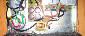
What the finished amplifier looks like
Here is a series of photographs taken in December 2012. The boards are just after soldering. Then I assembled it to make sure the microcircuits were working.
But my first amplifier, only the board has survived to this day, all the parts went to other circuits, and the microcircuit itself failed due to alternating voltage coming into contact with it
Below are the latest photos:
Unfortunately, my UPS is at the manufacturing stage, and I previously powered the microcircuit from two identical batteries and a small transformer with a diode bridge and small power supply capacities, in the end it was ±25V. Two such microcircuits with four speakers from a musical device played so well that even the objects on the tables “danced to the music”, the windows rang, and the power was felt quite well in the body. I can’t remove this now, but there is a ±16V power supply, from it you can get up to 20W at 4 ohms... Here is a video for you as proof that the amplifier is absolutely working!
Acknowledgments
I express my deep gratitude to the users of the Soldering Iron site forum, and specifically, many thanks to the user VINS2009 for some help, I also thank DTS, Andrey 69, KRAB and many others (sorry for not calling you by nickname) for honest reviews that pushed me to build this amplifier Without all of you, this article might not have been written.
Completion
The microcircuit has a number of advantages, first of all, excellent sound. Many microcircuits of this class may even be inferior in sound quality, but this depends on the quality of the assembly. Bad assembly means bad sound. Take electronic circuit assembly seriously. I strongly do not recommend soldering this amplifier by surface mounting - this can only worsen the sound, or lead to self-excitation, and subsequently complete failure.
I collected almost all the information that I checked myself and could ask other people who assembled this amplifier. It's a pity that I don't have an oscilloscope - without it, my statements about the sound quality mean nothing... But I will continue to say that it sounds just great! Those who collected this amplifier will understand me!
If you have any questions, write to me on the forum of the Soldering Iron site. There is a separate topic here to discuss amplifiers on this chip, you can ask there.
I hope the article was useful to you. Good luck to you! Regards, Yuri.
List of radioelements
| Designation | Type | Denomination | Quantity | Note | Shop | My notepad |
| Chip | TDA1514A | 1 | Search in the Otron store | To notepad | ||
| C1 | Capacitor | 1 µF | 1 | Search in the Otron store | To notepad | |
| C2 | Capacitor | 220 pF | 1 | Search in the Otron store | To notepad | |
| C4 | Electrolytic capacitor | 3.3uF | 1 | Search in the Otron store | To notepad | |
| C5 | Capacitor | 22 nF | 1 | Search in the Otron store | To notepad | |
| C6, C8 | Electrolytic capacitor | 1000uF | 2 | Search in the Otron store | To notepad | |
| S7, S9 | Capacitor | 470 nF | 2 | Search in the Otron store | To notepad | |
| C10 | Electrolytic capacitor | 100uF | 1 | 100V | Search in the Otron store | To notepad |
| R1 | Resistor | 20 kOhm | 1 | Search in the Otron store | To notepad | |
| R2 | Resistor | 680 Ohm | 1 | Search in the Otron store | To notepad | |
| R5 | Resistor | 470 kOhm | 1 | Search in the Otron store | To notepad | |
| R6 | Resistor | 10 ohm | 1 | Selected during setup | Search in the Otron store | To notepad |
| R7 | Resistor | 22 kOhm | 1 | Search in the Otron store | To notepad | |
| Circuit with voltage boost | ||||||
| Chip | TDA1514A | 1 | Search in the Otron store | To notepad | ||
| C1 | Capacitor | 1 µF | 1 | Search in the Otron store | To notepad | |
| C2 | Capacitor | 220 pF | 1 | Search in the Otron store | To notepad | |
| C3 | Electrolytic capacitor | 220uF | 1 | From 35V and above | Search in the Otron store | To notepad |
| C4 | Electrolytic capacitor | 3.3uF | 1 | Search in the Otron store | To notepad | |
| C5 | Capacitor | 22 nF | 1 | Search in the Otron store | To notepad | |
| C6, C8 | Electrolytic capacitor | 1000uF | 2 | Search in the Otron store | To notepad | |
| S7, S9 | Capacitor | 470 nF | 2 | Search in the Otron store | To notepad | |
| C10 | Electrolytic capacitor | 100uF | 1 | 100V | Search in the Otron store | To notepad |
| R1 | Resistor | 20 kOhm | 1 | Search in the Otron store | To notepad | |
| R2 | Resistor | 680 Ohm | 1 | Search in the Otron store | To notepad | |
| R3 | Resistor | 47 Ohm | 1 | Selected during setup | Search in the Otron store | To notepad |
| R4 | Resistor | 82 Ohm | 1 | Selected during setup | Search in the Otron store | To notepad |
| R5 | Resistor | 470 kOhm | 1 | Search in the Otron store | To notepad | |
| R6 | Resistor | 10 ohm | 1 | Selected during setup | Search in the Otron store | To notepad |
| R7 | Resistor | 22 kOhm | 1 | Search in the Otron store | To notepad | |
| Bridge connection | ||||||
| Chip | TDA1514A | 2 | Search in the Otron store | To notepad | ||
| C1 | Capacitor | 1 µF | 1 | Search in the Otron store | To notepad | |
| C2 | Capacitor | 220 pF | 1 | Search in the Otron store | To notepad | |
| C4 | Electrolytic capacitor | 3.3uF | 1 | Search in the Otron store | To notepad | |
| C5, C14, C16 | Capacitor | 22 nF | 3 | Search in the Otron store | To notepad | |
| C6, C8 | Electrolytic capacitor | 1000uF | 2 | Search in the Otron store | To notepad | |
| S7, S9 | Capacitor | 470 nF | 2 | Search in the Otron store | To notepad | |
| C13, C15 | Electrolytic capacitor | 3.3uF | 2 | Search in the Otron store | To notepad | |
| R1, R7 | Resistor | 20 kOhm | 2 | Search in the Otron store | To notepad | |
| R2, R8 | Resistor | 680 Ohm | 2 | Search in the Otron store | To notepad | |
| R5, R9 | Resistor | 470 kOhm | 2 | Search in the Otron store | To notepad | |
| R6, R10 | Resistor | 10 ohm | 2 | Selected during setup | Search in the Otron store | To notepad |
| R11 | Resistor | 1.3 kOhm | 1 | Search in the Otron store | To notepad | |
| R12, R13 | Resistor | 22 kOhm | 2 | Search in the Otron store | To notepad | |
| Impulse power block | ||||||
| IC1 | Power Driver and MOSFET | IR2153 | 1 | Search in the Otron store | To notepad | |
| VT1, VT2 | MOSFET transistor | IRF740 | 2 | Search in the Otron store | To notepad | |
| VD1, VD2 | Rectifier diode | SF18 | 2 | Search in the Otron store | To notepad | |
| VD3-VD6 | Diode | Any Schottky | 4 | Ultrafast diodes or Schottky | Search in the Otron store | To notepad |
| VDS1 | Diode bridge | 1 | Diode bridge for the required current | Search in the Otron store | To notepad | |
| C1, C2 | Electrolytic capacitor | 680uF | 2 | 200V | Search in the Otron store | To notepad |
| C3 | Capacitor | 10 nF | 1 | 400V | Search in the Otron store | To notepad |
| C4 | Capacitor | 1000 pF | 1 | Search in the Otron store | To notepad | |
| C5 | Electrolytic capacitor | 100uF | 1 | Search in the Otron store | To notepad | |
| C6 | Capacitor | 470 nF | 1 | Search in the Otron store | To notepad | |
| C7 | Capacitor | 1 nF | 1 | Search in the Otron store | To notepad | |
| S8, S10 | Electrolytic capacitor | 1000uF | 2 | Search in the Otron store | To notepad | |
| C9, C11, C20 | Capacitor | 100 nF | 3 | Search in the Otron store | To notepad | |
| R2, R3 | Resistor | 100 kOhm | 1 | 0.5W | Search in the Otron store | To notepad |
| R4 | Resistor | 14 kOhm | 1 | Search in the Otron store | To notepad | |
| R5, R6 | Resistor | 27 Ohm | 2 | Search in the Otron store | To notepad | |
| R8 | Resistor | 1 kOhm | 1 | 2W | Search in the Otron store | To notepad |
| R9 | Resistor | 47 kOhm | 1 | 2W | Search in the Otron store | To notepad |
| Tr1 | Transformer | 1 | TVS-110Pts15 | Search in the Otron store | To notepad | |
| L1-L4 | Inductor | 100µH | 4 | Search in the Otron store | To notepad | |
| F1 | Fuse | 10A | 1 | Search in the Otron store | To notepad | |
| Powering the amplifier in the car | ||||||
| IC1 | Power Driver and MOSFET | IR2153 | 1 | Search in the Otron store | To notepad | |
| VT1, VT2 | MOSFET transistor | IRF3205 | 2 | Search in the Otron store | To notepad | |
| VD3-VD6 | Diode | 4 | Ultrafast or Schottky | Search in the Otron store | To notepad | |
| C4 | Capacitor | 1000 pF | 1 | Search in the Otron store | To notepad | |
| C5 | Electrolytic capacitor | 100uF | 1 | Search in the Otron store | To notepad | |
| C6 | Capacitor | 470 nF | 1 | Search in the Otron store | To notepad | |
| S8, S10 | Electrolytic capacitor | 1000uF | 2 | Search in the Otron store | To notepad | |
| C9, C11 | Capacitor | 100 nF | 2 | Search in the Otron store | To notepad | |
| R4 | Resistor | 14 kOhm | 1 | Search in the Otron store | To notepad | |
| R5, R6 | Resistor | 27 Ohm | 2 | Search in the Otron store | To notepad | |
| Tr1 | Transformer | 1 | Mounted on a ferrite ring M2000HM 31x19x7 | Search in the Otron store | To notepad | |
| L3, L4 | Inductor | 100µH | 2 | Search in the Otron store | To notepad | |
| Transformer power supply | ||||||
| Tr1 | Transformer | 1 | Transformer for the required voltage | Search in the Otron store | To notepad | |
| VDS1 | Diode bridge | 1 | For the required voltage and current | Search in the Otron store | To notepad | |
| C1, C4 | Electrolytic capacitor | 4700uF | 2 | Not less than 4700uF 35V | Search in the Otron store | To notepad |
| C2, C3 | Capacitor | 100 nF | 2 | Film or ceramic | Search in the Otron store | To notepad |
| Add all | ||||||
Attached files:
- tda_pp.rar (94 Kb)
Tags:
- ULF
- Sprint-Layout
↑ Board option in “Sprint Layout” from BLACK EAGLE
In the archive there are connection diagrams and a drawing of the PP in Layout: