Today you can see how developers of various computer equipment, in particular laptops, are increasingly trying to move away from the use of old USB drives in their devices, which have been replaced by Type-C connectors. As an example, you can look at the 12-inch MacBook or the latest MacBook Pro. These devices do not have standard USB drives, so for these purposes you will need a USB converter, which we will talk about later.
Need to purchase
You can find USB converters in a wide variety of variations, which differ not only in shape, but also in the number, as well as the types of connectors available. If it happens that this device is still necessary, then you should not rush headlong into buying the most “sophisticated” one - proceed from your needs.
Well, to make it easier for you to understand which USB converter is best for you and what approximate price it will cost you, for this case below we have prepared a list of current USB adapters that can be easily found in any digital equipment store.
Toslink or SPDIF coaxial to L/R RCA audio converter
Good afternoon, ladies and gentlemen! Today I would like to gladly show you a very unusual thing, namely a subject!
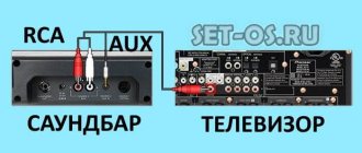
Actually, the purchase was not spontaneous, not so long ago a new TV was purchased, on which there is no analogue audio output as a class, only coaxial and optics. By the way, many years ago, my good friends gave me acoustics, which I am completely satisfied with (well, it’s clear that only within the framework of my bearish ear for music).
Anyone who is interested in the idea of pairing these devices - here's the cut!
Actually, the idea was born to cross these two devices so that the latter would cease to be a dust collector and start working for its intended purpose.
After a short search, a suitable adapter was found.
It didn’t take long... as always - about three weeks, unfortunately the packaging was not preserved, but it was packaged badly - just a yellow bag, inside a box containing:
The adapter itself
Power supply with non-Orthodox plug
Some meaningless instructions and that's all.
I would like to note that there was no European adapter included in the kit, but this is not the seller’s fault - he kindly inquired about the desired adapter, but I, being on vacation, could not answer him, and he did not bother much. Who needs it, write it yourself. And I took mine out from the storerooms. No problem.
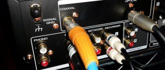
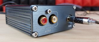
Let's get down to business! The adapter is assembled very high quality: the plastic is good quality, there are no snot or assembly jambs
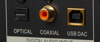
On one side of this device there are: Power connector, Power indicator (not visible when turned off), Inputs: Coaxial, Optics
On the other hand Outputs: Jack 3.5 and RCA
Let's put it all together: I don't understand what kind of optics for 200 rubles. offline:
But why don't you understand? understand! - full of feces! Okay, it works =)
We connect the speakers, power supply - the red LED on the device lights up - everything seems to be ready to start.
Turn on the sound source:
I can only test it on online radio and TV.
Everything started up, the acoustics began to sing. The sound was pleasantly surprising, even I, being absolutely indiscriminate in sound quality, note that the old speaker began to sing in new colors... although this may be a placebo.
For lovers of dismemberment:
The soldering is neat - no faults, the microcircuit markings have been filed off, but the name shows through (I was never able to identify it)
Conclusions: The device is definitely worth the money, I bought it for the money, there are cheaper ones, there are more expensive ones, but for what I bought it, it does an excellent job. I was afraid that there would be a lag in the sound, but there is none, TV looks without problems, there is no delay.
Pros: + Price + Build quality + No lag + Sound quality
Cons: - Unknown controller - No on/off button
To buy or not - the choice is yours. I just tried to tell you about what I bought myself. Thank you for your attention!
There are no kittens, there is a dog:
Like this:
USB-C Multiport Digital AV Adapter
A little more complex in its design is an adapter that supports the HDMI interface and two connectors for standard USB. On the other hand, we still have the same Type-C connector.
The wider design prevents this adapter from being used in tight spaces, but you will now be able to output images via HDMI.
In terms of price, such a device will cost you approximately 6,000 rubles.
Universal Hub USB Type-C
If you are looking for something more sophisticated and powerful, then you should pay attention to special “boxes” with a set of ports for various interfaces.
In the screenshot below you see the Chinese universal Hub from Baseus, which has connectors for USB 3.0, HDMI and Type-C.
There are options with a card reader for reading data from SD cards. This is the QacQoc GN21B adapter, which connects directly to a laptop and turns one Type-C port into 5 new ports that differ from each other.
You can easily find such devices on AliExpress, and their price varies from 2000 to 3800 rubles.
Add a link to a discussion of the article on the forum
RadioKot >Schemes >Digital devices >PC gadgets >
| Article tags: | Add a tag |
USB to RS-232 converters
Author: Aheir, DeNew Published 11/12/2007
We continue the conversation about the USB bus and its use in amateur radio practice.
Last time (USB 1.1 hub Light version) we quite successfully equipped the PC with a dozen additional USB ports, now it’s time to start using all this abundance.
Naturally, the first thing that comes to mind is to use these ports to exchange data with your own designs on the MK. However, not all microcontrollers now have peripherals for working directly with USB, and the software implementation of this protocol is quite complex and takes up a lot of processor time. On the other hand, the vast majority of microcontrollers have on board a universal asynchronous transceiver module that can operate in a mode compatible with the RS-232 protocol, i.e. Such a microcontroller, provided the signal levels are matched, can be connected directly to the COM port of the computer. What does USB have to do with it, you ask? I’ll answer: manufacturers, as always, made a fuss, as a result of which several options for USBRS-232 interface converters appeared on the market. Those. We have at our disposal a device that connects to a PC via USB, and the output has signals that are understandable to any MK with a USART module (or even with a software-implemented USART). Great? Of course, it’s great, especially considering that the OS perceives such an adapter as just another (virtual) COM port (VCP: Virtual Com Port) and allows you to work with it using ordinary terminal tools.
Today we will talk about microcircuits that allow us to implement all this...
Perhaps the most common today are the FT232BM converters from FTDI Ltd (USB 1.1) (doesn’t the name remind you of anything from Maxim? ), TUSB3410 from Texas Instruments (USB 2.0), as well as PL-2303 from Prolific. What kind of animals are these? We'll figure out…
The FT232BM is available in a 32-lead LQFP-32 package with 0.8mm pin pitch.
The microcircuit has an interface for connecting external EEPROM memory (pins 1, 2 and 32), which can store unique identification codes of the manufacturer and device type, as well as text strings containing information about the name, manufacturer of the device, etc. The microcircuit can be powered either from the USB bus or from an external stabilized power source with a voltage of 5V. A 6MHz quartz is used as a clock generator, connected to pins 27 and 28.
The microcircuit has a built-in LDO stabilizer with an output voltage of 3.3V, which serves to power the internal logic, but can also be used to power any external devices (pin 6: 3V3OUT), however, the maximum current is only 5mA. The logic one level at the outputs of the UART module of the microcircuit (pins 16-25) is set by the voltage at the VCCIO input (pin 13) and can vary from 3 to 5V (this is necessary to ensure compatibility with 3-volt logic).
The power mode of the microcircuit is determined by the logical level at the PWRCTL input: logic 0 – power from the USB bus (Bus-Powered), logic 1 – power from a third-party source (Self-Powered). The inverse RESET input must be connected through a resistor (or even without it) to the positive power supply of the microcircuit - this is enough for normal operation. The RSROUT output can be used to reset external devices when the FT232 is reset. In addition, a pull-up resistor for the USB Data+ line is connected to this pin. The Data+ and Data- lines themselves are USBDP and USBDM pins, respectively.
I note that the TEST input must be connected to ground, otherwise the operation of the microcircuit is unstable.
The SLEEP and PWREN outputs can be used to control external devices, in particular, SLEEP = 0 if the microcircuit is not active (“sleeping”), and PWREN = 0 after initialization of the microcircuit is completed when connected and = 1 if the microcircuit is not active.
At pins 16-25, as already noted, all signals provided for by the RS-232 standard are present. By connecting the appropriate level converter chips to them, it is possible to convert the source data received via USB into a byte stream of RS-232, RS-422 or RS-485 protocols.
USB data reception and transmission can be indicated by LEDs connected to the RXLED and TXLED outputs respectively.
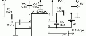
The diagram I usually use is shown in the figure:
As you can see, there are very few hanging elements. To connect to the MK, it is enough to use the RX and TX signals; in some cases it may be necessary to organize galvanic isolation of this circuit from the rest of the device. Taking into account the fact that the converter is powered by USB, it is enough to add an optocoupler to RX and TX, and the TX output can directly control the LED of one of the optocouplers.
As EEPROM, you can use 93C46/56/66 memory chips, even the smallest in volume is enough:
We figured out the hardware a little, but as for the software, there’s nothing complicated here either. Two versions of the driver are available for download from the manufacturer’s website: VCP Driver (virtual COM port driver only) and D2XX Driver (provides a number of additional features, for example, direct access to USB - more interesting for programmers). If you plan to use a memory chip, you need to install D2XX; in addition, you will also need a special utility for firmware: MProg, also available for download from the website. For the rest, connect the device to the PC, tell the OS where to get the drivers from, and monitor the installation. In the “Device Manager” in the “USB” section “USB Serial Converter” should appear, and in “Ports” the next numbered “USB Serial Port” should appear. That's it, you can work with it as with a regular port.
This will happen if your FT232 works without EEPROM (or with an empty one) with standard VID&PID assigned by the manufacturer. If you use MProg to flash new VID&PID, device name, serial number, etc. into memory, your device will be detected completely differently. How – you know better, there is room for creativity. Although I still wouldn’t recommend changing the standard VID&PID, otherwise you’ll end up with some kind of scanner...
I worked with this chip at a port speed of 115200, although the driver allows you to set the maximum speed up to 921600. In the “Port Settings” section of the port properties there is an “Advanced” button. There, in the “BM Options” section, the “Latency Timer” parameter should be set to a lower value, i.e. 1ms – this will increase the speed.
If you are seriously planning to use this microcircuit, I advise you to read the materials on the page, there is actually a lot of useful and interesting information there, and many points are explained in much more detail than in this article.
With TUSB3410 everything will be a little more complicated. The fact is that this chip is essentially a microcontroller with an integrated USB interface module. Therefore, like any microcontroller, it will also have to be programmed...
It so happened that this microcircuit is produced in the same package:
The functionality is approximately the same: a full serial port (pins 13-21, only RX/TX are called SIN/SOUT), an interface for EEPROM (here it is I2C), crystal, power, Reset and four programmable general purpose I/O lines P3. 0 – P3.4 – the FTDI definitely didn’t have them... The supply voltage of the microcircuit is 3.3V, which is not very convenient, since when powered from USB it forces the use of an LDO stabilizer. But there are no tricky diets.
Well, as always, let’s briefly go over the functional purpose of the conclusions? Go…
Everything seems to be clear with the serial port, I’ll just say that with the appropriate firmware it can work not only via the RS-232 protocol, but also as an IrDA transceiver. Four I/O lines are also not exotic; the manufacturer, in particular, provides an example where they are used to connect several buttons, and the device is defined by the OS as HID-compatible, which makes it quite easy to implement polling of these same buttons.
DP, DM – Data+ and Data- USB lines, PUR is used to connect a pull-up resistor for the Data+ line.
The VDD18 line must be supplied with a voltage of 1.8V from an external source or, what is simpler, a logic 0 must be applied to the VREGEN pin, thereby turning on the internal 1.8V source, and a 0.1uF capacitor must be added to VDD18 to ground...
For RESET, a regular RC chain is more than enough, TEST0 and TEST1 need to be connected via 10 kOhm to the power supply, and we will not use the CLKOUT clock output.
12 MHz quartz on legs X1 and X2, SUSPEND indicator output - to taste, WAKEUP wake-up input can be left unconnected or pulled up through a resistor to the power supply positive.
You can also directly connect MCUs, optocouplers or level converters to the serial port lines of this microcircuit.
It seems that everything necessary for the minimal configuration was connected, the diagram turned out like this:
The EEPROM chip is also not a mandatory element here and I personally have never used it...
So, we assembled this circuit, plugged it into the computer, the OS found a certain device and asked us to poke our nose into the drivers for it. This is where the fun begins.
As I already said, TUSB3410 is actually a microcontroller, inside it is an 8052-compatible core. Accordingly, the functionality of our device is determined by the installed firmware. For now, we need an interface converter.
In principle, subject to registration and provision of information about your project, the manufacturer provides both the source code and the firmware for using the microcircuit as an interface converter, but you can go the other way. This microcircuit is used in this capacity in some interface cords for mobile phones, in GSM modems, and in some other devices. And drivers for them are available for free download. Moreover, all these drivers contain the necessary firmware. This is due to the operating features of the microcircuit.
The fact is that when installing the driver, the firmware for the microcontroller is copied to /System32/drivers. Next, when you turn on the device, TUSB checks for the presence of EEPROM and firmware in it. If everything is in order, it boots from it; if not, it loads the firmware from the computer and writes it to the EEPROM, if it exists. Or it doesn’t record and just works. If there is no EEPROM, the next time you turn on the process repeats.
In general, as a result of analyzing several sets of drivers for ready-made devices using trial and error, successive approximations and highly scientific poking, our own working set was generated. All driver files and even inside the firmware contain Texas Instruments copyrights, so I will say that all actions taken on the drivers were intended exclusively for educational and non-commercial purposes, and here the result is published purely for informational purposes.
After connecting to the PC, the OS will find a new device “TUSB3410 Device” and require driver installation; you must point to the umpusbXP.inf file. During installation, the umpusbxp.sys and umpf3410.i51 (firmware) files will be copied to the system directory. Next, the system will find a virtual COM port; it will require the UmpComXP.inf driver.
In both *.inf files, lines are marked, by changing which you can edit the names of system-defined devices and default VID&PIDs transmitted by the OS. However, just like last time, I wouldn't do this without fully understanding what it might lead to.
Why TUSB3410 needs EEPROM I have already mentioned. I’ll add that I personally haven’t experimented with it, but on the manufacturer’s website there is a utility available for download for generating a binary EEPROM firmware file based on umpf3410.i51 and a configuration file (contains the device serial number, VID&PID, string data similar to the FT232BM) and a utility for Direct firmware of the received file into the microcircuit.
On the page dedicated to this microcircuit, if desired, you can find a detailed datasheet, a number of appnotes, documents describing the application features, links to source codes and utilities for work. I highly recommend watching it.
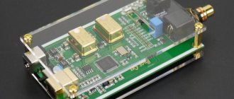
The result of all this research was the creation of two modules for converting the USB protocol to RS-232, on FT232BM and TUSB3410, respectively, which can be seen in the photograph:
The installation, as you can see, is superficial, all the parts are on one side, and on the inside there are a couple of jumpers. The modules are designed for vertical soldering into the board, so they do not have connectors, but PLS pins are installed, which are actually soldered into the board. On the side of the board farthest from us, RX/TX pads are made (on the FT232BM module they are blocked by a capacitor), the remaining serial interface signals are not output as unnecessary: these modules are used exclusively for interfacing with the MK.
Returning a little to the FT232BM. Below you can see a photo (and at the end of the article - download board layout options) for two designs on the FT232BM with a full RS-232 port. In the first of them
RS-232 signals have a TTL level and are output to a double-row BH-10 connector (by analogy with motherboards), and by switching the VCCIO input (pin 13) to 5V or a third-party 3.3V source (in this case an LDO stabilizer is used, but you can , for example, and use parametric or adjustable on LM317) using a jumper you can select the appropriate level of logical “1” at the pins of the RS-232 port. This design was developed for debugging devices with a supply voltage of 3.3V
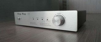
Another version of the module with a full RS-232 port contains the MAX213 chip - a level converter - and thus provides compatibility with PC serial ports in terms of voltage levels. The module diagram is shown in the figure:
And the finished device looks like this:
Now about the PL-2303: the chip is available in a 28-pin SSOP package with a pin pitch of 0.65mm:
The chip is similar in many ways to the FT232, but also has some features of the TUSB3410. Operation requires a 12 MHz quartz resonator (pins 27-28), the logical unit level of the serial port is determined by the voltage at the input VDD_232 (4), pins 1-3, 5, 6 and 9-11 are a full serial port. By analogy with TUSB3410, the microcircuit has a pair of pins (13-14) for connecting EEPROM via I2C (the memory is also used to store device identifiers). Input 23 determines the current load mode of the USB port (“1” - 500mA, “0” - 100mA), the TRI-STATE input determines the state of the serial port outputs when the microcircuit is initialized: “1” - high level, “0” - high impedance state. Separate power inputs for logic (8, 20) and PLL (24) can generally be connected to the USB power bus, but it is advisable to place ceramic capacitors to ground in close proximity to them. The PL-2303 has a built-in 3.3V voltage source to power the USB transceiver (pin 17), which is also used to install a pull-up resistor to the Data+ line. As usual, for a more complete, accurate and correct description, you should visit the manufacturer’s website. The diagram of the module developed on the basis of this microcircuit is shown in the figure:
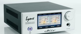
Photos of the finished device:
As you can see, this module also contains the MAX213 (SP213) chip, and therefore provides support for a full-featured RS-232 port, level-compatible with PC ports. For full operation of this device running Windows OS, you will need drivers available for download on the manufacturer’s website. Since these chips make quite a lot of interface cords for connecting mobile phones to PCs, it is likely that drivers from them will also work.
As usual, we put the questions here.
Files:
FT232BM module (SL5 format) FT232BM + EEPROM module (SL5 format) FT232BM + EEPROM module with 3.3V interface and full RS-232 port (SL5) FT232BM + EEPROM module with full RS-232 and MAX213 (SL5 board and SPlan circuit) Module TUSB3410 (SL5 format) TUSB3410 driver (WinXP) Circuit and board for PL-2303 (SL5)
| What do you think of this article? | Did this device work for you? | |
| 74 | 1 | 0 |
| 0 | 0 |