Scheme of a simple homemade short-wave (HF) converter for receiving broadcast stations on a receiver with a CB (MW) band. Nowadays, most audio equipment is equipped with a VHF-FM (FM) receiving path. A smaller portion is AM and FM, with “AM” usually being medium wave (MW or MW).
Less commonly, there are two AM bands - NE and LW (MW and LW). And very rarely, along with NE and LW, the short-wave range (SW) is also present. But the fact of the matter is that in recent years there has been absolutely nothing to do in the NE (MW) and Far East (LW). Only at night on NE (MW) you can receive a few long-distance radio stations. At the same time, radio broadcasting on HF (SW) is not particularly reduced.
But the most interesting thing is that the specificity of the propagation of radio waves in the shortwave range is such that, thanks to multiple tropospheric reflection, it is possible to receive very long-distance radio stations on a very mediocre receiving device.
You can receive radio stations from a variety of countries, in a variety of languages, which is especially useful for people learning foreign languages, because listening to the radio in the language you are studying can be very effective in practicing both pronunciation and translation.
In my opinion, it’s completely in vain that the industry pays so little attention to the short-wave range, and it’s time to release equipment with “FM / SW” bands. But nonetheless. However, converting any AM receiver or receiving path with the CB (MW) band to receiving short waves is not so difficult.
It is necessary to connect an additional frequency converter between the antenna and the antenna input, a converter that will receive HF (SW) radio stations and transfer them to the SW (MW) band, where they can then be listened to using a receiver with the SW (MW) band.
Schematic diagram
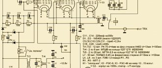
This topic has already been widely studied by radio amateurs and there are many descriptions of KB converter circuits in the literature. Without pretending to be original, I will give a diagram (Fig. 1) of a KB converter that I have been using for several years. The scheme is very simple and does not require any setup at all.
The desire to completely abandon the need for adjustment required abandoning the input circuit. This, of course, to a certain extent affected the selectivity in the mirror channel, but reception remained possible.
For example, when using a quartz resonator with a frequency of 8.86 MHz from video equipment, it becomes possible to receive in two sub-bands at once, in the lower, within 7.3-8.3 MHz, and in the upper, within 9.4-10.5 MHz, which covers the range “31 meters” and partly the “41 meters” range.
Rice. 1. Schematic diagram of a homemade HF converter based on the SA612A chip (resistor R1 - 510 Ohm).
Battery HF receiver 0-V-1
You can receive shortwave amateur radio stations using a simple tube receiver (for example, a 0-V-1 type receiver).
Below we describe a similar two-tube receiver operating on 2K2M tubes, having a detector stage with feedback and a low-frequency amplification stage.
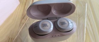
The receiver covers a wave range from 9 to 160 m using five interchangeable coils. The receiver circuit is shown in Fig. 2.
Rice. 2. Schematic diagram of the shortwave receiver 0-V-1.
All parts of the receiver, with the exception of the loop coils and capacitor C4, are factory. The receiving capacitor C3 can be of any type with a maximum capacity of 100-125 µmF.
Resistance R7 is variable with a maximum value of 75,000-100,000 ohms. Resistance R10 extinguishing excess, glow battery voltage, wire, 8-10 ohms. The remaining resistances are TO type.
Permanent capacitors can be used of any type. Receiver coils for the 160, 80, 20 and 14 g ranges are wound on pressed frames with a diameter of 35 g, and for the 10 g range on a frame with a diameter of 18 mm. The coil data is given in table. 2.
Table 2.
| L1 | L2 | L3 | ||||
| Ranges, m | number of turns | wire diameter, mm | number of turns | wire diameter, mm | number of turns | wire diameter, mm |
| 10-14 | 2 | 1 | 3,5 | 1 | 5 | 0,3 |
| 20 | 3 | 1 | 7 | 0,8 | 5 | 0,3 |
| 40 | 3 | 1 | 12 | 0,8 | 6 | 0,3 |
| 80 | 5 | 1 | 21 | 0,4 | 9 | 0,2 |
| 160 | 8 | 0,5 | 65 | 0,2 | 20 | 0,2 |
The coil frames are mounted on blanks with a diameter of 38 mm or on sockets from lamps of the 4-volt series (SO-118, SB-155, etc.). Coils L1, L2 and L3 are wound on one frame at a distance of 0.8-1.0 cm from each other. L2 coils for 160 and 40 m are wound turn to turn, and for other ranges with a forced step of 1 mm turn from turn.
L1 coils for all ranges are wound with a forced pitch of 1 mm. To connect the required coil to the receiver, a five-pin lamp socket is installed on the receiver chassis.
Variable capacitor C4 consists of one movable and one fixed aluminum plate. The design of the capacitor is clear from Fig. 3. The receiver is mounted on a wooden chassis measuring 160X 150X50 mm.
The front panel can be made of 4-5-gauge plywood, the inside of which should be covered with aluminum foil (from broken paper microfarad capacitors). It will be very good if it is made of 1.5-2 lg aluminum.
Front panel size 160 X 160 l. Capacitors C3 and C4, variable resistance R7 and switch Vk are mounted on it. The horizontal panel houses lamp sockets and sockets for switching on the coils.
Setting up a receiver primarily comes down to obtaining smooth generation on all bands. This is achieved by changing the distance between the coils L2 and L3, as well as selecting the capacitance of the capacitor C5 and the resistance R1.
If generation does not occur, then you need to change the ends of the Li coil or reduce the capacitance of capacitor C2. The next step in setting up a receiver is to determine the boundaries of the amateur bands.
Fig. 3. Design of a homemade variable capacitor.
1-front wall of the chassis; 2-plug socket; 3- pin from the plug; 4-gaskets. 5 - movable plate; 6-fixed plate; 7- terminals of the capacitor.
To power the receiver, you need to have an anode battery with a voltage of 120-140V and a 2V incandescent battery. As an anode battery, it is best to take two BAS-80 or BS-70 batteries connected in series.
To power the incandescent lamps, you can use two elements of the type BNS-MVD-100 or BNS-MVD-500 connected in series.
Excess voltage is extinguished by resistance R10. When the battery voltage decreases after prolonged operation, resistance R10 turns off.
Details
Of course, there is a nuisance in the fact that both ranges simultaneously appear on the same scale, but, nevertheless, reception is possible and with very good quality.
Although, of course, you can install an input circuit or even two input circuits, one at “31 meters”, the other at “41 meters” and switch them. But this will require adjustment and adjustment of these circuits to these frequencies, which will significantly complicate the manufacture of such a converter at home.
Other quartz resonators can be used. It is important to know that a receiver with a CB (MW) band covers the range 0.52 - 1.6 MHz. And the broadcasting sections of the KB band are located as follows:
- 90 meters - 3.2 - 3.4 MHz.
- 75 meters - 3.9-4.0 MHz.
- 60 meters - 4.75 - 5.06 MHz.
- 49 meters - 5.9-6.2 MHz.
- 41 meters - 7.1 - 7.4 MHz.
- 31 meters - 9.5 - 9.9 MHz.
- 25 meters - 11.65 - 12.06 MHz.
- 22 meters - 13.6 -13.8 MHz.
- 19 meters - 15.1 -15.6 MHz.
- 16 meters - 17.55 -17.9 MHz.
- 13 meters - 21.45 - 21.85 MHz.
- 11 meters - 25.65-26.1 MHz.
To understand what range will be accepted when using a specific quartz resonator, you need to add or subtract the frequency of the MF (MW) range from its resonant frequency. That is, to determine the lower limit, add (subtract) 0.52 MHz, and to determine the upper limit, add (subtract) 1.6 MHz.
HF Upconverter - Listen to the HF band on an SDR whistle for $7
We are talking about a fairly specific device. There hasn’t been anything similar to mysku yet, so maybe it will be useful for someone, and someone might even find a new hobby for themselves, and the open-frame design directly hints at complete DIY operation. The device under review is a frequency converter and is used to transfer HF bands to VHF so that SDR receivers, which many are already familiar with (times two), can hear the air below 25 MHz.
And below 25 MHz there is a large world of exotic broadcast radio stations and radio amateurs, which, due to their use of single sideband modulation, simply cannot be heard on a household receiver. And the combination of upconverter + SDR whistle for $7 will probably be the most budget solution for this. Not counting the very collective farm options with direct sampling and soldering the antenna directly to the chip.
What you can hear on HF:
-Broadcasting stations from different parts of the world -Radio amateurs -Radio pirates Where to find them all:
Broadcast radio stations here and here. AM modulation
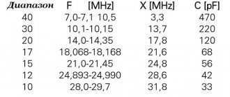
Radio amateurs 160 meters (1.81 - 2 MHz), 80 meters (3.5 - 3.8 MHz), 40 meters (7 - 7.1 MHz), 30 meters (only telegraph 10.1 - 10 .15 MHz), 20 meters (14 - 14.35 MHz), 16 meters (18.068 - 18.318 MHz), 15 meters (21 - 21.45 MHz), 12 meters (24.89 - 25.14 MHz), 10-meter (28 - 29.7 MHz).
Radio amateurs usually use different modulations from broadcast stations. from 160 meters to 40 meters it is LSB (lower sideband) from 20 meters and above USB (upper sideband). This is for voice conversations. There is also CW - telegraph, and many digital types of communication that can squeeze out a stingy tear from someone who experienced modem communication 20 years ago. The communication speed is usually around 2400 baud. All this is transmitted in open form, so everything that is transmitted can be viewed using special tools. programs. For example fldigi.
Radio pirates are the same radio amateurs only outside the law. Popular frequencies are 6660 kHz and 10460 kHz.
It should be noted that for high-quality HF reception, an antenna somewhat larger than a meter telescopic antenna is highly desirable. Ideally, you need to use either a wire several tens of meters long or a magnetic antenna, which is much more compact and noise-resistant, but requires constant adjustment and is somewhat more difficult to manufacture. Industrial versions of magnetic antennas are unforgivably expensive. Probably due to individual production in small batches.
Now let's move on to the device itself.
It arrived in a regular postal bag with a bubble wrap, inside of which there was an antistatic bag with a converter.
The device itself. It is developed within the framework of the openhardware concept and has exhaustively open documentation right down to the board layout. Therefore, the Chinese, without further ado, simply copied everything one after another and the output was exactly what the developers intended. It’s true that the developers already have a newer version of the converter available - 1.3, but the changes there are minor, and the price and paid delivery from them makes the new version not so attractive. Also, the Chinese version, unlike the official one, has a fully wired white noise generator.
To power the converter, 5 volts are required, which are supplied via the USB-B connector. There are no laces included. The antenna connectors are made of common SMA connectors. The board also has an operating mode switch that turns off the converter and turns on the antenna directly for working with VHF.
The principle of operation of the converter is quite simple. The operating frequency range is separated from the input signal by filters, after which it is mixed by an ADE-1 mixer with a reference frequency of 125 MHz obtained from a quartz resonator, filtered again, and sent to the SDR receiver. That is, the original signal received by the antenna at a frequency of 14 MHz, after passing through the converter, will be received by the SDR receiver at a frequency of 139 MHz. In order to avoid confusion, all popular SDR software has a frequency shift function, where it is necessary to specify -125 MHz in this case to work with current frequencies.
Signal operations are not without losses. On one mixer alone they reach 5 dB. The total losses in the device reach 10 dB, so it’s difficult to call all this an ultra-sensitive receiver in its original design, but this is probably the only more or less significant drawback. The developers of the device justify the absence of an additional amplifier by the fact that in their minds it should be located directly next to the antenna. And in general they are right. But as practice has shown, even without an additional amplifier the device works more than well. However, the input signal is still quite weak, so for comfortable work with the converter it is necessary to enable signal amplification in the SDR receiver itself using the appropriate checkboxes and sliders in the program.
The first versions of this device used a 100 MHz quartz resonator, which created a lot of additional interference due to the presence in cities of a large number of FM stations, which are mostly located at frequencies of 100+ MHz. This specimen has quartz at 125 MHz, and it is at this frequency that it shifts the HF range up. Although frequencies of 125+ MHz are actively used in aviation, due to the low signal power they do not create noticeable interference, perhaps only near airfields and air traffic control centers.
Finally, a short video demonstrating how the converter works. I don’t have a normal HF antenna yet, and I recorded it while going to a barbecue with radio amateurs. A transceiver is working nearby and when it switches on to transmit, all its harmonics are clearly visible, as well as the wild overload of the receiver. But this allows us to evaluate its sensitivity for long-distance correspondents in comparison with a transceiver whose price is a couple of thousand dollars. It is clearly visible that not all correspondents can be heard on the SDR, but given the lack of an antenna amplifier in the SDR and the constant overloads, the result seems to me to be very decent. The Poles, for example, could be heard very well.
As a result, we have a budget device that copes well with its functions. I can only list one drawback so far - the inconvenient USB-B power connector. As for the rest, with the right approach, it will allow you to get a good set for an HF receiver for $50, which can easily give a head start to receivers twice as expensive as an SDR set, and with an additional antenna amplifier it can compete with its more expensive counterparts. Not to mention the advantages of SDR in visualization, ease of setup, and subsequent signal processing.
Anticipating questions about the correct approach, I will mention the lack of quartz in cheap SDR whistles, which do not have high frequency stability and “float” depending on temperature. In the near future, I will try to describe here the improvements to the SDR receiver itself, replacing the quartz with a thermally stable one. Obtained from Ali, of course.