HF converters for amateur radio
This article provides diagrams of converters for amateur radio HF bands. The shortwave converter diagram is shown in Fig. 1 . Designed to work in conjunction with a radio receiver having a medium-wave broadcast range. The converter is made on one K217 microcircuit, which includes four transistors of the n – p – n structure. It is designed for reception in the amateur bands 10 m (28 ... 29.7 MHz), 14 m (21 ... 21.45 MHz), 20 m (14 ... 14.350 MHz), 40 m (7 ... 7.1 MHz), and also broadcast stations in the ranges of 25 m (11.7 ... 11.97 MHz), and 31 m (9.5 ... 9.7 MHz). Reception is carried out using an indoor or outdoor antenna. They are tuned to radio stations using the receiver's variable capacitor.
In the position of the contacts of switch S1 antenna WA1 is connected to socket X1.2 connected to the antenna input of the radio receiver. No power is supplied to the converter. To turn on the converter , press switch button S1 . Its group of contacts S1.1 connects the antenna through capacitor C1 to the contact groups of switches S2 - S7 , which switch the input circuits of the converter. At the same time, group of contacts S1.2 supplies power to the converter, and group S1.3 turns on the indicator - LED VD3. For example, the 10 m range is selected and the switch button S2 . Then circuit L1C15 will be connected to the antenna, the signal from which is supplied through capacitor C4 to the base of transistor VT2, which operates as a mixer. At the same time, circuit L8C21 will be connected to transistors VT3, VT4 of the local oscillator through capacitor C8. The high-frequency voltage of the local oscillator through the coupling coil L7 and capacitor C7 enters the emitter circuit of the mixer transistor. The intermediate frequency signal (it is chosen in this case to be about 1 MHz) is fed to the input of the broadcast receiver. The converter works similarly when pressing switch buttons for other ranges. The diodes VD1 and VD2 installed at the converter input protect it and the broadcast receiver from failure when high amplitude signals are received from the antenna. The converter is powered by a DC source with a voltage of 9 ... 12 V. The voltage supplied to the mixer and intermediate frequency amplifier is stabilized by a parametric stabilizer VD4. The voltage to the local oscillator is supplied from another stabilizer, assembled on a zener diode VD3. The design uses P2K switches ( S1 – with independent, and S2 – with dependent fixation). The coils are wound on frames with an outer diameter of 4 mm, a height of 10 mm with a trimmer made of carbonyl iron from armored magnetic cores SB-12a. For the coils of the input circuits, PEV-1 0.2 wire is used. Coil L1 contains 11 turns with tapping from the 3rd turn, counting from the bottom according to the output circuit; L2 – 12.5 turns with a tap also from the 3rd turn; L3 – 14.5 turns with a tap from the 4th turn; L4 – 17.6 with a tap from the 4th turn; L5 and L6 - 20.7 turns each with a tap from the 6th turn. The local oscillator coils are wound with PELSHO wire 0.15, and the communication coils PEV-1 0.2. Coil 10.5 turns, L10 - 12, L12 - 14.2, L14 - 17, L16 and L18 - 19.3 turns each. All communication coils must contain 3 turns. The microcircuit can be replaced with four KT312B transistors or similar ones. Setting up the converter begins with checking the operating modes of the transistors indicated on the diagram. The band switch buttons are not pressed yet. Then they check the operation of the local oscillator by connecting an oscilloscope (through a capacitor with a capacity of approximately 1000 pF) to the collector of the VT4 transistor. Rectangular pulses should be observed on the oscilloscope screen. If they are missing, resistor R8 should be selected. Next, press the button of any range switch - high-frequency sinusoidal oscillations should appear on the screen. The oscillation frequency will change when the corresponding local oscillator circuit trimmer is rotated .
The next stage is setting the local oscillator and adjusting the output circuits. Now a broadcast receiver tuned to a frequency of 1 MHz (wavelength 300 m) is connected to the converter, and a modulated signal from the generator is supplied to the converter input. The generator frequency must correspond to the average frequency of the range being tested. By rotating the local oscillator coil trimmer, the maximum sound volume in the radio is achieved, and the input circuit coil trimmer is used to set the highest voltmeter reading. The same is done on each range, after which the trimmers are fixed with a special lubricant or paint. Converter circuit for 10 meters with electronic tuning. Designed to work with any receiver with an amateur radio range of 80 m. Thanks to the high intermediate frequency (approximately 3.6 MHz), the converter provides good suppression along the mirror channel. The converter circuit is shown in Fig. 2 . It contains a UHF, mixer and local oscillator. From antenna WA1, the received signal through socket XT1 and capacitor C1 is supplied to input circuit L1C2C3. The circuit is connected to the antenna by an autotransformer, and the input circuit is connected to the base of transistor VT1 using a capacitive voltage divider C2C3. The input circuit is tuned to the average frequency of the range 28 - 29.7 MHz and is not tuned to receive stations.
A UHF cascade is built on transistor VT1, the load of which is circuit L2C5, also tuned to the middle frequency of the range. The amplified signal is removed from part of the circuit L2C5 and, through the coupling coil L4 and the separating capacitor C6, goes to the input of the mixer assembled on the transistor VT2. The local oscillator is made on transistor VT3 according to a three-point circuit with capacitive feedback. The local oscillator circuit is formed by the inductance of coil L3, capacitors C11, C12 and the output conductivity of transistor VT3. Thanks to the inductive coupling between coils L3 and L4, the voltage from the local oscillator circuit is supplied to the input of the mixer into the base circuit of transistor VT2. As a result of frequency conversion, an intermediate frequency current component flows in the collector circuit of transistor VT2. Circuits L5C8 and L6C9 are tuned to an intermediate frequency of 3.6 MHz. From the second bandpass circuit (L6C9), the IF signal through capacitor C10 is supplied to the antenna input of the receiver with which the converter is used. Setting the converter to the station is carried out by a variable resistor R9 of the voltage divider, assembled on resistors R8 - R10. When adjusting resistor R9, the voltage at the base of transistor VT3 changes. This leads to a change in the conductivity (reactive component) of the “emitter-collector” section of transistor VT3, and consequently to a change in the local oscillator frequency.
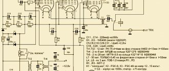
Parametric stabilizer VD1, R12 serves to increase the stability of the converter. If the converter is powered with a voltage of 9 V (from a battery), the zener diode VD1 should be excluded from the circuit, and the resistor resistance should be reduced to 30 - 50 Ohms. All converter inductors are wound on standardized frames with a diameter of 7.5 mm from IF filters of old TVs. Screens and cores of these filters are also used. The location of the coils on the frames is shown in Fig. 3 . The coils are wound turn to turn. Coils L1, L2, L3, L4 are wound with PELSHO 0.25 wire. L1 contains 2 + 5 turns; L2 – 2 + 4 turns; L3 – 5 turns; L4 – 2 turns. Coils L5 and L6 each contain 34 turns of PELSHO 0.15 wire.
The installation of the converter begins with checking the absence of installation errors, as well as measuring the operating modes of the transistors. They should be close to those indicated in the diagram Fig. 2 . If necessary, you need to select resistors R1 and R5. Then the output of the converter is connected to the antenna input of the receiver, previously tuned to a frequency of 3.6 MHz. Next, C6 is disconnected from the communication coil L4 and, through C6, a signal with a frequency of 3.6 MHz is supplied to the base of VT3 to the base of transistor VT3. By adjusting the cores of coils L5 and L6, the bandpass filter is adjusted. By restoring the L4 coil circuit, they check the performance of the local oscillator at different positions of the resistor R9 slider. The local oscillator and UHF converter are tuned by applying a signal with a frequency of 28.8 MHz to the converter input from the generator. The resistor R9 slider is set to the middle position and by adjusting the core of the inductor L3, a signal appears at the receiver output: this means that the local oscillator operates at a frequency of 32.4 MHz. The L1C2C3 and L2C5 circuits are adjusted by adjusting the cores of the L1 and L2 coils to the maximum volume at the receiver output. In the case of UHF self-excitation, it is eliminated by decreasing the resistance of resistor R4 or increasing the resistance of resistor R2. The width of the range overlap is adjusted by changing the value of resistor R10. If the receiver has a stretched tuning, then for a smoother tuning to the correspondent’s frequency you can use the receiver. The 20 meter converter is designed for receiving amateur radio stations in the range 14 – 14.350 MHz. It can work with a broadcast receiver having a range of 49 m. The average value of the intermediate frequency is 6.175 MHz. The high intermediate frequency makes it possible to almost completely suppress interference in the mirror channel. The schematic diagram of the converter is shown in Fig. 4 . The converter contains a UHF, local oscillator and balanced mixer.
The signal from the antenna An1 is supplied to the input Gn1 of the converter and then through C1 and the coupling coil L1 into the broadband input circuit. This circuit is formed by inductor L2, capacitors C2 and C3 and the capacitance of the p-n junction of the zener diode VD1. The spectrum of signals isolated by the circuit is supplied to the input of the UHF, collected on the field-effect transistor VT1. The high input impedance of the field-effect transistor cascade made it possible to completely connect the input circuit to the UHF input - to the gate of transistor VT1. The UHF load is a broadband circuit L3C5C7VD2, inductively coupled to coil L4, which is connected to the drain circuit of transistor VT1. Zener diodes VD1 and VD2, acting as varicaps, allow you to tune the input circuit of the converter and the UHF circuit to the frequency of the received radio station. The control voltage to the zener diodes is supplied from the variable resistor R1 through the decoupling resistors R2 and R3. The local oscillator is made on transistor VT2 according to a quartz-stabilized circuit. The operating mode of the transistor is determined by resistors R8, R10 and R11. From the UHF output, the received signal spectrum is fed to a balanced mixer using diodes VD3 and VD4. On the L5C12C13 circuit, a spectrum of signals with intermediate frequencies of 6 - 6.175 MHz is allocated. Coil L6 is inductively coupled to circuit coil L5, with the help of which the output signals are supplied to the antenna input of the receiver. Inductors L1 - L7 are made on frames with a diameter of 6.8 mm and a height of approximately 20 mm. Ferrite coil cores of grade 600NN (M600-3-SS2.8X14) or 100NN (100NN-2-SS2.8X14) are smooth rods with a diameter of 2.8 and a length of 14 mm, pressed at one end into threaded polystyrene plugs. All coils are wound with PEV-2 0.35 wire. L1 has 4 turns (on top of L2); L2 and L3 15 turns each (winding turn to turn); L4 – 5 turns (on top of L3); L5 – 23 turns, L6 – 10 turns (L5 and L6 piled on one frame close to each other); L7 – 30 turns (in bulk).
Installation begins with checking the installation. Turn on the supply voltage, measure and, if necessary, adjust the operating mode of the transistors according to the data on the diagram. The receiver is then tuned using a generator to a frequency of 6.175 MHz. To check the operation of the local oscillator, the output of the converter is connected to the antenna input of the receiver. Then the quartz resonator is inserted into the socket several times: this should cause an increase in the noise level at the receiver input. By adjusting the L7C16 circuit, stable local oscillator generation is achieved. The L5C12C13 balanced mixer circuit is set to a frequency of 6.175 MHz. To do this, a signal with a frequency of 14.175 MHz is supplied to the converter input from the generator. Smoothly rebuilding the converter by adjusting resistor R1 achieves the highest volume at the receiver output. Then, by adjusting the core of the coil L5, the mixer circuit L5C12C13 is adjusted to resonance at the maximum volume at the receiver output. To configure the input circuit and the UHF circuit, the receiver is tuned to a frequency of 6 MHz, and a signal with a frequency of 14 MHz is supplied to the converter input from the generator. The motor of the variable resistor R1 is set to the lowest position according to the diagram, and the rotors of the tuning capacitors C3 and C7 are set to a position corresponding to approximately 75% of the maximum capacity. Having specified the generator settings for the appearance of sound at the receiver output, by adjusting the cores of the inductors L2 and L3, the maximum volume is set at the receiver output. Then the same operation is carried out with an intermediate frequency of 6.35 MHz and an input signal frequency of 14.350 MHz. Having received the signal, adjusting the tuning capacitors C3 and C7 achieves maximum volume at the receiver output. The described actions are carried out several times - alternately at the lower and upper limits of the converter range.
source: “RADIO”, No. 4 1983, pp. 52-54; I. I. Andrianov “Attacks for radio receiving devices”, Moscow publishing house DOSAAF USSR, 1985, pp. 81-91.
Similar
Shortwave converter
A converter for the shortwave range, it just so happens that most often novice radio amateurs make CW-SSB receivers for the popular amateur radio band 80 m. Perhaps amateurs have other receivers that are not capable of receiving this or that range. In this case, you can use a simple converter to monitor amateur stations, allowing you to receive other bands (40, 30, 20, 17, 15, 12, 10m).
The short-wave converter circuit described below was used to receive the 20-meter range on the 80-meter range receiver, but nothing prevents you from supplementing the converter with additional quartz resonators and obtaining other ranges, especially since their placement is already provided on the printed circuit board. The proposed scheme is simple and quite universal. The converter described below for the short-wave range - depending on the resonators used, can be configured for 7 selected ranges. The figure shows a schematic diagram of the proposed converter.
The converter contains an input filter, a high-frequency mixer on a BF 966 (T1) MOS transistor with an LC output filter tuned to the 80 meter frequency range, and a crystal oscillator on a T2 -BF199 bipolar transistor. The mixer works in such a way that a filtered RF signal from the antenna is supplied to the first gate of transistor T1, and a signal from a generator of such a frequency is supplied to the second gate that the output signal is in the range from 3.5 ... 3.8 MHz.
To simplify the design of the input circuit, only the capacitance interacting with a constant 1 µH inductance is switched to obtain resonance at the center of a given band. Simultaneously with the change in the capacitance of the LC circuit, another resonator is connected in the generator circuit. The positive feedback required for generation is provided by the capacitive divider C1 C2.
You will immediately notice that the crystal oscillator can operate at a frequency higher or lower than the received frequency, but the choice is not so clear unless the receiver is equipped with a sideband switch. A slide switch was used to switch ranges. Popular 7×7 filters (F1−204, F2-127) can be used as filters. Of course, you can use other coils with similar inductances after changing the PCB. The table lists the frequency ranges of the converter along with the necessary elements: the values of capacitors C and resonators X.
The circuit tuning in each case is limited by the tuning of the filter core F2 and the value of the capacitors C at the highest level of the received signal. The output circuit must be tuned to the center of a given frequency or its interesting region. It may not be a big problem to purchase the necessary quartz resonators, but if the receiver's tuning range is wide enough, you can select the necessary resonators.
The presented shortwave converter can be used with CB radio stations. To do this, you need to select the value of the quartz resonators relative to the received frequency, and replace the filter with a transmission frequency of, say, 27 MHz. At one time I carried out experiments, which showed that the converter worked quite effectively with the Alan 78+ radio station. Another quite important warning is that the converter must, of course, be shielded after configuration. And the cable connecting the converter output to the receiver input must be shielded and as short as possible. I also wanted to add to any radio receiving device you need an antenna, only in this case you can get a normal result.
Circuits of simple HF direct conversion receivers using transistors
We master amateur radio broadcasting without effort and large material costsDirect conversion receivers are designed primarily for receiving radio stations with single-sideband CW and SSB modulation and are fairly simple devices in which the radio signal entering the antenna is directly converted into an audio frequency signal. Due to its simplicity and high sensitivity, as well as the absence of an HF mirror channel and combinational interference, this type of device is very attractive for a novice radio amateur who has decided to join the amateur radio broadcast through handicrafts. One of the main disadvantages of simple direct conversion receivers is the presence of a low-frequency mirror channel, which leads to doubling the reception bandwidth and, as a consequence, deterioration of the signal-to-noise parameter and selectivity in the adjacent channel.
Well, okay, enough about the sad, let's talk about the subject of discussion! And we will start, naturally, with the direct conversion receiver circuit, published in the book “The ABC of Short Waves” by the father-progenitor of the domestic SPP structure, Vladimir Timofeevich, our Polyakov. We will study this circuit in some detail, because it is the cornerstone of all receiving devices of this type and clearly demonstrates the principle of their operation.
Direct conversion receiver circuit for 80 and 40 m bands
Fig. 1 Schematic diagram of a direct conversion receiver
The signal from the antenna through coupling capacitor C1 enters the input circuit of the receiver. On the 80 m band, coil L1 is disabled, and the input circuit is formed by coil L2 and capacitor C2. The circuit is tuned to the midrange frequency of 3.6 MHz. On the 40 m range, switch B1 connects coil L1 in parallel to the input circuit. As a result, the overall inductance is reduced, and it is tuned to the average frequency of the 40 m range - 7.05 MHz. From tap L2, the signal is fed to a mixer made using diodes D1 and D2 connected back-to-back. At the same time, the local oscillator signal is supplied to the mixer through the coupling coil L4 and capacitor C9. The local oscillator operating with this mixer is tuned to a frequency half the frequency of the received signal. The receiver local oscillator is assembled on transistor T1 according to a capacitive three-point circuit. In the 80 m range, the left terminal of the local oscillator coil L3 according to the diagram is shorted to ground, and only capacitors C5-C8 are included in the circuit. Variable capacitor C5 is used to tune the receiver. With the capacitance values indicated in the diagram, the local oscillator covers the range from 1.7 to 2.0 MHz, which corresponds to the received range of 3.4-4.0 MHz. The capacitance of capacitors C7 and C8 connected to the junctions of the transistor is chosen to be large enough in order to increase the stability of the generated frequency. When switching to the 40 m range, C3 and C4 are switched on in series with coil L3. This reduces the total capacitance of the local oscillator circuit, which leads to an increase in the generated frequency. In the 40 m range, the local oscillator is tuned from 3.45 to 3.6 MHz, which corresponds to received frequencies of 6.9-7.2 MHz. For silicon diodes used in the local oscillator, the threshold unlocking voltage is approximately 0.5 V. The amplitude of the heterodyne voltage applied to the diodes is selected equal to 0.75-1 V. Thus, the diodes are unlocked only at the peaks of the heterodyne voltage, and the positive wave unlocks the lower voltage diode in the circuit, and the negative one is the upper one. That is, a mixer made on these diodes acts like a switch that closes twice during the period of the heterodyne voltage, and at its output a beat voltage is formed with a frequency fsign – 2fhet or 2fhet – fsign. The beat signal passes through a low-pass filter formed by coil L5 and capacitors C9 and C10. This filter, which has a cutoff frequency of 3 kHz, attenuates signals from neighboring stations. The filtered audio signal is amplified by a two-stage low-frequency amplifier using transistors T2 and T3 and is sent to high-impedance telephones with a resistance of at least 3.2 kOhm (for example, TA-4). With such phones, the total ULF gain is 5000-15000, depending on the current transfer coefficient of the transistors used. The receiver can be powered from a 9-12 V battery or from a low-power stabilized rectifier. The current consumed by the receiver is small - about 5 mA, so a simple stabilizer with a ballast resistor and a D813 reference diode is quite suitable. Details. In principle, any low-frequency pnp transistors are suitable for ULF, but it is desirable that T2 be low-noise, such as P27A, P28, P13B or MP39B. It is also desirable that the current transfer coefficient of the transistors used is not lower than 50-60. This will increase the ULF gain. In the local oscillator you can install KT312 or KT315 with any letter index.
The coils are wound on standardized frames from the inverter circuits and are adjusted with ferrite cores with a diameter of 2.7 and a length of 8-12 mm. The local oscillator coil L3 contains 20 turns of PELSHO 0.15 wire and is wound in the middle section of the frame (Fig. a). The L4 communication coil contains 6 turns of the same wire and is wound in the upper section. The lower section of the frame is not used. The input circuit coils are wound with PELSHO wire 0.15 turn to turn on the frames (Fig. b). L1 contains 14 turns, and L2 - 24 turns with tapping from the 5th turn, counting from the grounded terminal of the coil. Filter coil L5 is wound on a ferrite ring with a diameter of 18 and a height of 5 mm, with a relative magnetic permeability of μ = 2000 and contains 250 turns of PELSHO wire 0.1-0.15. Other rings with μ from 1000 to 3000 and diameters from 10 to 25 mm can be used. In any case, reducing the size and magnetic permeability requires increasing the number of turns.
It is advisable to equip the tuning capacitor C5 with at least the simplest vernier - this will greatly simplify tuning at the SSB station.
Fig.2 Sketch of the direct conversion receiver printed circuit board
The mounting plate (Fig. 2) measuring 200 x 55 mm is made of foil fiberglass. However, printed wiring is not at all necessary. You just need to pay special attention to the quality of grounding - common wires must be laid in several places, interconnected and connected to the receiver chassis in several places. Setting up. A correctly mounted receiver with serviceable parts begins to work, as a rule, the first time it is turned on. However, it is useful to carry out some operations in the sequence outlined below. First, the transistor modes are measured using a tester. The voltage on the T3 collector relative to ground when the phones are connected should be 6-8 V. If this voltage is less, then the resistance value of resistor R3 should be reduced, and if it is more, then increased. The voltage at the emitter of local oscillator transistor T1 should be 7-8 V. If it is less, then the rating of R1 should be increased. After setting the modes, the noise of the ULF and mixer should be faintly audible in the phones, and touching pin C11 should cause a loud low tone to appear in the phones. The receiver setup begins by setting switch B1 to the “80 m” position. The range of received frequencies is set by rotating the core of coil L3. After setting the range, adjust the input circuit by rotating the core of the L2 coil according to the maximum volume of the received signals. Then they move on to setting up the receiver in the 40 m range. In this case, the coils L2 and L3 should no longer be touched. The range of received frequencies is set by tuning capacitor C3. The input circuit is adjusted to maximum volume by core L1. For those who want to squeeze everything possible out of the receiver, you should also select the connection between the local oscillator and the mixer, changing the number of turns of the L4 coupling coil. With an insufficient number of turns, the sensitivity drops sharply, and with an excess number, along with a drop in sensitivity, the noise immunity to powerful signals also deteriorates. The receiver works well even with an indoor antenna, but it is better to use an outdoor antenna in the form of a 15-20 m beam. In this case, it is better to install a variable capacitor C1 with a maximum capacity of 25-40 pF. This capacitor will serve as an excellent volume control, and will also eliminate crosstalk from powerful stations by reducing coupling to the antenna. If power is supplied from built-in batteries, then grounding significantly increases the reception volume.
I foresee typical questions: 1. How to connect an additional ULF to the receiver for loud-speaking reception? Everything is simple here - instead of headphones, install a resistor with a nominal value of 3.3...3.9 kOhm and through a separating capacitor (1...10 μF, depending on Rin ULF) send a signal from the T3 collector to the input of an additional amplifier. 2. How to measure the signal amplitude on the mixer diodes without an oscilloscope and an RF voltmeter? Make an HF voltmeter from D1 and D2! To do this, disconnect the left terminal of any of the mixer diodes, solder a capacitor with a capacity of 0.1 μF to it with one terminal, and the second terminal of the capacitor to ground. Now you can measure the DC voltage between the terminals of the capacitor, and keeping in mind that such a simple device on silicon diodes will give a significant measurement error - the final adjustment must still be made based on the maximum level of received signals. 3. How can you regulate the amplitude of the voltage applied to the diodes without changing the number of turns of L4? Install a 3.3 kOhm tuning resistor instead of R2 and use it to set the required amplitude. 4. Which of the common transistors can be used in ULF instead of germanium ones? You can use KT3107, or any other low-power transistors with normalized (at audio frequencies) noise characteristics.
The next stop on our journey is a tri-band direct conversion receiver with a field-effect transistor switch mixer. This diagram was published in the journal Radioconstructor 2016-05 under the authorship of I. Snegerev.
Tri-band direct conversion shortwave receiver
This simple receiver receives amateur radio signals in the 7, 14 and 21 MHz bands. Among the features of the circuit design is the absence of a range switch. To understand the “zest” you need to remember that the frequencies of the amateur KB bands are located in the correct geometric progression. That is, the harmonics of the low frequency ranges end up in the high frequency ranges. Therefore, the local oscillator operates at frequencies in the 7 MHz range, and when receiving on the 14 MHz and 21 MHz ranges, the mixer operates at the second and third harmonics of the local oscillator, respectively.
Fig.3 Tri-band shortwave direct conversion receiver
The ranges in the receiver are changed by adjusting the input bandpass filter. The frequency is adjusted smoothly using a two-section variable capacitor. On the pointer handle attached to the axis of this capacitor, you need to make three marks corresponding to setting the input circuit to the ranges: 7 MHz, 14 MHz and 21 MHz. In addition to simplifying the mechanical design of the range selection circuit compared to switchable bandpass filters, this method allows, if necessary, to slightly adjust the input filter so that, for example, it tunes out interference or obtains maximum sensitivity and selectivity in the desired portion of the selected range. The signal from the antenna is fed to a dual variable resistor R1, which acts as an input attenuator. Next is a two-stage bandpass filter on circuits L2–C4.1–C1–C3–C2–C4.2–L3, tunable using a dual variable capacitor C4. Coil L1 is used to match the input attenuator with the filter. At the output of the bandpass filter, a single-ended key mixer is switched on field-effect transistor VT1, which operates as a resistance controlled by the signal supplied to the gate from the local oscillator. VT1 opens at a certain voltage level at its gate. At the same time, by changing the amplitude of the sinusoidal voltage of the local oscillator, we change the duty cycle of the opening pulses VT1. In this case (when working on harmonics), to obtain uniform sensitivity in all ranges, it is necessary that the duty cycle of the opening pulses be about four. And to do this, you need to choose VT1 with a cutoff voltage at least two times less than that of VT2. The U-shaped low-pass filter C10-L5-C11 highlights the low frequency with a bandwidth of 3 kHz. The low-frequency signal is amplified using a ULF, consisting of a pre-amplifier on transistor VT3 and a power amplifier on microcircuit A1. The local oscillator is made on transistor VT2 according to an inductive three-point circuit. The local oscillator circuit L4–C7–C6–C5 is tuned by a variable capacitor C5 with an air dielectric in the range of 6.9–7.2 MHz. The local oscillator supply voltage is stabilized by a zener diode VD1. All high-frequency coils are wound on frames from old black-and-white tube TVs with carbonyl iron cores. Both contour coils contain 12 turns of PEV 0.43 wire. Coil L1 is wound on top of L2 and contains 4 turns. Coil L4 has a tap from the 4th turn, counting from the bottom according to the diagram. A universal magnetic head from an old cassette recorder was used as the L5 coil. The head body is used as a coil screen (it is connected to the common negative of the power supply). In the mixer you can use transistors KP307A, KP307B, KP303A, KP303B, KP303I, BF245A. In the local oscillator you need to use transistors with a cut-off voltage of at least 3.5V: KP307G, KP303G, KP303D, KP303E, KP302B, KP302V, BF245C. The receiver must be powered from a stabilized source with a minimum level of ripple. The design of the receiver is shown schematically in Figure 4.
Fig.4 Design of a tri-band short-wave PPP
The body is made of foil fiberglass. All panels are soldered to each other and form a common surface connected to a common power supply negative. The installation was carried out using a three-dimensional layout method. All leads of the parts, connected to a common negative, are soldered onto the PCB foil from which the case is made. The remaining mounting points are made to hang in the air. Holes are drilled in several places on the case and mounting tabs are installed to serve as support for the positive power bus. The installation is actually made between this power bus and the foil of the housing, which is a common disadvantage. Variable capacitors are rigidly screwed to the receiver body and have reliable electrical contact with it. The metal body of C5, connected to the common negative, is also a screen covering the local oscillator circuit. Case C2 serves as a screen between the input bandpass filter coils. An additionally installed screen (dashed line) separates the low-frequency and high-frequency parts of the receiver circuit. The setup comes down to checking the functionality of the ULF. Next, using a frequency meter, you need to determine the tuning range of the local oscillator and adjust L4, and also, by selecting capacitance C7, enter it into the range of 6.9–7.2 MHz. Connect the frequency meter through a capacitor with a capacity of no more than 2 pF. The next step is to set the limits and pair the settings of the input filter circuits. Next is graduation.
Another work of comrade I. Snegerev, published in the journal Radioconstructor 2017-01 -
direct conversion HF receiver with a mixer based on a two-gate field-effect transistor .
Here's what the author writes this time: The main feature of the circuit of this receiver is that its frequency converter - demodulator, together with a smooth range generator, is made on one double-gate field-effect transistor. The receiver can be used to receive amateur radio stations with SSB or CW modulation, operating in any of five bands - 80M, 40M, 30M, 20M or 15M, it all depends on the parameters of the input and heterodyne circuits.
Fig.5 Direct conversion receiver based on a two-gate field-effect transistor
The signal from the antenna system is fed to the input circuit L1–C2–C3, tuned to the middle of the received frequency range. The frequency converter - demodulator is made on a double-gate field-effect transistor VT1 according to a circuit with a combined local oscillator, that is, both the mixer and the local oscillator are made on this same transistor. Its second gate receives a signal from the input circuit, and the first gate and source circuit form a local oscillator. Its frequency is determined by the tuning frequency of the circuit L3–C15–C10–C14–C9. The local oscillator operates at the same frequency as the input signal. The demodulated low-frequency signal is isolated at the drain of transistor VT1 and, after a simple low-pass filter on elements C6–R7–C7, is supplied through capacitor C8 to the low-frequency filter on transistors VT2 and VT3. The coils are wound on frames from the circuit of the UPCH block of an old tube TV. Such frames are plastic tubes with threaded carbonyl iron cores. Each frame has two cores. You need to remove the cores and cut the frame into two parts, then screw one core into each part. Thus, from one frame you get two. This receiver can be configured to operate in any of the amateur bands. The winding data of the coils and the capacitance of the capacitors of the input and heterodyne circuits are given in the table:
| C11 pf. | C2 pf. | C10 pf. | C14 pf. | L1, L3 vit. | L2 vit. | ||
| 80M | 1000 | 100 | 120 | 80 | 100 | 42 | 4 |
| 40M | 560 | 56 | 68 | 30 | 56 | 32 | 3 |
| 30M | 560 | 56 | 68 | 30 | 56 | 22 | 3 |
| 20M | 220 | 27 | 62 | 15 | 56 | 18 | 3 |
| 15M | 150 | 18 | 56 | 10 | 36 | 12 | 2 |
Coils with a number of turns up to 22 inclusive are wound with PEV 0.43 wire.
For coils with a large number of turns, thinner wire is used - PEV 0.23. All coils must be wound turn to turn and in one row. Coil L2 is wound on top of the already wound coil L1, after which the turns of the coils can be strengthened with paraffin or glue. Just as in the description of the previous PPP, the input and heterodyne coils must be spaced on opposite sides of the grounded control unit. This will eliminate interference from the local oscillator signal to the input circuit and increase the stability of the receiver. If the device is made in a multi-band design, the variable resistor R2 must be brought to the front panel, and on each range the amplitude of the local oscillator signal must be finely adjusted to achieve maximum sensitivity of the receiver. And on the next page we will look at several circuits of no less simple HF direct conversion receivers built using integrated circuits.
DOMOSTROYPlumbing and construction
The romance of long-distance radio travel attracts many of our readers. In the letters sent to the “Correspondence School of Radio Electronics”, you ask to tell us about the “weapons” of the shortwave radio, to provide a diagram of the KB receiver or set-top box-converter.
FIRST STEPS ON AIR
Receiving amateur radio signals is the first step for beginner shortwave radio operators. It is convenient to monitor the airwaves using a simple set-top box that connects to any tube radio with a medium wave range. This range is converted by the converter box into one of the stretched amateur HF bands.
Anyone who has experience in assembling lamp equipment can make and configure a converter.
The short-wave converter is made using one lamp and is powered by the radio rectifier. Despite its comparative simplicity, the converter has high selectivity and a fairly large gain.
As can be seen from the diagram, the signal received by the antenna An1 is fed through the capacitor C1 to the coupling coil L1 and through the inductor L2 is supplied to the grid of the lamp L1. The left triode of this lamp performs the functions of a frequency converter, and the right one acts as a local oscillator.
Switch B1a connects coil L2 with capacitors SZ-C9, which allow you to tune the oscillating circuit to the middle frequency of the corresponding range.
The local oscillator circuit consists of coil L3 and capacitors
C14-C20. The required operating mode of the right triode L1 is set by resistor R4 and capacitor C12.
The grid on the left side of the lamp receives signals from several radio stations operating in the selected range. In the anode circuit of the triode at the load, consisting of inductor Dr1 and resistor R2, a signal is released, the frequency of which is equal to the difference between the frequency of the input signal and the frequency of the local oscillator, and is fed through capacitor C11 to the input of the receiver.
The average intermediate frequency of the converter is 1.2 MHz, which corresponds to the receiver being tuned to a frequency of 1200 kHz (wavelength 250 m).
The converter parts are mounted on a small metal chassis, which, after installation, is mounted on the wall of the receiver or placed in a separate box. When placing parts, try to minimize the length of the connecting wires and place the parts near the lamp socket. Place the coils of the input circuit and local oscillator farther from one another. For example, they can be installed on opposite sides of the switch board B1.
Make coil frames with a diameter of 20 and a length of 25 mm from thick paper or cardboard. Place coils L1 and L2 on one frame. Communication coil
Converter for amateur bands
Using this simple amateur band converter, any receiver with a mid-wave range can receive signals from amateur radio stations in the ranges 28.07 - 29, 21 - 21.45, 14 - 14.35 and 7 - 7.1 MHz. Even a novice radio amateur can carry out the design. Very few parts are required to make it. Despite its simplicity, the converter provides good selectivity and sensitivity.
Shortwave converter to medium wave radio
Radio broadcasting on the medium wave range (MW, MW) has now almost completely ceased in many regions. You can only “catch” some distant foreign stations at night, but very few and with very mediocre quality. You can not only “revive” an old AM radio, but also make the reception very interesting by switching it to short waves.
The shortwave range is different. that, thanks to multiple tropospheric reflection, the signal travels very far, and even a very simple receiver can receive very distant radio stations, so to speak, “from the other side of the world.”
This can be very useful for a language learner because you can listen to radio broadcasts from the country whose language you are learning. Here is a description of the circuit of a simple short-wave converter that allows a CB (MW) radio receiver to receive signals in the short-wave range “31 meters”. Currently, this is the most “densely populated” HF band.
The important difference between this converter is that... that it does not need to be connected to the radio, but only placed next to its magnetic antenna. The fact is that most CB (MW) radio receivers do not have an antenna socket, and reception is carried out only through an internal magnetic antenna, which is a volumetric coil with a ferrite core. This converter has the same output coil. If they are placed next to each other, a connection will arise between them and the signals from the converter will be received by the CB (MW) radio receiver.
The circuit is shown on the radiochip website. Made on two field-effect transistors. Transistor VT1 is a frequency converter, and transistor VT2 is a heterodyne. The signal is received by external antenna W1. This can be either a whip antenna or a piece of mounting wire. The longer, the better the reception. The input circuit L1-C2 is set to the middle of the 31 meter range, that is, at 9.65 MHz. It is best to pre-set it using a generator, but you can also “by eye”, receiving radio stations and achieving greater sensitivity. However, this is a painstaking process.
Quartz resonator Q1 with a frequency of 8863kHz; such resonators are used in various video equipment. Coil L1 is frameless, its internal diameter is 18 mm, it contains 14 turns of PEV 0.64 wire (or another diameter from 0.5 to 1 mm). Adjustment - by compressing/stretching its turns. Coil L2 is wound with the same wire on a ferrite rod with a diameter of 8 mm and a length of at least 100 mm. Contains 100 turns. Power source – 6F22 battery (analogous to Krona).
