This term has other meanings, see Victoria.
Victoria-001-Stereo
- a top-class radio produced by the Riga Radio Plant.
In 1973, the radio industry of the USSR began producing the country's first top-class stereo radio, made entirely on semiconductor devices (abbreviated SRP-V - top-class stereo semiconductor radio) - Victoria-001-stereo radios (previous top-class models, such as "Estonia-006-stereo", despite the use of only transistors in the UMZCH, contains tubes in the tuner). This radiogram is the base model for the development and release of subsequent high-end radiograms entirely on transistors.
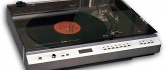
The numbers in the name of the radio mean the following: the first one is “0” - the highest class of the model, the subsequent ones are “01” - the modification number. The Victoria-001-stereo radio is equipped with an I-EPU-73S electric player, which is also the first high-quality electric player in the USSR.
Layout
The radio is made in the form of three separate devices (not counting speaker systems): a tuner, an electric player (EPD), and an amplifier-switching device (ACU). It was produced in two versions: floor-mounted and shelf-mounted. In the first case, these three nodes are placed in a common box, but in different compartments. In the lower left corner there is a UCU, in the upper left there is an EPU, in the upper right there is a tuner, and in the lower right, not occupied by electronic components, for symmetry there is a drawer for storing something. In the second case, these devices are made in separate housings. They are connected by cables (in the documentation designated as “hoses”, according to the tradition adopted by the developers of sound film equipment) with connectors.
Transistor radio "Victoria-001-stereo"
V. I. Deryabin, V. G. Ponimansky
TRANSISTOR RADIO
“VICTORIA-001-STEREO”
© Svyaz Publishing House, 1976,
PREFACE
In 1973, the domestic radio industry began producing the first high-class stereo radio in our country, made entirely on semiconductor devices (abbreviated as SRP-V - high-class stereo semiconductor radio) - the Victoria-001-stereo radio. This radiogram is the base model for the development and release of subsequent high-class transistor radiograms.
The numbers in the name of the radio mean the following: the first one is “0” - the highest class of the model, the subsequent ones are “01” - the modification number. The Victoria-001-stereo radio is equipped with a 1-EPU-73S electric turntable, which is also the first high-quality electric turntable in our country.
The possibility of producing a top-class radio, made entirely on semiconductor devices, is due to the development by the domestic industry of the production of high-quality semiconductor devices, &
namely field-effect transistors, transistors with low noise figure, powerful output transistors and varicaps.
This book is a continuation of the material on high-end radios. Tube radios of the highest class are discussed in the book by V.I. Deryabin and V.G. Ponimansky “Stereophonic tube radios of the highest class.” This book contains the requirements for stereophonic radios of the highest class and the basic principles of constructing these radios. This book also discusses the basic principles of domestic stereophonic radio broadcasting and the peculiarities of the operation of stereo radios in the mode of receiving stereo broadcasts, familiarization with which is recommended for a better understanding of the operation of the Victoria-001-stereo radio. The issues of domestic stereophonic radio broadcasting are covered much more widely in the literature [2] and [3].
Top-class stereo radios are the most complex models of broadcasting equipment, the complexity of their circuits and designs is steadily increasing. Therefore, to carry out repairs and professional installation of the Victoria-001-stereo radio, you need knowledge of its electrical circuit, the principles of operation of its components, blocks and devices, as well as knowledge of the design and installation of the entire radio. These issues are covered in detail in the first sections of the book.
The book will help you appreciate the high qualities of our country's first top-class transistor radio. The authors thank the reviewer A. M. Pil-takyan for valuable comments that were taken into account when working on the book manuscript.
Reviews and suggestions should be sent to the publishing house "Svyaz" (101000, Moscow Center, Chistoprudny Boulevard, 2),
I. _ GENERAL CHARACTERISTICS OF THE RADIO
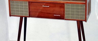
Radiola "Victoria-001-stereo" is a transistor superheterodyne stereo broadcast receiver of the highest class, made together with a stereophonic electric player of the first class in one floor-mounted box (Fig. 1.1). The radio's acoustic system is remote and consists of two sound speakers with connecting cords 4.5 m long.
Rice. 1.1. Appearance of the Victoria-001-stereo radio
Radiola provides reception of radio broadcasting stations operating with AM in the DV, SV, five extended KB bands, with FM in the VHF band, reception of stereo programs in the VHF band and playback of stereo and monophonic records. Radiola also provides recording and playback of programs using a plug-in monophonic or stereophonic tape recorder of any type.
The radiola has the following devices that create convenience during its operation: a rotating magnetic antenna (for operation in the LW and MW bands); built-in dipole (for operation in the VHF range); stepwise adjustment of the bandwidth in the DV, SV and KB ranges; dial indicator for precise tuning to a station in all ranges; AFC in the VHF range; automatic switching on of the stereo broadcast reception mode; step change in timbre; stereo balance adjustment; a separate button for recording onto a tape recorder. The radio also provides the ability to receive one of three fixed stations within the VHF range with pre-tuning to them. A stereophonic electric player installed in the radio recorder ensures that when the EPU is turned on, the pickup is automatically installed on the record, and when playback is complete, the EPU is automatically turned off and the pickup is returned to the stand. The electric player also has a built-in stroboscopic device for monitoring and adjusting the rotation speed of the EPU disk. The main indicators of the Victoria-001-stereo radio are given in Appendix 1.
Controlling the Victoria-001-stereo radio is relatively complex, and the controls in the radio have mostly abbreviated or symbolic symbols, so the main functions performed by the corresponding knob or button should be noted (Fig. 1.2). The radio is turned on and off using the Network button (36),
selection of the type of work - by turning on one of the buttons:
Radio (35), Sound Recorder (34)
and
Tape Recorder (33),
as well as
the Record (32)
and
Stereo (31) buttons.
The stereo balance is adjusted using the
Balance knob (29),
the volume is adjusted using the
Volume knob (26),
and the tone is adjusted using the
Low (28)
and
High (27) knobs.
Stepwise change of timbre is made by the
Speech button (30).
When buttons
30
-
36
displays 1 -
7,
which are located above the corresponding buttons, are illuminated.
The magnetic antenna is rotated using the MA handle (25). Changing the bandwidth in the DV, SV and KB ranges is carried out using the UP (narrow band) (24), SP
(middle band)
(23)
or
ShP (wide band) (22) buttons.
By pressing the
U(21)
and
U1(P)
, the VHF band is turned on, the
D button (19)
- the DV range, the C button
(17)
- the CB range, the
K button (16)
- the HF range.
Knob 14
sets the required HF range.
Turning on the AFC in the VHF band or the magnetic antenna in the DV and MF bands is done with the AFC/MA button (18),
and turning on the monophonic operating mode in the VHF band is done with the Mono
Activation of fixed settings in the VHF range is carried out using buttons
U4 (8), UZ (9)
or
U2 (10).
The fixed setting is set using the knob located on the corresponding fixed setting button.
Tuning to a station in all ranges is done Tuning knob (15),
and fine tuning is determined using indicator
12.
The reception mode of stereo broadcasts in the radio is indicated using the
Stereo indicator (13).
Rice.
1.3. Radio "Victoria-001-stereo" (rear view): 1 - socket for connecting an external antenna for the DV, SV and KB ;
2 - Antenna socket. VHF; 3 — socket for grounding connection;
4 -
socket.
Close reception;
5 — connecting cable for the built-in VHF antenna;
6 —
socket
;
7 - connecting cable for supplying a signal from the tuning unit to the power amplifier unit;
8
— cable for supplying a signal from the electronic control unit to the power amplifier unit;
9 —
mains voltage switch;
10 —
network interlocking socket with fuse;
11 — fuse for the power supply circuit of the EPU engine (Pr2);
12 — socket
Player;
13 — tape
recorder socket!;
14 — socket
Tape recorder 2;
15 — socket
Setting block;
16 — socket
Left speaker system;
1 7 — socket
Right speaker system.
The location and purpose of the sockets on the rear wall of the radio are shown in Fig. 1.3. Dimensions of a box on legs with a radio and an electric player (Fig. 1.1, pos. a, b, c, d)
- 950 X 350 X 675 mm, weight - about 36 kg.
Dimensions of the sound speaker with stand (Fig. 1.1, item e)
- 360X270X675 mm, weight - about 18 kg. As can be seen from the indicated dimensions, the height of all radiol boxes is the same, which gives the radiol a more strict form and meets modern requirements for the artistic design of household radio equipment.
Rice. 1.4. Electrical connection diagram for the radio
To reduce the size of the radio, the ease of its manufacture and configuration, as well as to create a more favorable operating temperature, the Victoria-001-stereo radio receiver is made in the form of two separate functionally complete devices - a tuning unit (see Fig. 1.1, item b)
and a power amplifier block (see Fig. 1.1, item c). The tuning unit contains the entire high-frequency part of the radio receiver, and the power amplifier unit contains the low-frequency part and power supply for the radio. The electric player is also made in the form of a separate block and is located in the electronic control unit compartment (see Fig. 1.1, pos. a). The signal is supplied from the tuning unit and the electric player to the power amplifier unit through connecting cables to the corresponding sockets on the back of the radio (see Fig. 1.3). The electrical connection diagram in the Victoria-001-stereo radio is shown in Fig. 1.4. In the box of the radio receiver with the electric player, there is a compartment for storing gramophone records, located under the tuning unit (see Fig. 1.1, pos. d).
The Victoria-001-stereo radio is made of 67 transistors and 44 diodes. The operation of the electrical circuit and the design of the radio are discussed below.
2. RADIO SETTING BLOCK
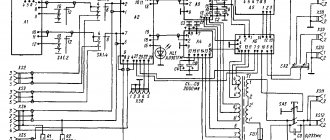
2.1. Schematic diagram of the tuning unit
General information.
The Victoria-001-stereo radio tuning unit (Fig. 2.1) consists of functional blocks: VHF, RF (radio frequencies), HF (short waves), IF, stereo decoder, FN (fixed tuning), KXIE and magnetic antenna assembly1).
In the tuning unit, a range is selected, tuning to the required station, amplification of HF signals, converting them into IF signals and detection, decoding of a complex stereo signal, as well as all switching of HF circuits in the radio. The output signals of the tuning unit (LF signals) are removed from its socket Ш4
(see Fig. 2.1) and fed to the input of the LF radio transmission path, for which the tuning unit is connected by cable to the power amplifier unit (see Fig. 1.4).
Electrical diagrams of the functional blocks shown in Fig. 2.1 conditionally (in the form of rectangles), will be given below when considering the operation of the tuning unit circuit. For a better understanding, consideration of the operation of the Victoria-001-stereo radio tuner circuit will be carried out along paths, i.e., through parts of the circuit that ensure the passage of certain signals (HF, IF, etc.).
High frequency FM signal path. Electronic tuning using varicaps. Fixed settings in the VHF range.
In the high-frequency path of FM radio signals, signals are received within the VHF range, the received signals are amplified and they are converted into IF signals.
The HF FM signal path in the radio consists of a built-in VHF antenna, an antenna transformer Tr
(see Fig. 1.4), a VHF unit, a variable electronic tuning resistor
R8
and a FN unit (see Fig. 2.1),
The built-in VHF antenna is a symmetrical loop vibrator (VHF dipole) with a characteristic impedance p equal to 300 Ohms. The vibrator is made of CATV type cable and has a total length of 1800 mm. The antenna is located inside the radio case and is connected to the input of the VHF unit through an antenna transformer.
The antenna transformer (Fig. 2.2a) matches the built-in symmetrical VHF antenna with the asymmetrical radio input, which has an input impedance of 75 Ohms. The antenna transformer is mounted on a getinax plate (Fig. 2.26), on which a ferrite core with windings and support petals is installed. The antenna transformer is connected to the tuning unit socket using a RK-75 cable with a plug (connector A
GOST 9042 - 65). The cable is attached to the plate using a bracket. The antenna transformer winding data is given in Appendix 4.
Rice.
2.1. The electrical circuit diagram of the antenna tuning unit with a characteristic impedance of p - 75 ohms creates additional convenience when operating the radio, namely, it allows the use of external antennas of various types: asymmetrical, directional multi-element (television), etc. Pages: 1
Architecture
Tuner
This device consists of five blocks: VHF, fixed VHF settings (FN), AM frequency converter, designated as a radio frequency (RF) unit, intermediate frequency amplifier (IFA), stereo decoder (SD).
The VHF unit is made on transistors: GT328A, two GT313A, one KT315B.
The FN block does not contain active elements.
The RF unit is made on four GT322A transistors.
The IF unit is made on five transistors GT322A, five KT315A, three KT315B, two MP25B.
The LED block is made on three MP41A, four MP25B, one GT308B, and one GT402B transistors.
The tuner does not have its own power supply, since it is powered by the UCU.
UCU
This device consists of a power supply, a switching unit and two identical pre-amplifier units.
The switching block does not contain active elements.
The power supply contains transistors P304, P213B, GT402B, KT315B, two KT807A.
Each of the two pre-amplifier blocks contains transistors: KP103E, three KT315A, MP26, P307A, two GT402V.
Outside the blocks there are five KT805A transistors, of which one is used in the power unit of the compensating stabilizer, and the remaining four are in the final stages of the amplifier (two per channel).
EPU
It includes the actual electric player I-EPU-73S (33⅓, 45, 78 rpm) with a strobe light on a thyratron with a cold cathode MTX-90, equipped with a magnetic pickup head GZUM-73S. as well as an amplifier-corrector unit of the UNCHZ-2 type pickup. This block consists of two identical stereo channels made on a common board, made with transistors: two P28, GT309G, GT308E, KT315B.
Excerpt characterizing Victoria-001-Stereo
- Drubetsky? - No, recently... - What do you like about him? - Yes, he is a nice young man... Why are you asking me this? - said Princess Marya, continuing to think about her morning conversation with her father. “Because I made an observation, a young man usually comes from St. Petersburg to Moscow on vacation only for the purpose of marrying a rich bride. – You made this observation! - said Princess Marya. “Yes,” Pierre continued with a smile, “and this young man now behaves in such a way that where there are rich brides, there he is.” It’s like I’m reading it from a book. He is now undecided who to attack: you or mademoiselle Julie Karagin. Il est tres assidu aupres d'elle. [He is very attentive to her.] - Does he go to see them? - Very often. And do you know a new style of grooming? - Pierre said with a cheerful smile, apparently in that cheerful spirit of good-natured ridicule, for which he so often reproached himself in his diary. “No,” said Princess Marya. - Now, in order to please Moscow girls - il faut etre melancolique. Et il est tres melancolique aupres de m lle Karagin, [one must be melancholic. And he is very melancholy with m elle Karagin,” said Pierre. - Vraiment? [Really?] - said Princess Marya, looking into Pierre’s kind face and never ceasing to think about her grief. “It would be easier for me,” she thought, if I decided to trust someone with everything I feel. And I would like to tell Pierre everything. He is so kind and noble. It would make me feel better. He would give me advice!” – Would you marry him? asked Pierre. “Oh, my God, Count, there are moments when I would marry anyone,” Princess Marya suddenly said to herself, with tears in her voice. “Oh, how hard it can be to love a loved one and feel that... nothing (she continued in a trembling voice) you can’t do for him except grief, when you know that you can’t change it.” Then one thing is to leave, but where should I go?... - What are you, what’s wrong with you, princess? But the princess, without finishing, began to cry. – I don’t know what’s wrong with me today. Don't listen to me, forget what I told you. All Pierre's gaiety disappeared. He anxiously questioned the princess, asked her to express everything, to confide in him her grief; but she only repeated that she asked him to forget what she said, that she did not remember what she said, and that she had no grief other than the one he knew - the grief that Prince Andrei’s marriage threatens to quarrel with his father son. – Have you heard about the Rostovs? – she asked to change the conversation. - I was told that they would be here soon. I also wait for Andre every day. I would like them to see each other here. – How does he look at this matter now? - Pierre asked, by which he meant the old prince. Princess Marya shook her head. - But what to do? There are only a few months left until the year ends. And this cannot be. I would only like to spare my brother the first minutes. I wish they would come sooner. I hope to get along with her. “You have known them for a long time,” said Princess Marya, “tell me, hand on heart, the whole true truth, what kind of girl is this and how do you find her?” But the whole truth; because, you understand, Andrei risks so much, doing this against the will of his father, that I would like to know... A vague instinct told Pierre that in these reservations and repeated requests to tell the whole truth, Princess Marya’s ill will towards her future daughter-in-law was expressed, that she I wanted Pierre not to approve of Prince Andrei’s choice; but Pierre said what he felt rather than thought. “I don’t know how to answer your question,” he said, blushing, without knowing why. “I absolutely don’t know what kind of girl this is; I can't analyze it at all. She's charming. Why, I don’t know: that’s all that can be said about her. “Princess Marya sighed and the expression on her face said: “Yes, I expected and was afraid of this.”
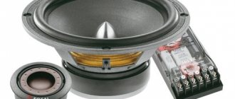
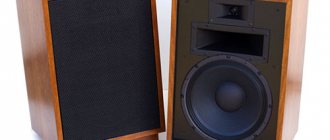
Acoustic system Victoria 001, AS-40-8 “Victoria”
4685
35
113
23.02.2021
vladbatin: photographer of new times St. Petersburg
70099
277
144
04.02.2012
RU
Video description:
Perfect technical condition, wonderful aura and amazing sound; 3-way closed-type speakers Nominal frequency range: 40 – 16000 Hz Uneven frequency response of sound pressure: 16 dB Average standard sound pressure: 0.2 Pa Nominal impedance: 8 Ohm Nominal power: 8 W Speakers used: LF: 8 GD-1 -25 MF: 4 GD-6-160 HF: 3 GD-2-4500 Filter cut-off frequency: 420 Hz and 5000 Hz Overall dimensions (HxWxD): 675x350x270 mm Weight: 18 kg The acoustic system was included in the set of the high-class transistor radio "Victoria" 001-stereo" and "Victoria 002-stereo". The body is made of birch plywood 10 mm thick. The back wall is removable, 10 mm thick, and also made of plywood. The side walls are finished with precious wood with a matte or shiny polish, and the front panels are covered with decorative radio fabric. The internal volume of the box is sealed and filled with cotton wool. The speaker housings are mounted on two wooden stands glued to the bottom. All direct radiation heads are installed on the front panel of the speaker on the same vertical axis. The internal volume of the speaker is about 50 liters. In a loudspeaker, all direct radiation heads operate in phase, which is necessary to obtain a uniform frequency response of sound pressure within its nominal frequency range. The midrange and high-frequency heads are closed from the inside with a plastic cover and filled with cotton wool to protect the low-frequency head from radiation. The separation filters are mounted on a metal base, which is attached to the bottom of the box. The filter uses MBGO capacitors and air core coils. Coils L1, L2 and L3 are wound with PEV-1 wire with a diameter of 1.12 mm on cylindrical polystyrene frames with a diameter of 40 mm. The winding height of coils L1 and L2 is 28 mm, and L3 is 14 mm. Coil L1 contains 310 turns, L2 - 235 turns, L3 - 72 turns. Source:ldsound Sincerely, BATIN PROduction +7911-11-90790 mailto:vladbatin