Having been satisfied after assembling a mono amplifier on the TDA2005, the decision came to build a stereo amplifier on the same chip.
Let’s immediately list the characteristics that the manufacturer claims:
- Supply voltage (V)……………………………………………………6-18
- Peak output current (A)……………………………3
- Quiescent current (mA)…………………………………………..75
- Reproducible frequency range (Hz)………………..40-20000
- Harmonic distortion factor (%)……………………….1
- Nominal load resistance (Ohm)…………………..3.2
- Minimum load resistance (Ohm)…………………….2
- Output power (W at 18 V supply voltage)……..22
- Input sensitivity (mV)………………………………….300
- Gain (dB)……………………………………………………….50
TDA 2005 amplifier with good characteristics.
In addition, you need to take into account its useful qualities:
- load short circuit protection;
- overheat protection;
- protection against power surges in the range up to 40 V;
- the amplifier has a wide range of supply voltages from 6 to 18 V.
The printed circuit board from 2005 was made in lay. Built taking into account the use of convenient terminal blocks.
Download the board
One of the methods to reduce interference would be to connect the microcircuit housing to the minus of the general power supply.
Recommendations for elements:
- It is advisable to purchase capacitors for 25 Volts;
- resistors, the best option is 0.25 watts;
- Be sure to purchase input wires with shielding, this will protect you from additional interference and extraneous sounds
This car amplifier circuit based on TDA2005 has a number of advantages:
- speed of production;
- obtaining quite decent equipment;
- low cost of production.
At the output we get an amplifier measuring 70mm x 41mm:
Sound quality is acceptable. Pop and metal are played well. The bass doesn't mix into mush.
Bridged amplifier 20 W on TDA2005
Comments (31): #1 Slipknoter48 March 25 2011 +14
Thank you very much, but I would suffer again for a long time) very good site! +5
#2 Slipknoter48 March 31 2011 +8
Why might there be a strong background?
#3 root April 01 2011 +9
Maybe due to a bad power filter, try replacing and increasing the capacity of the electrolytic capacitor, which is located after the diode bridge in the rectifier. C5 is used as a power supply filter in the above circuit, try changing it. Also, the background may be due to interference in the input circuits. The wires carrying the signal to the amplifier input must be shielded, and the shield must be connected to the common one (minus).
#4 Slipknoter48 April 02 2011 +11
with C5 everything was fine, I installed a rectifier at the output of 2 4000mk 50V condensers and shielded everything possible, the background was blown away) now another problem is the bass is wheezing, what could it be? Everything is fine with the column.
#5 root April 02 2011 +9
In this case, there are more options, I’ll give you the ones I came across:
- It is most likely that the power supply cannot withstand the load; when driving this amplifier, it consumes considerable current. Try connecting the circuit to a more powerful power supply or to a high-capacity 12V battery.
- Perhaps at high volumes the signal source itself is distorted (it is faulty or the equalizer is poorly configured), try connecting a player to an amplifier or taking a signal from a computer sound card.
- You came across a defective microcircuit, try to replace it with one purchased from another store (it often happens that you come across a batch of defective ones).
- Adjust the feedback circuit further - R1, C1, C2. Instead of R1, we turn on a variable resistor; it is advisable to check C1, C2. We supply power and signal to the amplifier, achieving normal gain without distortion or overload.
#6 Alexander December 24 2014 +7
What's the problem people? I assembled the amplifier according to the second circuit, after turning it on, after about 5 minutes the electrolyte capacitor C5 heats up, and noise and hissing begin, maybe the reason for this is in the resistors R2, R3 I set to 0.8 ohms, or in the ceramics C4, C6,..C9?
#7 root December 24 2014 +13
The publication was updated and put in order; the old information and diagram from Bashirov’s brochure were removed because the diagram and printed circuit board there did not match and there were other errors.
Alexander, it’s very strange that capacitor C5 is heating up, from what source are you powering the circuit? - you need to feed it with rectified constant voltage - a step-down transformer + diode bridge, at the output we get a constant voltage.
#8 Alexander December 24 2014 +8
In general, I found and fixed the error, it turns out I mixed up the polarity of the capacitor, I am powered by a Soviet power supply unit 6-9 volts 0.1 ampere, constant. I am very grateful to the site for the diagram and help in setting up. For updating the site 5+
#9 Nazar February 24 2015 +9
Why does the finished amplifier play quietly?
#10 root February 24 2015 +8
Nazar, here are some recommendations for troubleshooting and their possible causes:
- Check for shorts between tracks and other debris on the printed circuit board;
- The signal level at the amplifier input is low; for the experiment, apply a signal to the amplifier from another source;
- Weak power supply, there is not enough current to drive the ULF, try powering it from a battery or a powerful power supply;
- One or more electrolytic capacitors are faulty - check the charge/discharge tester and try to replace them;
- Resistor R1 is soldered to a different value;
- The microcircuit is scorched, check whether it gets too hot in idle mode, try replacing the microcircuit.
#11 Evgeniy March 16 2015 +5
A good amplifier put together such a mono. I'm pleased with the gain factor, the S90 rocks. Collected according to the production seal. Can be downloaded from lay at https://ampexpert.ru/usilitel-20-vt-na-tda2005-mono/
#12 Alexander March 27 2015 +4
good afternoon. I have such a situation, the amplifier perceives interference from the signal source, from the DVD player there is a whistle from the computer, clicks, from the phone small whistles are barely perceptible but are there. I sinned on the power supply, connected it to the computer unit and the same thing, then I wandered around various sites and found that there are circuits where a high-frequency transistor SS9014 is placed at the input of the microcircuit, I think you just need to raise the frequency at the input a little so that it does not coincide with the network, but I don’t know how much this will help, since the sound goes from 20 to 20 000 Hz, which means raising the frequency to at least 100 Hz, allowing it to be plugged in from the mains, but what about the sound if the sub is at 20-40 Hz, but in fact it can help or can you not experiment with it?
#13 root March 27 2015 +4
Here's what to try:
- connect a 47-100 kOhm variable resistor to the amplifier input to adjust the volume. The middle leg of the resistor goes to C6, one of the outer ones goes to the ground, after which we send a signal to the remaining outer leg and the ground.
- Between pin 1 of the microcircuit and ground, connect a 100 pF capacitor and a 30 kOhm resistor connected in parallel. Set capacitor C6 to 0.47 - 1 µF, not electrolytic.
- To connect the player and other signal sources to the amplifier, use a shielded cable, connect the screen itself to ground (common) in the diagram, it will also serve as a minus.
#14 Alexander March 27 2015 +8
Using this circuit, I put together a simple experiment about the speakers, but as it shows, it works normally, only the only noise is at the input, while I’m working on your advice, I’m trying to determine which capacitors are coming from which leg.
#15 root March 27 2015 +7
According to the diagram you provided, there is no point in turning on the speaker like this - the power delivered will be equal to the power of one channel, or even less. Look at the wiring diagram for the microcircuit in this article and compare it with the one you provided: legs 4, 2 (feedback) and 5, 1 (inputs). Bridged ULF is not just about connecting a speaker to the output of each channel.
#16 Alexander March 27 2015 +4
eureka no noise, something was wrong with the power supply from the computer for some reason it was noisy, then I connected it to a trance with a block of capacitors and a diode bridge, it was the same thing, then I connected 2 small 10 uF capacitors from the ground to the radiators, then I connected the volume control 1 to 33 com 0.25 watt and the other in series at 100 kom 0.25 watt and surprisingly, the noise disappeared, the background remained in the case from the power supply, you will probably need to go through all the capacitors in the power supply, maybe you need to replace it, and I realized that you need to put trimmers at the input to reduce the input power at 47-100 com and variable volume at 47-100 com, and then the noise goes away.
#17 Evgeniy January 09 2022 +4
Hello, dear radio amateurs, I would like to ask you for help... This is the first time a problem has arisen with this amplifier! Before this, I assembled an amplifier exactly according to your mono circuit and everything worked perfectly without any problems, but now the problem is the following: after assembling the amplifier, two resistors, R2 and R3, get wildly hot, the output sound is dirty and with wild interference. I checked everything carefully, there is no short circuit anywhere, the amplifier is assembled according to the same circuit and works perfectly, I connect this one, and it... In general, I would really like to know, maybe the reason is that this amplifier is a TDA2005R, and the old one — just TDA2005? Please help me figure it out...(
#18 root January 10 2022 +6
Evgeniy, in your case you need to make sure that the power supply is powerful enough and the voltage drop under load is not very large. It is possible that one of the channels of the microcircuit is scorched or there is a manufacturing defect. Heating of resistors R2 and R3 may indicate that the amplifier is overexcited and operates as a generator. The reason may be a poor layout of the printed circuit board, a malfunction of one of the capacitors or one of the channels of the microcircuit. TDA2005R is a newer version of the chip, the inclusion is the same as for TDA2005. For this microcircuit, it is better to use a switching circuit with a voltage boost (boostrap), as in Figure 5, this will slightly increase the ULF output power.
#19 Alexander April 23 2022 +6
In general, it is better and more reliable to always take the diagrams from the datasheet itself. Then there will be fewer problems...
#20 Alexander December 30 2022 +2
Hello, please help me with the diagram in Fig. 5. What 2.2 µF capacitors can be installed, I can’t find them, will 4.7 µF be suitable? Thank you.W
#21 root December 30 2022 +2
Hello. You can set it to 1 µF, 3.3 µF or 4.7 µF. Capacitor C1 in Figure 5 can be installed non-polar, for example mica or film.
#22 Alexander December 30 2022 +2
Thank you for your answer, if you find it difficult, please tell me, I can’t find 12 Ohm resistors, what can I replace them with? Thank you.
#23 root December 30 2022 +2
It is advisable not to deviate too much from the denominations used in the diagram. Try setting R4 and R5 from Figure 5 to 10 Ohms or 9.1 Ohms.
You can get about 12 ohms from several individual resistors - for example, connect two 4.7 ohm resistors in series and get a total resistance of 9.4 ohms. Or connect two 24 Ohm resistors in parallel - the total resistance will be 12 Ohms.
Formula for calculating resistance for series-connected resistors:
Rsum = R1 + R2 + … Rx.
For parallel connected resistors:
1/Rsum = 1/R1 + 1/R2 + …. 1/Rx.
#24 Alexander March 20 2022 0
How is the datasheet signet itself properly wired? On some forums they wrote that it wasn’t very good...what can you say? Is it possible to poison her, such a fee?
#25 Alexander March 20 2022 0
I’ll make a reservation, the datasheet signet, (pavement), I meant about it.
#26 root March 20 2022 0
The printed circuit board for the bridge version of the TDA2005 from the datasheet is laid out well.
#27 Alexander March 21 2022 +1
Dear root, what pre-amplifier (pre-amp) would you recommend for it?
#28 root March 22 2022 0
Alexander, look in the categories:
- Preamp Circuits
- Tone controls and equalizers
Several tone block schemes:
- Low-frequency pre-amplifier circuit with tone control (LM741)
- Circuit diagram of a three-band tone block based on op-amp TL082 (power supply +-5V)
Also, preamplifiers and tone controls can be found in low-frequency power amplifier circuits on microcircuits.
#29 Kirill March 28 2022 +1
Is this circuit suitable for the tda2005Vm amplifier?
#30 Alexander March 29 2022 +1
root, thank you very much for the information... We'll choose...
#31 Alexander March 30 2022 +1
Kirill, of course it will do, just to be more sure, take the second diagram, it’s a datasheet one...
LF amplifier on TDA2005 - design description
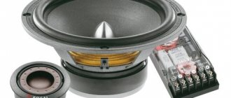
It is based on the TDA2005 integrated circuit, which has two independent outputs in its structure. The circuit is quite simple, so it won’t be too difficult to assemble it yourself.
The circuit operates in standard connection. The degree of bass amplification of each of the individual channels is determined by the resistance of resistors R3 and R5, which can be changed in the range from 10 to 47 Ohms. To remove heat, the TDA2005 integrated circuit must be installed on a radiator with an area of at least 20 square meters. see. The radiator then needs to be connected to the common wire of the circuit.
Technical characteristics of the TDA2005 amplifier
- Supply voltage: from 8V to 18V;
- Maximum current consumption: 3.5 A;
- Output power: RL=4 Ohm - 20 W;
- Bandwidth (at -3 dB level): 40…20000 Hz;
- Quiescent current - 50 mA.
Bass amplifier assembly
Assembling the low-frequency amplifier circuit is quite simple and not particularly difficult. The parts are mounted on a board made of one-sided foil fiberglass. It is written in detail how to make it with your own hands. First, resistors and capacitors are soldered, paying attention to the correct polarity and the serviceability of the capacitors, which are desirable.
The TDA2005 chip must first be attached to the heatsink and then installed on the board. After carefully checking the installation and the absence of errors, we connect the speakers to 12 V. Next, you need to measure the current consumption. At rest it should be at 60 mA. A power source with a voltage of 12 - 15V and with a load current of more than 1.5 A. The capacitor in the power supply filter must have a capacity of at least 4700 µF.
Satisfied after assembly, the decision came to build a stereo amplifier on the same chip.
Let’s immediately list the characteristics that the manufacturer claims:
- Supply voltage (V)……………………………………………………6-18
- Peak output current (A)……………………………3
- Quiescent current (mA)…………………………………………..75
- Reproducible frequency range (Hz)………………..40-20000
- Harmonic distortion factor (%)……………………….1
- Nominal load resistance (Ohm)…………………..3.2
- Minimum load resistance (Ohm)…………………….2
- Output power (W at 18 V supply voltage)……..22
- Input sensitivity (mV)………………………………….300
- Gain (dB)……………………………………………………….50
TDA 2005 amplifier with good characteristics.
In addition, you need to take into account its useful qualities:
- load short circuit protection;
- overheat protection;
- protection against power surges in the range up to 40 V;
- the amplifier has a wide range of supply voltages from 6 to 18 V.
The printed circuit board from 2005 was made in lay. Built taking into account the use of convenient terminal blocks.
One of the methods to reduce interference would be to connect the microcircuit housing to the minus of the general power supply.
- It is advisable to purchase capacitors for 25 Volts;
- resistors, the best option is 0.25 watts;
- Be sure to purchase input wires with shielding, this will protect you from additional interference and extraneous sounds
This car amplifier circuit based on TDA2005 has a number of advantages:
- speed of production;
- obtaining quite decent equipment;
- low cost of production.
At the output we get an amplifier measuring 70mm x 41mm:
Sound quality is acceptable. Pop and metal are played well. The bass doesn't mix into mush.
Now let's move on to the most interesting part, testing.
I’ll note right away that the circuit and printed circuit board on which the amplifier is assembled were taken from the Internet and are positioned as the most popular. Let's get started.
The amplifier was tested on Soviet speakers with an impedance of 4 Ohms. Transformer power supply 18 volts.
In terms of power supply: the amplifier starts working at 3 volts, although not very well, it choke at low frequencies. Already at a voltage of 19 volts the protection is triggered. Optimal power supply is 14 volts 3 amps.
The microcircuit gets very hot, so make sure you have a good heatsink, and it’s a good idea to use thermal paste.
Amplifier output impedance: oddly enough, but the readings are 0 Ohm.
The frequency response surprised me, it’s quite straightforward