VHF radio unit “Estonia-006-stereo”
The VHF radio unit “Estonia-006-stereo” is made of two lamps.
A UHF cascode is built on the first lamp, and a heterodyne frequency converter is built on the second. The input circuit is a system of two connected circuits L1C1 and L2 S2SZ, tuned to the average frequency of 70 MHz of the VHF range. The input circuit bandwidth (about 10 MHz) covers the entire range of received frequencies and ensures (without tuning) uniform passage of all frequencies of the received VHF frequency range.
Cascode UHF is made according to a circuit with a common intermediate point in the capacitive branch of the grid circuit. Divider C2, C3 and capacitor C4, which neutralizes the feed-through capacitance Ca from the first triode of lamp L1, form a bridge circuit. This eliminates the mutual influence of the grid and anode circuits of the first UHF cascade, included in the diagonals of the balanced bridge C2, S3, C4. Choke Dr1 grounds the DC grid circuit.
The first triode of the cascode UHF is made according to a circuit with a common cathode, the second - with a common grid. The cascode circuit allows for high gain with low intrinsic noise. For direct current, the lamp triodes are connected in series and are powered from a common anode source. The anode voltage of the first triode is equal to the cathode voltage of the second and is selected so that it does not exceed the permissible voltage between the cathode and the filament.
To create the required negative bias on the grid of the second triode, a divider R2, R3 is used. The load of the triode, connected in a circuit with a common cathode, is the low input resistance of the second triode. Communication between the cascades is carried out through the U-shaped circuit L3C5C6. This circuit is heavily bypassed, and therefore the first stage has a wide bandwidth. The voltage gain of the first stage is close to unity. The low gain of the first stage is compensated by the high gain of the input circuit (due to the high input resistance of the first triode, connected in a common-cathode circuit), as well as the high gain of the second UHF stage, assembled in a common-grid circuit, the load of which is the L4C9C10 circuit with high resonant resistance and changing inductance.
The heterodyne frequency converter is assembled on a high-frequency pentode L2 in a triode connection. To reduce radiation at frequencies falling within the spectrum of television channels, the heterodyne converter is assembled using a bridge circuit, in which the anode circuit coil of the high-frequency amplifier L4 and the local oscillator coupling coil L5 are included in different diagonals of the balanced bridge. The arms of the bridge are formed by capacitors C9, C10, C11 and the input capacitance of the lamp Cs.k. The VHF block uses frequency conversion at the second harmonic of the local oscillator; the L6C12C13Cvar circuit is tuned to frequencies of 37.75-40 MHz.
If the balance conditions of the bridge S9S11-S10Ss.k are met, then there is no local oscillator voltage on the anode circuit L4C9C10, and there is no voltage of the received frequency signal on the local oscillator coupling coil. To increase the IF gain (increase the internal resistance of the heterodyne converter lamp), a bridge circuit is used to overcompensate the pass capacitance Ca.c of the 6Zh5P lamp. In this case, the bridge formed by containers C11, C18, C17 and CC.k should not be balanced. The degree of bridge imbalance, and therefore the degree of overcompensation, depends mainly on the capacitance of capacitor C17. As the capacitance increases, the degree of overcompensation and the IF gain of the converter decrease.
The local oscillator is assembled according to a self-oscillator circuit with circuit L6C12C13Csav and the anode circuit of the converter lamp with coupling inductance L5 in the network circuit. Capacitor C14 provides the necessary degree of connection between the circuit and the anode of the 6Zh5P lamp. To automatically adjust the local oscillator frequency, a D813 zener diode is included in its circuit, used as a varicap. The control signal to the varicap comes from a fractional detector.
A bandpass filter L7C18, L8C19 is included in the anode circuit of the heterodyne converter. The circuits are inductively coupled to each other and are tuned to a frequency ff = 6.5 MHz. The IF signal from the IF filter is fed through the transition capacitor C30 to pin 4 of the VHF unit.
The adjustment of the VHF unit by range is carried out using adjustable inductors of the UHF anode circuit L4 and the heterodyne circuit L6. The shape of the coil cores is selected in such a way as to ensure a linear frequency scale of the radio and pairing the settings of the UHF and local oscillator circuits. The core movement system allows for independent adjustment of each core when setting up the VHF unit.
The weakening of parasitic connections and high-frequency voltage radiation through power circuits is carried out in the anode circuits by an R5C16 filter, and in the lamp incandescent circuits by a two-section filter S8Dr2C15.
The VHF unit uses capacitors only of the KT or KD type (with the exception of the SP capacitor of the KSO type) with an accuracy class of +-5% and a certain TKE. The use of capacitors with a permissible capacitance deviation of more than +-5% or another TKE group can lead to a significant deterioration in the parameters of the unit.
All elements of the VHF unit are mounted on a printed circuit board made of foil fiberglass. The input circuit coils L1 and L2 are made directly on the unit board with printed conductors.
Lamps L1 and L2 are installed in lamp panels of types PL9-3P and PL7-3P, respectively.
The mechanism for tuning the UHF and local oscillator circuits in the range of received frequencies consists of a plastic base mounted on a block board with frames of coils L4 and L6; plastic gear racks with brass cores; a metal shaft with toothed attachments that mesh with the racks, and two metal gears of large diameter that mesh with one of the gears of the radiogram vernier device. The wheels are mated to each other using springs, thereby eliminating play in the adjustment mechanism when rotating the adjustment knob. The board with circuit elements and a tuning mechanism is fixed on a cast base and covered with an aluminum screen, which provides the necessary shielding of the VHF unit.
Electrical parameters of the block
- The range of received frequencies is no longer 65.3-73.5 MHz.
- Intermediate frequency filter tuning frequency - 6.5+-0.1 MHz
- Voltage gain is 100 times.
- The bandwidth of the intermediate frequency filter at 6 dB attenuation is 220-350 kHz.
- Selectivity in the mirror channel is no less than 32 dB.
- Radiation voltage with local oscillator frequency at the unit input (no more) at frequencies: 72.3-79.5 MHz - not standardized, 72.5-79.5 MHz - 2.0 mV, 77.25 MHz - 1.5 mV .
- The nominal anode voltage is 150 V.
- Anode current - no more than 10 mA.
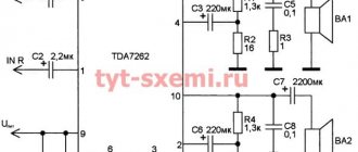
Schematic diagram of the VHF unit “Estonia-006-stereo”
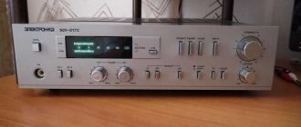
Warm tube sound as the norm of life: the best Soviet radios
The idea of a universal audio combine, which has everything you need to listen to records and radio broadcasts, is far from new: the peak of popularity of such devices occurred in the 60s and 70s of the twentieth century. We remember the best Soviet tube radios, which became an important part of the history of high-quality sound reproduction.
Rigonda-Mono
The Rigonda-Mono radio was produced at the Riga Radio Plant since 1963 and included a DV/SV/HF/VHF receiver, as well as a vinyl player, offering a decent price-quality combination for those times. The device was sold in huge quantities, becoming the people's “music center” for the inhabitants of the USSR. Output power - 3.5 “honest tube” watts: in combination with lightweight paper diffusers of standard speakers, this made it possible to sound a small or medium-sized room. Formally, the frequency range is very modest (from 60 to 12,000 Hz), but in reality the Rigonda-Mono sounded very pleasant and solid. A three-speed electric turntable with auto-stop is completely unremarkable, with a very simple tonearm. However, the connector for external sources offered a chance to correct the situation by connecting a good turntable of a higher class or a tape recorder to the radio.
Belarus R-101-L
The tube radio "Belarus R-101-L" was produced by the Minsk Radio Plant since 1966 and became a good alternative to the then popular "Estonia" and "Rigondam". The musical “combine” was equipped with a DV/SV/HF/VHF radio and a three-speed record player. The acoustic system is made on the basis of four 2GD-29 broadband speakers, which were installed on the front and side panels of the case - for more voluminous and solid sound. The amplification part is built on 6P14P tubes: a power of about 6 W was enough to fill a small or medium-sized room with sound. The radiola was equipped with legs and did not look very luxurious, but quite attractive: by today's standards, it could be considered middle-class audio equipment at an affordable price.
Rigonda-Stereo
A breakthrough device for its time, the Rigonda-Stereo stereo radio, was produced since 1963 at the Riga Radio Plant and did not become as widespread as its monophonic counterparts - not least because of its large dimensions and high cost of 230 rubles ( for this money you could buy a good TV). In addition, stereo broadcasting and stereo records were not yet very common. However, “Rigonda-Stereo” turned out to be a successful precedent for the subsequent active development of stereophony in the USSR. The acoustic systems were of an original design by modern standards: a pair of 4GD-28 speakers were installed on the front panel of each speaker, and 1GD-19 radiators were located on the left and right sides of the case. The radio turned out to be so successful that it was supplied abroad, in an export version under the name “Rigonda-Stereo” - with different inscriptions on the body, scale and back wall, as well as a VHF range of 88-104 MHz.
Estonia-3
Tallinn offered audio equipment that was very worthy for its time: the quality of serial production was noticeably above average, and the design was often extremely successful. The Estonia-3 radio, which went on sale in 1963, was no exception. The device consisted of a main block, which housed the radio receiver and vinyl player itself, as well as a floor-standing speaker system (with a pair of 4GD-7 broadband speakers) and two satellites with 1GD-9 emitters installed in them. The radiola was supplied in monophonic or stereophonic version: in the second case, with a stereo attachment and a corresponding pickup. Such luxury cost a lot: 299 rubles - a significant amount by the standards of the 60s.
Symphony-2
The radio "Symphony-2" was produced by the Riga Radio Plant named after. A.S. Popov since 1967 and, unlike the earlier Rigonda-Stereo model, allowed you to listen to radio broadcasts in stereo right out of the box. In addition, the standard acoustic systems were modified, which are already quite similar to modern floor-standing speakers: a three-way configuration with speakers that were very decent for their times, a closed box design with two additional compartments (Helmholtz resonators), which communicated with the main volume of the body through holes of a given diameter and optimized the sound in the low frequency range.
In addition to a radio receiver with an automatic frequency adjustment function, Symphony-2 was equipped with a simple three-speed vinyl player (fortunately, there was an input on the back wall for connecting a higher-quality turntable or tape recorder). The push-pull stereo amplifier is built on 6P14P pentodes: the output power is 4 “honest tube” watts per channel, which made it possible to confidently “boost” standard speaker systems with lightweight paper speakers. This model was supplied both for the domestic market and for export.
Estonia-Stereo
In 1970, shortly after the launch of the production of the Symphony-2 stereo radio at the Riga Radio Plant, it launched production of a similar model called Estonia-Stereo. The fundamental changes concerned, first of all, the design: unlike Symphony 2, the vinyl player was presented as a separate block. Thus, the device occupied less living space, and if desired, the turntable could be completely turned off and put away on the mezzanine (in the attic, on the balcony, in the pantry or in the garage - underline what is necessary). In addition, the design of the standard speaker systems was slightly different: instead of the 3GD-1 mid-frequency speaker, the Estonia-Stereo used a 4GD-28. Accordingly, the crossover design was somewhat different. The output power is “honest tube” 4 W per channel: paradoxically, this even made it possible to organize a small musical party - with drinks, dancing and more. The sound of the radiola is soft and vintage in every sense. But the main thing is the price: for “Estonia-Stereo” they asked for 420 rubles, which was comparable to several average salaries of a USSR citizen.
Symphony-003
Radiola “Symphony 003” was introduced by the Riga Radio Factory in 1971, already at the end of the era of tube sound. Compared to its predecessor “Symphony-2”, the updated model had a completely redesigned design: the compartment for the vinyl player “moved” down, and the standard speakers became slightly smaller in height and at the same time larger in depth. In technical terms, the device differed slightly from the previous version and offered approximately the same functionality: LW/MW/HF/VHF receiver with automatic frequency control, as well as a simple three-speed vinyl player and an input for connecting external sources (for example, a higher-class turntable or tape recorder) . A push-pull stereo amplifier with a power of only 2x4 W (but honest, warm and tube power) on 6P14P pentodes confidently drove three-way speaker systems with light paper bass drivers and high sensitivity. Like its predecessors, the Symphony-003 radiola was distinguished by a soft, comfortable sound and confidently filled a small or medium-sized room with sound.