- home
- →
- Radio engineering of the 19th and 20th centuries (TVs, acoustics, optics, etc.)
- →
- Acoustic systems, speakers, loudspeakers by USSR manufacturing plants
- →
- Acustic systems
- →
- post-war speaker systems
- →
- Radio engineering plant of the mountains. Riga
Description
Radiotehnika S-50B is a three-way speaker system with a bass reflex. Produced on Radiotehnika software in Riga.
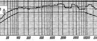
Designed for high-quality reproduction of music and speech programs in stationary living conditions. The recommended power of a high-quality household amplifier is 50 W. The preferred installation option is floor-mounted. The speaker body is made in the form of a rectangular non-demountable box made of chipboard, veneered with valuable wood veneer. At the joints of the housing walls on the inside there are elements installed that increase the rigidity and strength of the housing. The speaker heads are framed by two decorative overlays made of plastic and painted to resemble metal or without painting. One trim frames the HF and midrange heads, as well as the upper half of the front panel of the speakers, the other - the woofer head and the lower half of the front panel. The midrange head is isolated on the inside from the total volume of the housing by a plastic casing in the shape of a truncated cone. All heads are located on the front panel symmetrically relative to the vertical axis. At the top of the front panel there is a nameplate with the sound pressure frequency response curve and the name of the speaker depicted on it. In the upper right corner there is an indicator of speaker overload, and in the lower part there is a rectangular bass reflex hole, the tuning frequency of which is 37 Hz. The internal volume of the AC is 27 cubic dm. To reduce the influence on the frequency response of sound pressure and the sound quality of speakers from the resonances of the internal volume of the housing, it is filled with a sound absorber, which is a mat of technical wool covered with gauze. The mats are located and fixed on the inner surfaces of the housing walls. The design of the filters and the overload indication unit uses resistors such as BC, MLT, SPZ-38B, S5-35V, capacitors such as K73-11, MBGO-2, K50-12 and inductors on plastic cast frames.
The speakers use the following heads: - LF 35GDN-1-8; — SCH 20GDS-1-16; — HF 6GDV-1-16; Technical characteristics: — Reproducible frequency range — 40-20000 Hz; — Uneven frequency response of sound pressure, at the lower limit frequency of the range relative to the level of average sound pressure — 8 dB; — Uneven frequency response of sound pressure, in the range of 100-8000 Hz — +-4 dB; — Level of characteristic sensitivity — 85 dB; — Nominal electrical resistance — 8 Ohms; — The minimum value of total electrical resistance is 7.5 Ohms; — Limit rated power — 50 W; — Maximum short-term power — 400 W; Size: 314x580x256 mm; Weight: 15 kg.
Modernization of the Radiotehnika S-50B speaker system
The acoustic system “Radiotekhnika S-50B” was produced by the Riga PA “Radiotekhnika” from the first quarter of 1982 [1]. At the time of release, the system was a fairly high-quality example of an acoustic system (AS), which was equipped with domestic radio equipment.
The schematic diagram of this speaker is shown in Fig. 1. According to the diagram, the passive crossover of the speaker is made using second-order filters. Quite a lot has been written in the literature about the influence of the order of filters on the operation of dynamic heads, and most authors note the greater efficiency of using filters of a higher order.
To prove this, they provide graphs of measurements of AHF columns and delightful statements about the quality of their work. However, the results of subjective expert listening to speakers using first-order filters do not always confirm this.
Unfortunately, instrumental measurements of the characteristics of speakers in an anechoic chamber do not allow us to fully assess their quality. Expert listening is a necessary element of the assessment. The literature [2, 3] provides descriptions of the use of series filters in a crossover, allowing a different look at the formation of loudspeaker frequency bands. This method has a number of advantages that improve sound quality.
To test this solution, the “Radiotekhnika S-50B” acoustic system was modernized. For this purpose, two functional speakers were taken, the difference in sound of which was practically absent. The effectiveness of the changes made was checked by comparing the results of listening to the converted speaker with the control one. During the tests, the modernized amplifier “Radiotekhnika U-7101” was used [4]. Additionally, changes have been made to the configuration and design of some speaker elements.
The diagram of the modernized version of the speaker (indication board is not shown) is shown in Fig. 2. As can be seen from the diagram, the dynamic head 6GDV-1 was replaced with an isodynamic head 10GI-1-4. This head has more advanced technical characteristics and greater power [5].
The use of a series filter allows you to combine heads with different nominal resistances in different bands [2]. This property turned out to be very useful in this situation.
Correction of the HF return is carried out by selecting resistor R1. The 20GDS-1 mid-frequency head had many complaints about sound quality. Many authors have proposed many ways to improve it. The use of tennis balls and re-gluing of the dust cap did not lead to significant changes in sound. But it became obvious that the low rigidity of the cap was one of the reasons for the complaints.
Therefore, the modification began with this - the dust cap was covered with two layers of celluloid dissolved in acetone. At the same time, the rigidity of the cap increased significantly; in fact, the dome was reinforced. Next, a horn of a suitable size was glued onto the dome of the cap, which somewhat improved the sound of the head at frequencies above 4 kHz.
The return of the heads is affected by the residual magnetization of the installed magnets. To test the effectiveness of introducing an additional magnet, two dynamic heads were fastened with diffusers towards each other. A signal from the AF generator was supplied to one of the heads, and the second head was connected to a millivoltmeter. By installing an additional magnet in the required polarity to the main magnet, you can see how effective the additional magnetic field will be.
In the head I tested, the output increased by 2 dB. Further increasing the number of magnets had no effect, so only one magnet was glued to the main magnet. The general view of the modified midrange head is shown in Fig. 3.
On low-frequency heads, this operation did not reveal the need for additional magnets. After dismantling the unnecessary elements, the parts of the new crossover are placed on its previous board (the numbering of the elements has been changed).
In accordance with the new crossover circuit (see Fig. 2), only capacitor C1 6.8 μF for a voltage of 160 V (K73-11) and coil L2 with an inductance of 0.3 mH have been added; everything else was already on the board. In addition, the values of powerful resistors (R1) were changed to equalize the output of the RF heads. In Fig. Figure 4 shows the upgraded filter board installed in the column.
The volume of sound-absorbing material has been increased in each housing by 50%, and in the midrange head shell by 70%. The count was made from the factory settings of the absorber. The sound absorber present in the housing (cotton wool in a mesh) is concentrated in the upper part of the speaker, and the additional one is rolled up into a rag mat and placed on the rear wall behind the woofer head. The HF head is rotated 90° relative to the recommended one due to the need to fit into the appearance of the decorative panel with a grille.
If this is not done, then part of the slot holes of the emitter will be covered by the panel. In this case, you will have to make changes to the panel design, which is very difficult. I listened to both options for the head location and, without noticing any noticeable changes in the radiation pattern, accepted the option of a horizontal arrangement of the head slots.
An additional horn in the midrange head and optimization of the location of the speakers make it possible to mitigate the contradiction, but do not exclude the use of the option recommended by the manufacturer.
Practically, the markings for installing the head were carried out as follows. From the upper point of the midrange head contour circumference, 4 mm is set aside upward and a line is drawn, which is the lower boundary of the HF head installation. Next, the remaining marking lines are drawn according to the dimensions of the head perimeter and the hole is cut out. The head is fastened using two legs, which tighten it when tightening the screws.
The tightness of the installation is ensured by a seal located along
the perimeter of the rear panel of the emitter. The sealant is a rubber tube with an adhesive strip, which is used to seal doors and windows. The same seal is used when installing the remaining heads. The process of completing the installation of heads is shown in Fig. 5.
Some changes have been made to the design of the decorative panel and the grille of the MF-HF emitter group. They are necessary to hide traces of the round hole of the previous head and organize a horn for the new one. The reverse side of the decorative panel with the changes made is shown in Fig. 6. The general view of the completed product is shown in Fig. 7.
The results of a practical comparison of the two speakers showed a clearly visible advantage of the modernized version. The sound has become more prominent, and the impulse characteristics have improved. His great emotional detail became apparent. The joining of bands, attacks in the sounds of musical instruments and timbres - everything has changed for the better.
Modernization of Radiotehnika S-50B
The Radiotekhnika S-50B acoustic system was produced by the Riga Radiotekhnika Production Association from the first quarter of 1982. At the time of its release, the system was a fairly high-quality example of an acoustic system (AS), which was used to equip domestic radio equipment.
Rice. 1. Schematic diagram of S-50B
According to the diagram, the speaker's passive crossover is made using second-order filters. Quite a lot has been written in the literature about the influence of the order of filters on the operation of dynamic heads, and most authors note the greater efficiency of using filters of a higher order.
To prove this, they provide graphs of measurements of AHF columns and delightful statements about the quality of their work. However, the results of subjective expert listening to speakers using first-order filters do not always confirm this.
Unfortunately, instrumental measurements of the characteristics of speakers in an anechoic chamber do not allow us to fully assess their quality. Expert listening is a necessary element of the assessment. The literature contains descriptions of the use of series filters in a crossover, allowing a different look at the formation of loudspeaker frequency bands. This method has a number of advantages that improve sound quality.
To test this solution, the Radiotekhnika S-50B acoustic system was modernized. For this purpose, two functional speakers were taken, the difference in sound of which was practically absent. The effectiveness of the changes made was checked by comparing the results of listening to the converted speaker with the control one. During the tests, the modernized amplifier “Radiotekhnika U-7101” . Additionally, changes have been made to the configuration and design of some speaker elements.
The diagram of the modernized version of the speaker (indication board is not shown) is shown in Fig. 6 GDV-1-16 was replaced with the isodynamic head 10 GI-1-4 . This head has more advanced technical characteristics and greater power.
Using a series filter allows you to combine heads with different nominal resistances in different bands. This property turned out to be very useful in this situation.
Correction of the HF return is carried out by selecting resistor R1. The mid-frequency head 20 GDS-1-16 had many complaints about the sound quality. Many authors have proposed many ways to improve it. The use of tennis balls and re-gluing of the dust cap did not lead to significant changes in sound. But it became obvious that the low rigidity of the cap was one of the reasons for the complaints.
Therefore, the modification began with this - the dust cap was covered with two layers of celluloid dissolved in acetone. At the same time, the rigidity of the cap increased significantly; in fact, the dome was reinforced. Next, a horn of a suitable size was glued onto the dome of the cap, which somewhat improved the sound of the head at frequencies above 4000 Hz.
The return of the heads is affected by the residual magnetization of the installed magnets. To test the effectiveness of introducing an additional magnet, two dynamic heads were fastened with diffusers towards each other. A signal from the AF generator was supplied to one of the heads, and the second head was connected to a millivoltmeter. By installing an additional magnet in the required polarity to the main magnet, you can see how effective the additional magnetic field will be.
Installing mid-range speakers. In the head I tested, the output increased by 2 dB. Further increasing the number of magnets had no effect, so only one magnet was glued to the main magnet. The general view of the modified midrange head is shown in Fig. 3.
On low-frequency heads, this operation did not reveal the need for additional magnets. After dismantling the unnecessary elements, the parts of the new crossover are placed on its previous board (the numbering of the elements has been changed).
In accordance with the new crossover circuit (see Fig. 2), only capacitor C1 6.8 μF for a voltage of 160 V (K73-11) and coil L2 with an inductance of 0.3 mH have been added; everything else was already on the board. In addition, the values of powerful resistors (R1) were changed to equalize the output of the RF heads. In Fig. Figure 4 shows the upgraded filter board installed in the column.
The volume of sound-absorbing material has been increased in each housing by 50%, and in the midrange head shell by 70%. The count was made from the factory settings of the absorber. The sound absorber present in the housing (cotton wool in a mesh) is concentrated in the upper part of the speaker, and the additional one is rolled up into a rag mat and placed on the rear wall behind the woofer head. The HF head is rotated 90° relative to the recommended one due to the need to fit into the appearance of the decorative panel with a grille.
If this is not done, then part of the slot holes of the emitter will be covered by the panel. In this case, you will have to make changes to the panel design, which is very difficult. I listened to both options for the head location and, without noticing any noticeable changes in the radiation pattern, accepted the option of a horizontal arrangement of the head slots.
An additional horn in the midrange head and optimization of the location of the speakers make it possible to mitigate the contradiction, but do not exclude the use of the option recommended by the manufacturer.
Practically, the markings for installing the head were carried out as follows. From the upper point of the midrange head contour circumference, 4 mm is set aside upward and a line is drawn, which is the lower boundary of the HF head installation. Next, the remaining marking lines are drawn according to the dimensions of the head perimeter and the hole is cut out. The head is fastened using two legs, which tighten it when tightening the screws.
The tightness of the installation is ensured by a seal located around the perimeter of the rear panel of the emitter. The sealant is a rubber tube with an adhesive strip, which is used to seal doors and windows. The same seal is used when installing the remaining heads. The process of completing the installation of heads is shown in Fig. 5.
Some changes have been made to the design of the decorative panel and the grille of the MF-HF emitter group. They are necessary to hide traces of the round hole of the previous head and organize a horn for the new one. The reverse side of the decorative panel with the changes made is shown in Fig. 6. The general view of the completed product is shown in Fig. 7.
The results of a practical comparison of the two speakers showed a clearly visible advantage of the modernized version. The sound has become more prominent, and the impulse characteristics have improved. His great emotional detail became apparent. The joining of bands, attacks in the sounds of musical instruments and timbres - everything has changed for the better.
Based on materials from: radiochipi.ru
