Hello, dear Datagorians! I share with you my own experience in mastering the Arduino UNO board and the Atmega 328 controller that is installed on it. This board was purchased a long time ago, and was quietly waiting its turn for some very first craft in the back drawer of my desk.
Arduino UNO R3 MEGA328P on Aliexpress
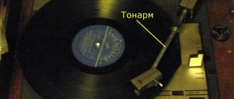
The line arrived unexpectedly. I have a vinyl player "Estonia 010", which is a fully automatic machine. I put on the record and pressed two buttons: “Network” and “Start.” The player will do the rest for you. Up to a certain point, the player worked, conscientiously performing its functions, when suddenly it stopped showing signs of life, completely refusing to move the tonearm and not responding to pressing the control buttons.
↑ Historical background
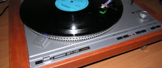
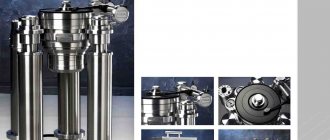
This is “Estonia 010”, which was produced by our industry in the 80s of the last century.
The characteristics are impressive. Nominal frequency range, Hz - 20...20000. Detonation coefficient, % - 0.08. Relative rumble level, dB -74. Dimensions, mm - 480x108x384. Weight, kg - 12. Like many other things (see the same TDS-5 headphones), this device is a slightly less successful Soviet copy of a foreign one, namely the SHARP Optonica RP-7100. For example, quartz stabilization of drive speeds, etc., is not implemented. And here is the prototype - Japanese Optonica.
Photos by Optonics - Gonchar, Moscow
When I opened the Estonia, an automation board appeared in front of me. And another scarf! It houses over 20 packages of Soviet logic chips and opamps. Seeing so many chips, I winced and threw the board out of the player. I really didn’t want to poke the oscilloscope probe into it.
I soldered two parts: the K155ID4 song indication decoder and a resistor for powering the infrared LED that is installed on the additional tonearm in the record pause detector.
Instead of the original filling, it was decided to try to adapt “that same Arduino” for control. And work... I’d be lying if I said it was boiling. The work began to gurgle lazily in the free time for gurgling.
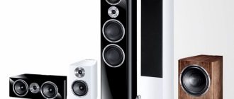
Electric player Estonia 010 Stereo
Produced since 1983 at the Tallinn plant Punan-RET.
The Estonia UM-010S stereo power amplifier is designed to amplify 3F signals coming from the same type or other AF preamplifiers. The PA has LED indicators of operating modes, electronic overload protection, stereo telephones, and two pairs of speakers.
Specifications:
– Effectively reproduced frequency range: 20 – 25000 Hz
– Frequency response unevenness relative to 1000 Hz in the range 20-25000 Hz: ±0.4 dB
– Nominal output power per channel: 35 W/8 ohms
– Maximum output power per channel: 50 W/8 ohms
– Harmonic distortion in the range 40-16000 Hz: 0.03%
– Total Intermodulation Distortion Ratio: 0.06%
– Signal to weighted noise ratio: 105 dB
– Crosstalk attenuation between channels in the range 250-10000 Hz: 56 dB
– Power consumption from the network with an output of 2x10 W: 105 W
Size: 460x88x395 mm
Weight: 13 kg
↑ Scheme of modifications “Estonia 010” for Arduino UNO
We had to completely redo the keyboard circuit in order to save control inputs.
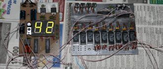
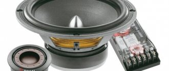
According to the new scheme, all buttons were placed on one bus, each through its own resistor. When pressed, the original buttons had some resistance and were incorrectly recognized, which did not suit either me or the Arduino. The buttons needed to be replaced, which was done by installing new tact buttons, which, unlike the old ones, also click nicely. Then, to link with the motor and tonearm solenoid, as well as with the optics of the sensor and to indicate the serial number of the song, the following circuit was assembled:
Fragment excluded. The full version is available to patrons and full members of the community.
We have three relays, an indication of their position, pull-up resistors of the limit switches, a song number decoder, and a KR544UD2 op-amp with trimming resistors to regulate the operating threshold and amplify the signal from the phototransistor.
Estonia UP-010-stereo, Symphony-2. Description of the electrical circuit
(Fig. 30): there is no resistor R21 shunting the first input circuit of the DV; there are resistors R22 and R23 cycles 10 and 9 (respectively) with the housing; no body amplification, powered by alternating current from a special winding of a power transformer;6) the radio power supply is slightly different in its electrical circuit (see diagram in Fig. 41). The wiring diagram of the power supply is not given, since it has undergone minor changes, which mainly affected the design of the power transformer (it has a smaller number of secondary windings). In addition, there is no additional rectifier with filter;
7) Structurally, the radio is made in the form of one common wooden floor case mounted on special legs. The left (larger) part of the case contains the receiver, and the right (smaller) part contains the PEPU-32S electric player. A power supply is mounted under the player on a special metal chassis. The player compartment is closed with a wooden lid. The remaining design solutions are identical to the corresponding solutions in the Symphony-003 radio. The functional diagram of the radio is practically no different from that shown in Fig. 28.
Rice. 41. Schematic diagram of the Symphony-2 power supply
5. “ESTONIA-STEREO”
The Estonia-stereo radio is a modernization of the Symphony-2 radio. Its circuit diagram has minor differences from the circuit diagram of the Symphony-003 radio, which basically boils down to the following:
1) the extended short-wave ranges KBIII (41.1-55.0 m) and KBIV (55.0-79.0 m) have been changed, for which the circuit of the input, heterodyne and UHF circuits has been redone, and the parameters of the loop coils have also been changed;
2) the switching of the “Stereo” (B 11) and “Pickup” (B10) circuits has been simplified;
3) the suppression of signals with a frequency equal to the intermediate one is enhanced by changing the filters L34, C21 and L21, C32. The schematic diagram of the KSDV block is not given, since the KSDV block of the Estonia-006 radio is made according to the same scheme (see Fig. 44);
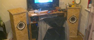
4) to improve sound quality, the connection diagram for loudspeakers in sound speakers was changed by connecting loudspeaker Tr2 through autotransformer A Tr (see Fig. 36, b);
5) each sound column has three loudspeakers: low-frequency 6GD-2 with a resonant frequency of 30 Hz, mid-frequency 4GD-28 with a resonant frequency of 90 Hz and high-frequency type 1GD-3;
6) the radio power supply circuit is different. Compared to the power supply circuit of the Symphony-003 radio (see Fig. 37), all changes boil down to the following: in the second primary winding of the power transformer there is no middle terminal; one secondary winding, intended for powering the stereo indicator of the LED block, is excluded (here the power is supplied from winding 13, 14); the filter of the additional rectifier consists of only one capacitor SJ. The schematic diagram of the power supply is shown in Fig. 42.
Structurally, the radio consists of four blocks: a receiver, an electric player and two sound speakers. The block design of the radio allows it to be successfully placed in modern furniture: walls and shelving. The IEPU-32S electric player is installed in a separate case and is connected to the receiving part using a unified SG5 connector. The EPU is powered from an alternating current network of 127 or 220 V through a special autotransformer (A Tr).
In the same case there are also installed a network voltage switch “B'” of type PNS-1-2, a turntable switch (B18) of type VK-2, a fuse in a special block and a JIH8 light bulb, signaling the switching on and off of shoving.
Rice. 42. Schematic diagram of the Estonia-Stereo power supply
The remaining design solutions do not differ from the corresponding solutions in the Symphony-003 radio. The functional diagram of the receiving part of the radio is similar (taking into account changes in the KSDV block) shown in Fig. 28.
6. "ESTONIA-006"
The functional diagram of the radio is shown in Fig. 43. Compared to the Estonia-stereo radio scheme, it has undergone significant changes, which mainly boil down to the following: automatic frequency adjustment has been introduced in the FM and AM bands; The stereo bass amplifier has been completely redesigned, which is made using transistors; The stereo decoder block circuit has been partially changed; as a speaker system
unified sound speakers of type 10MAS-1 or 10MAS-1M were used; it is possible to connect stereo headphones using a special socket; The power supply circuit has been changed; an electric player of the PEPU-52S type has been installed; The external design of the radio has been improved.
In Fig. 44 shows the schematic diagram and the color insert shows the wiring diagram of the KSDV unit. Need to
It should be noted that the schematic diagram of this block differs only slightly from that shown in Fig. 30. The schematic diagram of the inverter unit is similar to that shown in Fig. 31, except that an additional pin 19 is introduced on the board. Using this contact, in addition to capacitor C30, capacitor C56 is connected to the second circuit of the filter AM FPCH1U (pin 3) when operating in the MV range or capacitor C58 when operating in the DV range. When the magnetic antenna is turned on, capacitor C57 is connected. These capacitors are installed in the KSDV block. Pin 10 of the inverter board is not used and is connected to the housing. In addition, a capacitor C38 is connected between pins 11 and 12 of the IF board. The wiring diagram of the printed circuit board of the IF unit corresponds to the diagrams of “Symphony-2”, “Symphony-003” and “Estonia-stereo” shown on the color insert.
The VHF radio unit is assembled according to the same scheme as in the Symphony-003 radio. but instead of a 6Zh1P (JI2) lamp, a 6Zh5P lamp was used and automatic frequency control was introduced. The block diagram is shown in Fig. 45. To implement AFC in parallel -
↑ About setting up the keyboard
Even if we take the resistors indicated here strictly at their nominal value, it will be difficult to get into the range specified in the program, therefore, having been somewhat confused with the calculations of the values that need to be written in the sketch for this or that button (and resistor), I went a different way. I uploaded an auxiliary sketch to Arduino.