Standards 1DIN and 2DIN
The differences between them are the height of the radios. The number 2 in the designation of the 2DIN standard indicates that the height of a double-DIN receiver is 2 times greater than a device made according to the 1DIN standard. The latest radios are now the most popular and widespread. Installation of double-din radios is not possible in every car, since an appropriate seat must be provided on the front panel.
All car radios are divided into two types: with a proprietary connector, most often made in the form of a plug, and located on the rear wall, and with a universal ISO connector. In the first case, you should purchase a proprietary connector for the radio, the pinout of which matches the desired model. If the machine has an ISO socket, then the other end of the proprietary cable should also have an ISO plug. In the second case, the radio is connected directly to the ISO socket located in the car.
When replacing the radio with another one, you should look at the back wall and determine which block is located there. After this, you can decide whether to purchase a proprietary plug or you can connect the device to the machine through an already installed ISO socket. The pinout of the car radio connector is carried out according to the ISO 10487 standard.
How to properly connect to an electronic device
The concept of an interface as we know it today dates back to the 1960s. More precisely, in 1964, when the company developed its legendary IBM System/360 mainframe. It was then that the main tasks of any interface - physical or virtual - were formulated. They were to provide a standard connection for all devices.
Euro connectors
Initially, only a few types of standard inputs could be made to ensure compatibility between products from different manufacturers. This was a PS/2 port for the keyboard, an LPT port for the printer, and a connector for the PCI card. Nowadays, each type of connection has its own standard interface; this approach greatly simplifies the development and sale of any type of device and allows you to understand their built-in capabilities. Here are descriptions of the main communication elements, first of all, the designation of the button on the radio, which are used on the panels of Pioneer and other car radios.
Description of the buttons on the front panel of the radio for control (decoding)
| Button labels | Button function |
| A.F. | Different RDS frequency, automatic search when reception is poor |
| ALL OFF | Everything is off |
| AMS | Music sensor, works on the principle of playing a number of tracks equal to the number of clicks |
| ANG | Panel adjustment |
| ATA | The radio turns on automatically when you turn off and rewind media tracks |
| A.T.T. | Quickly reduces volume |
| BAND | Selecting a radio receiver |
| BEER | Enabling sound when pressing buttons |
| Blank Skip | Skips pauses longer than 8 seconds |
| BMS | Compensates for low frequencies when dropped due to the main device |
| BTM | Remembers the quality frequency of strong stations |
| CLK ADJ | Adjusts time |
| COLOR | Color |
| DISP | Display activation |
| DNPP | Selecting a CD in the changer |
| DNPS | Entering disc names |
| DSP | Activating the sound processor |
| EJECT | Remove the cassette from the cassette receiver or disc |
| EON | Reception of traffic information |
| FUNCTION | Switches the most used functions |
| INTO SCAN | Plays the recording for 10 seconds to search |
| LOS | Looks for stations, skipping with weak reception |
| LOUD | Tone compensation |
| M.RDM | Disc random playback |
| P.I. | Automatic search |
| PI SOUND | Switching to another frequency |
| PI MUTE | Muffled sound |
| POWER | Shutdown |
| PS | Listening to saved settings |
| PTY | Selecting a genre |
| RDS | Search for a station by metadata |
| RDM | Play disc tracks in any order |
| REG | Switching to the frequency of a radio station with RDS |
| Repeat Play | Replaying a track |
| SCAN | Scanning tracks and playing the beginning |
| SEL | Settings |
| SHUFFLE PLAY | Play available music in random order |
| SYSTEM Q | Tracking sound enhancement factors and showing them on the display |
| TA SEEK | Searching for a station with RDS |
| TC | Calling the tuner when rewinding |
ISO pinout
Many new radios increasingly use a Euro connector. It is a rectangular sixteen-pin plug consisting of one or two equal parts. An ISO plug is installed on the car, allowing you to connect any car radio that has the appropriate connector. The ISO pinout does not depend on the radio model equipped with such a connector.
Upper power connector A
It is used to supply current from the vehicle's on-board network, as well as to remove power from an active antenna or amplifier, to mute the sound and supply a backlight control signal. According to the standard, wires are marked by color:
- yellow - direct connection to the vehicle’s battery; it also supplies power to the receiver’s RAM, which provides storage of settings specified by the user;
- red - it supplies the main power;
- black is ground, the negative pole connected to the GU body;
- blue with a white stripe - when the car player is turned on, 12 V is supplied to the active antenna amplifier or the remote control controller of the car audio power amplifier;
- orange - a signal is sent to it from the vehicle’s side light switch to control the backlighting of the keys and display;
- brown - used to mute the sound, for example, while talking on the phone.
It is worth considering that two power supply systems are used. In the first case, the yellow and red wires on the pinout are connected together. The power supply to the radio does not depend on the position of the ignition key.
If you leave the car player on without a protection timer, the car battery may quickly drain.
The second system involves connecting the red wire through the ignition switch, and the yellow wire directly to the on-board network. Thanks to this, the power supply to the radio is connected to the position of the key. When the ignition is off, you can remove or insert the CD. It also keeps the audio system's built-in clock running and saves settings such as sound settings and radio channels.
The pinout of the ISO connector of the radio, intended for power supply, is carried out as follows. Pins 1, 2 and 3 are reserved and are used by some head units to enable additional functions. Pin 4 is connected to the yellow wire, and pin 5 is connected to the blue/white wire. An orange wire is connected to pin 6. Pin 7 is connected to the red wire, and pin 8 is connected to the black wire. This connector is often painted brown.
Bottom speaker connector B
It is used to supply amplified sound from the car player to the speakers. The wires through which alternating current directly flows from the microcircuit are solidly colored, and the wires connected to ground have black stripes. Color marking is carried out as follows:
- the white wire connects to the left front speaker;
- the gray wire connects to the right front speaker;
- the green wire connects to the left rear speaker;
- The purple wire connects to the right rear speaker.
Five-pin plug (ONTs-VG).
To disassemble the ONTs-VG plug, you need to press the tab with a screwdriver and remove the protective cap.
Don’t forget to put a protective cap on the cable and pieces of insulating tube (cambric) on the wires.
It is more convenient to solder the wires to the plug if you secure the latter with a clothespin, which, in turn, is pressed down to the table with something heavy.
Solder three wires one by one to the connector contacts.
It should look something like this.
The protective tubes can now be put on.
The arrow shows the cable fastening element, which does not allow securely fastening a thick cable.
If the cable is thick enough, and such cables are preferable when the connection length is several meters, then to securely fasten the cable you need to tightly wind 10-12 turns of thread in the place indicated in the picture.
To prevent the fastening from loosening while tying a knot, you can secure the ends of the thread with a drop of melted rosin.
We assemble both halves of the connector and align the hole in the protective cap with the fixing tab.
We put the cap on so that the fixing tab fits into the hole and secures the cap. If fixation does not occur, remove the cap and bend the tab up. We put the cap on again.
Pinout diagrams for radio tape recorders from popular manufacturers
Wiring of linear outputs on a standard radio can be done using two RCA connectors. This option is the most common, since power amplifiers have the same sockets. The pinout of connectors for Pioneer car radios contains from 10 to 20 contacts. Their purpose depends on the model of the multimedia device. For example, in the KEH series, the first pin is the antenna control, the second pin is the voltage from the ignition switch, etc. The speakers are connected to pins 3, 4, 5, 6, 8, 9, 10 and 11.
Many motorists are faced with the need to replace the head unit. The process requires a radio pinout and a guide for connecting the audio system.
Soldering iron.
A soldering iron with a power of 25 - 40 watts is suitable for soldering connecting audio cables.
The pictures show the process of preparing two tips with diameters of 4 and 6 millimeters for operation.
In some cases, you may need to use a file to correct the shape of the soldering iron tip.
A properly sharpened soldering iron tip is convenient not only for soldering, but also for removing insulation.
The tip of a 40-watt soldering iron with a diameter of 6 mm, for ease of use, can be slightly narrowed with a file.
After the tip has acquired the required shape, it must be burned so that the oxide prevents the solder from spreading beyond the working area. For firing, just turn on the soldering iron for 20 - 30 minutes.
Now you need, with the soldering iron still turned on, to pass the file along the working surface of the tip several times to remove the oxide. Immediately after this, you need to immerse the tip in rosin, rub the solder ball with the tip and immerse it in rosin again.
Your soldering iron is ready to go.
Pinout of a standard Euro connector
The Euro connector is a standard plug for many modern devices. An ISO plug is installed on the machine, thanks to which it becomes possible to connect any model of radio with the appropriate connector.
Standards 1DIN and 2DIN
The difference between the standards lies in the size of the devices: a 2-din device is 2 times higher than a 1-din device.
The most common are 1-DIN radios, because Installation of higher devices due to the lack of a seat of appropriate size on the front panel of the car is not possible in every car.
There are 2 types of radio tape recorders:
- With proprietary connector. You need to choose a product whose pinout matches the desired car.
- With universal connector. The device connects directly to the ISO socket provided in the car.
Pinout is carried out according to ISO 10487 standard.
Upper power connector A
The connector serves as a connector between sources and consumers of electricity from the on-board network.
Plugs 1, 2, 3, 6 are rarely used in radio circuits of the lower and middle price segments. The elements are used when connecting additional options in higher quality player models. Wire colors may vary.
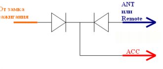
You should understand the purpose of the contacts:
- ANT. Used with a retractable antenna.
- Remote. Designed for connecting external amplifiers. Thanks to it, you can increase the number of mounted speakers, which is necessary in the interiors of large cars.
- Illumination. Adjusts the brightness of the player screen (the higher the driving speed, the less intense the backlight, so as not to distract the driver).
- Mute. Adjusts the sound of the device.
- A4. Turns the audio system on and off.
This connection scheme allows you to protect the battery from discharge, because turning on the system is possible only when you turn the ignition key, while the acoustic cascades consume electricity even when turned off.
The pinout of the ISO connector of the radio (European) looks like this:
- Connector A5 (blue) is for the antenna. If the permissible current value (300 µA) is exceeded, both the amplifier stages and the entire head unit may break.
- Wire A7 (red) is intended to power the head unit. When it is disabled, the settings are returned to factory settings. Voltage - 12 V.
- Cable A8 (black). Responsible for connecting the speaker system to the car.
To protect the audio system, the wires must be equipped with a fusible link. If interruptions occur in the operation of the player, you should place a capacitor between connectors A7 and A8, which will act as a filter, smoothing out fluctuations in the electrical circuit.
Bottom speaker connector B
The speakers are connected through it as follows:
- Rear right + (purple).
- Rear right - (black and purple).
- Front right + (gray).
- Front left - (black and gray).
- Front left + (white).
- Front left - (black and white).
- Rear left + (green).
- Rear left - (black and green).
Most devices are designed for 4 channels; 8 wires are used for this (2 pieces per speaker).
The sound quality of the system depends on the “flattening”. If you mix up the connectors, the device will not fail, but the radio will not work correctly.
Audio system elements should be connected with cables with a cross-section of 1.5 mm or more. Thicker wires are used on power lines.
Round connectors [ edit | edit code ]
All pin connectors (plugs) from this family have a metal jacket with a diameter of 13.2 mm with a protrusion (“key”) that specifies the orientation when connecting the plug to a socket. A number of connectors of a similar shape differ only in the configuration of the pins and are standardized in the documents DIN 41524 (three- and five-pin), DIN 45322 (6-pin at 60°), DIN 45326 (8-pin), DIN 45329 (7-pin) and other standards for various applications.
The plugs consist of a cylindrical metal skirt that protects several straight, round pins. The skirt is keyed to ensure that the plug can only be inserted into the socket in one position and to protect the contacts from damage. The basic design also ensures that the shield of the plug and socket is connected before all other contacts. However, because the key location is the same for all connectors, the key does not prevent incompatible connectors from being connected, which could cause damage. The situation has changed with Mini-DIN connectors, which have different keys on different types of connectors.
There are seven common layouts with a number of pins ranging from three to eight. There are three different five-pin connector types, with angles of 180°, 240° and 270° between the first and last pins (see illustrations above). There are also two options for seven-pin and eight-pin connectors: 360° and 270° [1]. There is some limited compatibility. For example, a three-prong plug will fit into any five-prong 180° socket and engage three prongs, leaving the other two unconnected. A 180° five-pin plug will fit into a seven- or eight-pin socket. Some high-end equipment used seven-pin connectors in which the two outer pins carried digital system data [2]: if the connected equipment was incompatible, the two outer pins could be removed from the plug so that they fit into standard five-pin 180° sockets without connecting data lines .
Screw-locking versions of these connectors have also been used in instrumentation, production control and professional audio applications [3] . In North America, this type is often called a “small Tuchel” connector, after one of the major manufacturers. Tuchel is now a division of Amphenol. The pin layout is almost the same as non-latching connectors, and in some cases, non-latching and non-latching connectors can be connected to each other. Additional configurations of up to 24 pins in the same shell are also available. In the 1980s, portable tape recorders and voice recorders sometimes used a bayonet-mounted version.
Pinouts for various brands of cars and radios
The wiring of the linear outputs on the standard radio depends on the make of the car and the head unit.
Before pinouting the connectors of the car radio, you must read the information presented on the cover of the device and in the instructions for it.
Toyota
For a standard plug: 1 - A+, 2 - GND, 3 - BAT+, 4 - backlight, 5 - antenna adjustment, 9-16 - speakers (RR+, RR-, RF+, RF-, LF+, LF-, LR+, LR -).
Universal connector for most models: 1 - ANT, 3 - linear output LR, 4 - GND linear outputs, 5 - linear output RR, 6 - CD in LCH, 7 - CD in GND, 8 - CD in RCH, 9 - CD reset , 10 — CD clock out, 11 — CD DSPL select, 12 — CD data out, 13 — CD clock in, 14 — CD data in, 16 — A+, 17 — GND, 18 — ANT GND, 22-27 and 29- 30 — speakers (LF-, LR+, RF-, RR+, LF+, LR-, RF+, RR-), 28 — CD mute, 31 — ANT CONT, 32 — CD ACC CONT, 33 — AMP CONT, 34 — B UP .
How to determine plus and minus on a speaker
In heavily worn, dubious speakers and loudspeakers, polarity information may be missing. In this case, the polarity of the speakers is determined using simple experiments.
Multimeter
The speaker impedance is low (from 2 to 4 ohms). It can be checked with a multimeter, but it rings equally in both directions. However, when connecting the red (positive) probe to the “+” speaker, the negative (black) probe to the “minus” speaker, the diffuser will move slightly forward (towards the listener). This movement is best determined by touch with your finger rather than visually.
Using a battery
When connecting the plus of the battery to the + of the speaker, the minus of the battery to the minus contact of the speaker, the cone will also move frontally, along which the speakers can be phased. Even if you phase all the speakers in reverse polarity, the sound quality will be the same as in direct polarity. The main thing is that all speakers work in the same phase. The battery should be connected for a short time (one or two seconds), otherwise you can “burn” the speaker.
Video - how to find out the polarity of the speaker:
Under no circumstances should you check the polarity of speakers and speakers using a car battery or charger. Even a short-term connection of the speaker to the battery can damage it.
Using a battery and a sheet of paper
Sometimes (for example, in a speaker) the speaker cone is covered with mesh or fabric. In this case, you can put a light sheet of paper on its surface. When voltage is applied, the sheet of paper will move forward or backward due to the sound pressure of the air. By the direction of movement one can judge the polarity.
Adapters for different connectors
The elements are designed to connect the car radio to the car's electrical network using various plugs. Often, adapters are equipped with ISO connectors on one side, and on the other, a non-standard proprietary connector suitable for a particular car model.
Using such elements, you can mount speaker systems with Euro connectors instead of devices with original plugs, and there is no need to re-solder the conductors or any other intervention in the machine’s electrical network. On sale you can find products with 2 non-standard plugs.
Sometimes the car is not equipped with connectors, then you need to connect the plug suitable for the radio to the wires in the car. This is done both by twisting and soldering. A terminal block is also used for this purpose; additional insulation is not needed in this case. When twisting and soldering, you will have to use cambrics or heat-shrink tubing to ensure safe use of the device.
Adapters are used to connect:
The advantage of using the elements is that there is no interference with standard wiring: the user does not have to solder or cut wires.
On devices with the option of control from the steering wheel of the car, a button adapter is provided - another type of adapter. It is a special device with which you can replace the standard audio system with other equipment.
Installation of a 3.5mm Jack type plug.
On the market you can find inexpensive 3.5mm Jacks, whose pads intended for soldering are coated with nickel. Rosin and flux based on it are not suitable for soldering them. If you do not have active flux, you will have to use a sharp knife or scalpel to remove the coating from these areas and then tin them in the usual way.
When connecting a Jack plug to a thick shielded cable, you need to take into account that there is not much space under the Jack's protective cap.
The picture shows that the screen cores are twisted asymmetrically with respect to the cable wires.
As in the case of the previous connector, do not forget to first put the protective cap on the cable.
The wire formed by the twisted conductors of the screen should be shortened to avoid shorting it to the left channel.
Car radio installation steps
It is no secret that the battery is the main source of power for the on-board grid of a car, but a battery malfunction can lead to damage to the car radio. To prevent equipment failure, you need to know how to properly connect the device yourself. During installation of the system, do not allow the positive contact of the battery to touch the negative or the speaker terminal. Experts do not recommend powering the device with plus or minus from the cigarette lighter or ignition switch.
Before connecting the speakers, it is necessary to take into account that the system connection will be optimal only to the battery. Thanks to this, you will be able to rid your speakers of various interferences and speakers, and it will be possible to operate them at full power. To make the connection, it is better to use a short copper stranded cable; its cross-section should be at least four mm2. On this wire, if it goes to the speakers or amplifier (not important), you need to install a fuse, which should preferably be located 50 cm from the battery. The wiring should be installed away from energy consumers; the wires should not be twisted - first of all, they are connected to the speakers, and then to the radio.
Features of ISO connectors
Having a single ISO connector standard (electrical characteristics), many automakers, as well as audio equipment companies, can change its external shape at their discretion. That is, if you decide to replace an outdated Hyundai radio with a Mystery multimedia system, first of all, pay attention to the matching iso connection formats.
Also, when installing equipment, you can quite often encounter slight changes in the pinout colors of electrical cords from the standard pinout. Next, we will provide visual descriptions of the pinout of the ISO connector of a standard sample and for individual brands of sound-reproducing equipment (pinout of the ISO connector of the Prology 1715t radio, etc.). Judge for yourself how different they are from each other.
An alternative to ISO connectors are Fakra connections.