Typically, a computer power supply has 6 or 5 connectors: 4 (4 pin) for powering drives and 2 (6 pin) (AT) or 1 (20 pin) (ATX) for the motherboard.
Motherboard power connectors
AT motherboard power connectors
| P8 № | Signal | Color |
| 1 | Power Good | orange |
| 2 | +5V | red |
| 3 | +12V | yellow |
| 4 | -12V | blue |
| 5 | frame | black |
| 6 | frame | black |
№
| Signal | Color | |
| 1 | frame | black |
| 2 | frame | black |
| 3 | -5V | white |
| 4 | +5V | red |
| 5 | +5V | red |
| 6 | +5V | red |
ATX motherboard power connector
| № | Signal | № | Signal |
| 1* | +3.3 V | 11 | +3.3 V |
| 2 | +3.3 V | 12 | -12 V |
| 3 | Earth | 13* | Earth |
| 4 | +5 V | 14* | Power Supply On |
| 5 | Earth | 15 | Earth |
| 6 | +5 V | 16 | Earth |
| 7 | Earth | 17 | Earth |
| 8 | Power Good | 18 | -5 V |
| 9 | +5 V Standby | 19 | +5 V |
| 10 | +12 V | 20 | +5 V |
Drive power connector
| № | Signal | Color |
| 1 | +12V | yellow |
| 2 | frame | black |
| 3 | frame | black |
| 4 | +5V | red |
Pinout of wires by color: terminology
So, let's understand the meaning of the terms: phase and neutral and zero. The power system has a 3-phase structure, the voltage between any pair of phases is 380 V. To reduce the voltage to the standard 220 V, a 0 wire was created in residential installations. The phase voltage between the neutral core and the 380 V wire will be equal to the potential difference with the familiar number 220 V.
Color range of current-carrying conductors according to the PUE:
- red;
- brown;
- black;
- gray;
- white;
- pink;
- orange;
- turquoise;
- purple.
European color marking standard
This contains many wire colors, except for those few elements that are intended exclusively to designate neutral and protective wires:
- blue color and its shades - working neutral wire (neutral - N);
- yellow with a green stripe - protective earth (PE);
- yellow-green insulation with blue marks at the ends of the conductors - combined (PEN) conductor.
It is allowed to use conductors with green insulation with a yellow stripe for grounding, and for combined conductors blue insulation with yellow-green marks at the ends.
Welding with an inverter for beginners: how to learn how to make the correct weld, welding equipment
Keyboard connectors
Attention! Contacts are not numbered in a circle; pay attention to the number next to the contact.
| DIN5 | PS/2 | |
| № | Signal | Purpose |
| 1 | Clock frequency | Exit |
| 2 | Data line | Enter exit |
| 3 | Reset | — |
| 4 | Frame | Entrance |
| 5 | +5V | Entrance |
| Signal | Enter exit | |
| 1 | Data line | Enter exit |
| 2 | Not connected | Reserve |
| 3 | Frame | Entrance |
| 4 | +5V | Entrance |
| 5 | Clock frequency | Exit |
| 6 | Not connected | Reserve |
IEE 1394 layout on the motherboard
IEEE 1394 is a high-speed serial data bus. Various companies use the brands Firewire for Apple, i.LINK for SONY, etc. for its name. Apple had a hand in the development. At its core, the connector is similar to USB. This port, apparently, will not be widely used due to licensing payments for each chip for this port in favor of Apple.
USB cable connector
| № | Signal | № | Signal |
| A1 | Vcc | B1 | Vcc |
| A2 | Port0 data+ | B2 | Port1 data+ |
| A3 | Port0 data- | B3 | Port1 data- |
| A4 | GND | B4 | GND |
AC and DC circuits, tables: pinout of wires by colors, letters and numbers
In order to better understand the pinout of wires, we present to your attention tables that indicate the color and alphanumeric phasing, zero, and grounding in various electrical circuits.
AC electrical circuit DC electrical circuit
How to correctly report data for electricity: how to transmit, when and in what way
RJ-45 connector (for twisted pair connection)
(the cable is directed away from the viewer)
When connecting a computer to a hub, the “normal” layout is used. When cascading hubs or when connecting a computer to a computer (without a hub), the “uplink” layout is used at one end of the cable, and the “normal” layout at the other.
| № | Fine | uplink |
| 1 | brown | brown |
| 2 | white-brown | white-brown |
| 3 | green | orange |
| 4 | white-blue | white-blue |
| 5 | blue | blue |
| 6 | white-green | white-orange |
| 7 | orange | green |
| 8 | white-orange | white-green |
Computer power supply
AT format PSU connector pinout
Pinout of ATX power supply connector
Pinout of additional power connectors: ATX connectors, SerialATA (or simply SATA, for connecting drives and hard drives), Connectors for additional processor power, Connector for floppy drive, MOLEX (for connecting hard drives and drives):
Another variant:
Another option for PSU video cards:
- Read more about the pinout of computer power connectors here
Cable for connecting drives
Cores 10 to 16 are twisted - necessary to identify the drive.
The odd numbered contacts are the body.
| № | Enter exit | Signal | Meaning |
| 2 | Entrance | High/normal density | High/Regulatory Density |
| 4 | Entrance | Unused | Manufacturer Specification |
| 6 | Entrance | Unused | Manufacturer Specification |
| 8 | Exit | Index | Index Hole Identification |
| 10 | Entrance | Motor Enable 0 | Drive A motor: enabled |
| 12 | Entrance | Drive Select 1 | Activating drive B: |
| 14 | Entrance | Drive Select 0 | Activating drive A: |
| 16 | Entrance | Motor Enable 1 | Drive B motor: enabled |
| 18 | Entrance | Direction Select | Specifying the direction for the head |
| 20 | Entrance | Step | Impulse for head movement |
| 22 | Entrance | Write Data | Data recording |
| 24 | Entrance | Write Gate | Signal to overwrite data |
| 26 | Exit | Track 00 | The head is on the zero track |
| 28 | Exit | Write Protect | The presence of disk write protection |
| 30 | Exit | Read Data | Reading data |
| 32 | Entrance | Side Select | First or second side access |
| 34 | Exit | Drive Status | Drive ready |
Data connectors (Southbridge)
IDE (Integrated Drive Electronics)
It is correctly called – ATA/ATAPI – Advanced Technology Attachment Packet Interface, used to connect hard drives and drives.
SATA and eSATA connectors
The same thing, the only difference is in the shape of the connector, this is a data connector for connecting hard drives and drives.
DVD slim sata
DVD slim sata (mini sata standard pinout).
Cable for connecting IDE devices
| Contact | Enter exit | Signal | Meaning |
| 1 | Exit | Reset | Reset |
| 2 | — | GND | Frame |
| 3 | Enter exit | HD7 | Data line 7 |
| 4 | Enter exit | HD8 | Data line 8 |
| 5 | Enter exit | HD6 | Data line 6 |
| 6 | Enter exit | HD9 | Data line 9 |
| 7 | Enter exit | HD5 | Data line 5 |
| 8 | Enter exit | HD10 | Data line 10 |
| 9 | Enter exit | HD4 | Data line 4 |
| 10 | Enter exit | HD11 | Data line 11 |
| 11 | Enter exit | HD3 | Data line 3 |
| 12 | Enter exit | HD12 | Data line 12 |
| 13 | Enter exit | HD2 | Data line 2 |
| 14 | Enter exit | HD13 | Data line 13 |
| 15 | Enter exit | HD1 | Data line 1 |
| 16 | Enter exit | HD14 | Data line 14 |
| 17 | Enter exit | HD0 | Data line 0 |
| 18 | Enter exit | HD15 | Data line 15 |
| 19 | — | GND | Frame |
| 20 | — | KEY | Connector key (missing) |
| 21 | — | Reserved | Reserved |
| 22 | — | GND | Frame |
| 23 | Exit | IOW | Reading strobe |
| 24 | — | GND | Frame |
| 25 | Exit | IOR | Recording strobe |
| 26 | — | GND | Frame |
| 27 | Entrance | IOCHRDY | I/O Channel Ready |
| 28 | Exit | ALE | Address strobe |
| 29 | — | Reserved | Reserved |
| 30 | — | GND | Frame |
| 31 | Entrance | IRQ14 | Interrupt Request |
| 32 | Entrance | HIO16 | Sign of access to a 16-bit port |
| 33 | Exit | HA1 | Address line 1 |
| 34 | Enter exit | Reserved | Reserved |
| 35 | Exit | HA0 | Address line 0 |
| 36 | Exit | HA2 | Address line 2 |
| 37 | Exit | CS0 | Select Disc 1 |
| 38 | Exit | CS1 | Select disc 2 |
| 39 | Enter exit | ACTIV | Confirming drive selection |
| 40 | — | GND | Frame |
Timers (PWM)
Timer outputs: in the microcontroller, in addition to the regular computing core with which we work, there are also “hardware” counters that work in parallel with all the other hardware. These counters are also called timers, although they have nothing to do with timers: counters literally count the number of ticks made by the crystal oscillator, which sets the operating frequency for the entire system. Knowing the frequency of the oscillator (usually 16 MHz) you can determine time intervals with very high accuracy and do something based on this. What use are these meters to us? Out of the box, called Arduino IDE, we have several ready-made timer-based tools (time functions, delays, pulse length measurements, and others).
This article is about pins and outputs, so we’ll talk about them: each counter has two GPIO outputs. The nano (ATmega328p MK) has three counters, respectively, 6 outputs. One of the counters' capabilities is the generation of a PWM signal, which is output to the corresponding GPIOs. For nano these are D pins 5 and 6 (counter 0), 9 and 10 (timer 1) and 3 and 11 (timer 2). A separate lesson is devoted to the PWM signal, now let’s just remember that with its help you can control the brightness of LEDs, the rotation speed of motors, the heating power of the coils and much more. But you need to remember that the current limit of 40 mA has not gone away and nothing more powerful than LEDs cannot be powered from the pins.
Parallel interface
Centronics cable connector pin assignments
| 25 pin | 36 pin | Signal | Enter exit | Meaning |
| 1 | 1 | STROBE | Exit | Data readiness |
| 2 | 2 | D0 | Exit | 1 bit of data |
| 3 | 3 | D1 | Exit | 2 data bits |
| 4 | 4 | D2 | Exit | 3 data bits |
| 5 | 5 | D3 | Exit | 4 data bits |
| 6 | 6 | D4 | Exit | 5 data bits |
| 7 | 7 | D5 | Exit | 6 data bits |
| 8 | 8 | D6 | Exit | 7 data bits |
| 9 | 9 | D7 | Exit | 8 data bits |
| 10 | 10 | ACK | Entrance | Data reception control |
| 11 | 11 | BUSY | Entrance | The printer is not ready to receive (busy) |
| 12 | 12 | P.E. | Entrance | End of paper |
| 13 | 13 | SLCT | Entrance | Monitoring the Printer Status |
| 14 | 14 | A.F. | Exit | Automatic line feed (LF) after carriage return (CR) |
| 15 | 32 | ERROR | Entrance | Error |
| 16 | 31 | INIT | Exit | Initializing the Printer |
| 17 | 36 | SLCT IN | Exit | The printer is on-line |
| 18 | 33 | GND | — | Frame |
| 19 | 19 | GND | — | Frame |
| 20 | 20 | GND | — | Frame |
| 21 | 21 | GND | — | Frame |
| 22 | 22 | GND | — | Frame |
| 23 | 23 | GND | — | Frame |
| 24 | 24 | GND | — | Frame |
| 25 | 25 | GND | — | Frame |
| — | 15 | GND/NC | — | Housing/loose |
| — | 16 | GND/NC | — | Housing/loose |
| — | 17 | GND | — | Printer circuit board housing |
| — | 18 | +5V DC | Entrance | +5 V |
| — | 26 | GND | — | Frame |
| — | 27 | GND | — | Frame |
| — | 28 | GND | — | Frame |
| — | 29 | GND | — | Frame |
| — | 30 | GND | — | Frame |
| — | 34 | NC | — | Free |
| — | 35 | +5V DC/NC | — | +5 V/free |
Pinout features
When talking about the pinout of a USB connector, you need to understand the symbols indicated on the diagrams. It’s worth starting with the type of connector - active (type A) or passive (type B). Using an active connector, information can be exchanged in two directions, and a passive connector only allows it to be received. You should also distinguish between two forms of connector:
- F - "mother".
- M - "dad".
USB connector
First, a few words need to be said about the compatibility of the three versions of the interface. Standards 1.1 and 2.0 are completely similar in design and differ only in the speed of information transfer. If one of the parties in the connection has a higher version, then work will be carried out at low speed. The OS will display the following message: “This device is capable of running faster.”
With compatibility between 3.0 and 2.0, everything is somewhat more complicated. A device or cable of the second version can be connected to the new connector, and backward compatibility exists only for active type A connectors. It should be noted that the USB interface allows you to supply a voltage of 5 V to the connected gadget with a current of no more than 0.5 A. For the USB standard 2.0, the color layout from left to right is as follows:
- Red - positive contact of constant voltage of 5 V.
- White - data-.
- Green - data+.
- Black is the common wire or ground.
The connector circuit is quite simple, and if necessary, repairing it will not be difficult. Since version 3.0 has increased the number of contacts, its pinout also differs from the previous standard. Thus, the color scheme of the contacts is as follows:
- Red - 5 V+.
- White - data-.
- Green - data+.
- Black is common.
- Purple - welcome.
- Orange - reception+.
- Without color - earth.
- Blue—transmission-.
- Yellow - transmission+.
Micro and mini connectors
Connectors of this form factor have five contacts, one of which is not always used. Conductors of green, black, red and white colors perform similar functions to USB 2.0. The mini-USB pinout corresponds to the micro-USB pinout. In type A connectors, the violet conductor is shorted to the black, but in passive connectors it is not used.
These connectors appeared due to the entry into the market of a large number of small devices. Since they are similar in appearance, users often have doubts about whether the connector belongs to a particular form factor. In addition to some differences in dimensions, micro-USBs have latches on the back side.
Miniaturization of the connector had a negative impact on reliability. Although mini-USB has a large resource, after a fairly short period of time it begins to dangle, but does not fall out of the socket. Micro-USB is a modified version of mini-USB. Thanks to the improved fastening, it turned out to be more reliable. Since 2011, this connector has become a unified standard for charging all mobile devices.
However, manufacturers are making some changes to the scheme. Thus, the pinout of the micro-USB connector for charging the iPhone involves two changes compared to the standard one. In these devices, the red and white wires are connected to the black through a resistance of 50 kOhm, and to the white - 75 kOhm. There are also differences from the standard for Samsung Galaxy smartphones. In it, the white and green conductors are closed, and pin 5 is connected to pin 4 using a 200 kOhm resistor.
Knowing the pinout of different types of USB connectors, you can find and fix the problem. Most often, this is required in a situation where the “native” charger has failed, but the user has a power supply from a smartphone from another manufacturer.
Serial data transfer
Serial interface (RS-232) connector pin assignments
| DB9 | DB25 | Signal | Enter exit | Meaning |
| 1 | 8 | DCD (Data Carrier Detect) | Entrance | Data carrier detection |
| 2 | 3 | RXD (Receive Data) | Entrance | Received data |
| 3 | 2 | TXD (Transmit Data) | Exit | Transmitted data |
| 4 | 20 | DTR (Data Terminal Ready) | Exit | Terminal readiness |
| 5 | 7 | GND (Ground) | Frame | Signal ground |
| 6 | 6 | DSR (Data Set Ready) | Entrance | Modem readiness |
| 7 | 4 | RTS (Request To Send) | Exit | Transfer request |
| 8 | 5 | CTS (Clear To Send) | Entrance | Reset for transfer |
| 9 | 22 | RI (Ring Indicator) | Entrance | Ring indicator |
Pinout diagram
Assignment of micro-USB connector contacts - socket and plug
The USB (Universal Serial Bus) connector is a universal-purpose serial bus, the most common wired method of connecting external devices to a computer. This connector allows you to organize data exchange between a computer and a video camera, card reader, MP3 player, external hard drive, or smartphone.
USB cable pinout by color
The cable description indicates its default plug orientation. The pinout is determined by the outside. If it is necessary to describe the structure from the installation side, this fact must be noted in the technical documentation. Insulating areas are marked dark gray on the connector and light gray on the metal part of the housing.
We recommend reading: Connecting an electric motor from 380 to 220: diagrams and methods of connecting an electric motor with photos and videos
Purple markings are used on charging wires and DATA cables.
Pinout is necessary to identify a faulty line during repair. It indicates the purpose of a particular component.
USB 2.0 connector pinout
Since the physical plugs and sockets of early versions 1.1 and 2.0 do not differ from each other, we will present the wiring of the latter. Below is a diagram of the wiring of the plug and socket of the Type A connector:
Designations:
- A - nest.
- B - plug.
- 1 - power supply +5.0 V.
- 2 and 3 signal wires.
- 4 - mass.
In the figure, the coloring of the contacts is shown according to the colors of the wire, and corresponds to the accepted specification.
- Reobass circuit for PC
Now let's look at the wiring of the classic socket B.
Designations:
- A - plug connected to the socket on peripheral devices.
- B - socket on a peripheral device.
- 1 - power contact (+5 V).
- 2 and 3 - signal contacts.
- 4 - ground wire contact.
The colors of the contacts correspond to the accepted colors of the wires in the cord.
Technological structure of the USB 2.0 interface
Connectors related to products included in the specification group 1.x - 2.0 (created before 2001) are connected to a four-core electrical cable, where two conductors are power and two more are transmitting data.
Also, in specifications 1.x - 2.0, wiring of service USB connectors requires the connection of a shielding braid - in fact, a fifth conductor.
This is what the physical design of normal USB connectors belonging to the second specification looks like. On the left are the “male” type versions, on the right are the “female” type versions and the pinout corresponding to both options
Existing versions of universal serial bus connectors of the noted specifications are presented in three options:
- Normal – type “A” and “B”.
- Mini – type “A” and “B”.
- Micro – type “A” and “B”.
The difference between all three types of products lies in the design approach. If normal connectors are intended for use on stationary equipment, “mini” and “micro” connectors are made for use in mobile devices.
This is what the physical design of the connectors of the second specification from the “mini” series looks like and, accordingly, the label for Mini USB connectors - the so-called pinout, based on which the user makes the cable connection
Therefore, the last two types are characterized by a miniature design and a slightly modified connector shape.
Pinout table for standard type “A” and “B” connectors
| Contact | Specification | Cable conductor | Function |
| 1 | Power + | Red (orange) | + 5V |
| 2 | Data - | White (gold) | Data – |
| 3 | Data + | Green | Data + |
| 4 | Nutrition - | Black blue) | Earth |
Along with the execution of connectors of the “mini-A” and “mini-B” types, as well as connectors of the “micro-A” and “micro-B” types, there are modifications of the “mini-AB” and “micro-AB” type connectors.
A distinctive feature of such designs is the wiring of the USB conductors on a 10-pin pad. However, in practice, such connectors are rarely used.
Micro USB and Mini USB interface pinout table for type “A” and “B” connectors
| Contact | Specification | Cable conductor | Function |
| 1 | Power + | Red | + 5V |
| 2 | Data - | White | Data – |
| 3 | Data + | Green | Data + |
| 4 | Identifier | – | Host - device |
| 5 | Nutrition - | Black | Earth |
Connector diagram for USB 2.0
In the diagram you can see several connectors that differ from each other according to a certain characteristic. For example, an active (power) device is designated by the letter A, and a passive (connected) device is designated by the letter B. Active devices include computers and hosts, while passive devices include printers, scanners, and other devices. It is also customary to separate connectors by gender: M (male) or “male” is the plug, and F (female) or “female” is the connector socket. There are formats by size: mini, micro and without marking. For example, if you see the designation “USB micro-VM”, this means that the plug is designed to connect to a passive device in micro format.
We recommend reading: All about bipolar transistors: principles of operation and mode of operation, switching circuits and methods of testing for functionality
To pin out sockets and plugs, you will need knowledge about the purpose of the wires in a USB cable:
- The red VBUS (“plus”) carries a constant voltage of 5 Volts relative to GND. The minimum electric current value for it is 500 mA;
- the white wire is connected to the negative (D-);
- the green wire is attached to the “plus” (D+);
- The black color of the wire means that the voltage in it is 0 Volts, it carries a negative charge and is used for grounding.
In mini and micro formats, connectors contain five contacts each: red, black, white and green wires, as well as ID (which in connectors of type A is shorted to GND, and in connectors B is not used at all).
Sometimes you can find a bare Shield wire in the USB cable. This wire has no number.
If you use a table in your work, the connector in it is shown from the outside (working) side. The insulating parts of the connector are light gray, the metal parts are dark gray, and the cavities are marked white.
In order to carry out the correct USB wiring, you need to mirror the image of the front part of the connector.
Connectors for mini and micro USB formats consist of five contacts. Therefore, the fourth contact in type B connectors will not have to be used in operation. This contact in type A connectors is connected to GND, and the fifth is used for GND itself.
As a result of some simple manipulations, you can independently make pinouts for USB ports of different formats.
USB wiring version 3.0 is distinguished by the addition of four colored wires and additional grounding. Due to this, the USB 3.0 cable is noticeably thicker than its younger brother.
Schemes for connecting USB devices to each other and wiring the device plugs:
- PS/2 To USB port
- Joystick Defender Game Racer Turbo USB-AM
- Wiring usb am and micro usb bm, for charging and transferring data to a computer
- USB-OTG
- USB wiring SAMSUNG GALAXY TAB 2
Pinout of USB 3.0 connectors (types A and B)
In the third generation, peripheral devices are connected via 10 (9 if there is no shielding braid) wires; accordingly, the number of contacts is also increased. However, they are located in such a way that it is possible to connect devices of earlier generations. That is, the +5.0 V contacts, GND, D+ and D-, are located in the same way as in the previous version. The wiring for Type A socket is shown in the figure below.
Designations:
- A - plug.
- B - nest.
- 1, 2, 3, 4 - connectors fully correspond to the pinout of the plug for the USB 2.0 type B version, the colors of the wires also match.
- 5 (SS_TX-) and 6 (SS_TX+) connectors for data transmission wires via the SUPER_SPEED protocol.
- 7 - ground (GND) for signal wires.
- 8 (SS_RX-) and 9 (SS_RX+) connectors of wires for receiving data via the SUPER_SPEED protocol.
The colors in the figure correspond to those generally accepted for this standard. As mentioned above, a plug from an earlier model can be inserted into the socket of this port; accordingly, the throughput will decrease. As for the plug of the third generation of the universal bus, it is impossible to insert it into the sockets of the early release.
- Maybe,
Adapter from PS/2 to 9-pin RS232
| PS/2 | RS232 |
| 1 | 1 |
| 2 | Not busy |
| 3 | 3, linked to pin 5 |
| 4 | Associated with pins 7 and 9 |
| 5 | 6 |
| 6 | Not busy |
Data connectors (Northbridge)
For more information about PCI connectors, please follow the link, it also includes the pinout.
PCI Express: x1, x4, x8, x16
If you seal the extra contacts, the PCI Express video card will operate in only x1 PCI Express mode. Bandwidth is 256 MB/s in both directions.
Pin assignment of the 9-pin connector for connecting a digital (TTL) monitor
| № | Color monitor signal (EGA) | Monochrome Monitor Signal (MDA) | Color monitor signal (CGA) |
| 1 | Frame | Frame | Frame |
| 2 | Control red | Frame | Frame |
| 3 | Red | Free | Red |
| 4 | Green | Free | Green |
| 5 | Blue | Free | Blue |
| 6 | Control green | Intensity | Intensity |
| 7 | Control blue | Video signal | Video signal |
| 8 | Horizontal Sync Signal | Horizontal Sync Signal | Horizontal Sync Signal |
| 9 | Vertical Sync Signal | Vertical Sync Signal | Vertical Sync Signal |
In conclusion
When building or upgrading a PC, always consider the combined power consumption of your components. It should not exceed the power of the power supply. Overloading the power supply can lead to machine malfunctions, freezing, Windows blue screen errors (or analogues in other operating systems), unexpected reboots, and damage to the power supply.
If you are assembling a computer, look several years ahead, take into account possible upgrades and, based on this, choose the appropriate power supply.
It would not be amiss to remind you that any violation of the integrity of the power supply housing (for example, replacing its fan) and re-soldering of wires will void your warranty. When independently identifying faults with the power supply or motherboard, use only high-quality electrical appliances to measure power and voltage.
Pin assignment of the 15-pin connector for connecting an analog monitor
| № | Purpose | Color monitor signal | Monochrome monitor signal |
| 1 | Red | Red | No output |
| 2 | Green | Green | Video input |
| 3 | Blue | Blue | No output |
| 4 | Free | Free | No output |
| 5 | Frame | Testing | Testing |
| 6 | Control red (body) | Control red | Control red |
| 7 | Control green (body) | Control green | Video signal control |
| 8 | Control blue (body) | Control blue | No output |
| 9 | Control | No output | No output |
| 10 | Clock control (housing) | Frame | Frame |
| 11 | Monitor ID signal | Frame | No output |
| 12 | Monitor ID signal | Free | Frame |
| 13 | Horizontal Sync | Horizontal Sync Signal | Horizontal Sync Signal |
| 14 | Vertical Sync | Vertical Sync Signal | Vertical Sync Signal |
| 15 | Free | No output | No output |
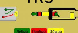
How does a headphone plug work?
If the cable is frayed, torn or the plug (pin) comes off, the device is repaired using a soldering iron with consumables and a new connector (if that is the problem).
Headphones 3.5mm
Since the 3.5 mm connectors are non-separable, for repairs you will have to buy a dismountable one, crimp the cable with a special clamp, solder the contacts according to the diagram shown below and assemble the connector.
3.5 mm plug structure
Manufacturers adhere to standards in insulation painting:
- red – left speaker – first contact or tip;
- green – right channel or ring;
- blue – speaker;
- colorless or copper-colored - mass;
- a different color – leads to the control panel (buttons).
In more expensive models, each channel may have its own mass: red-copper is the mass for the left channel, and green-copper is for the right. The microphone cable is sometimes shielded with a braided cable and varnished.
The coloring of the insulation is often violated, so relying on the coloring is wrong. To determine which pin corresponds to which channel, put on headphones and ring all combinations of wires one by one until the speaker starts to make noise. This way you can determine the mass and both channels.
The resistance between the headphones is twice as high as between ground and the audio channel.
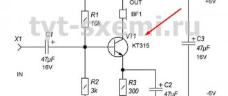
Headphone circuit with microphone
For a headset, the schematic drawing looks different, because it is designed differently - equipped with an additional cable for transmitting sound from a microphone.
Have you noticed that in the diagrams there are different contacts for ground and microphone? Nothing strange. There are a couple of TRRS types (specifications) available with different ground and microphone contact locations. In CTIA (computer standard), the second ring (third contact) is connected to the common contact, and the sleeve is connected to the microphone, in the case of OMTP (telephone specification) it is the other way around: the 3rd contact is the speaker, the 4th is ground.
The standards are relevant only for headsets - headphones with a microphone; they have no relation to devices without one.
The standards are relevant only for headsets - headphones with a microphone; they have no relation to devices without one.
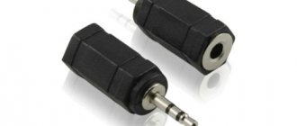
Figure No. 1
We noticed that some headsets with iPhone work adequately. The microphone fails, the volume control and track switching do not function due to the fact that most accessories are produced with the international OMPT pinout, and Apple uses the American circuit - CTIA. The problem is solved by purchasing a CTIA - OMPT adapter (see Figure No. 1) or by resoldering the 3rd and 4th contacts (they are swapped) in the headset.
The headphone pinout will allow you to correctly solder the pins when repairing the device, for example, replacing a damaged plug or cable. It depends on the number of contacts and the specification used: CTIA or OMPT.
Adapter 9 to 15 contacts
| Purpose of the 9-pin connector pin | № | № | Purpose of the 15-pin connector pin |
| Red | 1 | 1 | Red |
| Green | 2 | 2 | Green |
| Blue | 3 | 3 | Blue |
| Horizontal Sync | 4 | 13 | Horizontal Sync |
| Vertical Sync | 5 | 14 | Vertical Sync |
| Red (body) | 6 | 6 | Control red |
| Green (body) | 7 | 7 | Control green |
| Blue (body) | 8 | 8 | Control blue |
| Sync signal (housing) | 9 | 10 | Housing (digital) |
| 5 | Frame |
Foreign pinout of wires by color
The main colors for marking abroad are as follows:
- neutral - white, gray or black;
- protective grounding - yellow or green.
- Standards in a number of countries allow the use of bare metal without insulation as protective grounding.
Grounding wires are switched on prefabricated non-insulated terminals and connect to each other all metal parts of the structure that do not have reliable electrical contact with each other. When assembling the electrical panel
Game port pin assignments
| № | Signal |
| 1 | +5V |
| 2 | Button 4 |
| 3 | Position 0 |
| 4 | Frame |
| 5 | Frame |
| 6 | Position 1 |
| 7 | Button 5 |
| 8 | +5V |
| 9 | +5V |
| 10 | Button 6 |
| 11 | Position 2 |
| 12 | Frame |
| 13 | Position 3 |
| 14 | Button 7 |
| 15 | +5V |
Classification of wires by letter designation
The pinout of wires can be not only by color, but also by letter. Partially the symbols for the designation are standardized:
L (from the word Line) - phase wire; N (from the word Neutral) - neutral wire; PE (from the combination Protective Earthing) - grounding; “+” - positive pole; “-” - negative pole; M is the midpoint in DC circuits with bipolar power supply. The terminals for connecting the protective grounding are indicated by a special symbol, which is stamped on the terminal or on the body of the device in the form of a sticker. The grounding symbol is the same for most countries of the world, you will agree that it is convenient and safe.
Replacing electricity meters: at whose expense is the electricity meter changed and in what case
Multiphase networks
In multiphase networks, the symbols are supplemented by the serial number of the phase:
L1 - first phase; L2 - second phase; L3 - third phase. There is marking according to old standards, when the phases are designated by the symbols A, B and C.
Combined phase designation system
A deviation from the standards is the combined phase designation system:
La - first phase; Lb - second phase; Lc - third phase.
Phase designation
Soviet era phase designation
In the vast expanses of the post-Soviet space, you can still find the designation of the phases of Soviet times, where the letters are depicted in the Latin alphabet A, B, and C. A departure from generally accepted international standards is also observed in the combined letter marking: LA, LB, LC.
How to correctly report data for electricity: how to transmit, when and in what way
Motherboard expansion slots
(not really about cables, but useful)
8 bit slot
| Installation side | Solder side | ||||
| № | Signal | Meaning | № | Signal | Meaning |
| A1 | I/O CH CK | I/O channel monitoring | B1 | GND | Earth |
| A2 | D7 | Data line 8 | B2 | RES DRV | Reset signal |
| A3 | D6 | Data line 7 | B3 | +5V | +5V |
| A4 | D5 | Data line 6 | B4 | IRQ2 | Interrupt request 2 |
| A5 | D4 | Data line 5 | B5 | -5V | -5V |
| A6 | D3 | Data line 4 | B6 | DRQ2 | DMA request 2 |
| A7 | D2 | Data line 3 | B7 | -12V | -12V |
| A8 | D1 | Data line 2 | B8 | RES | Reserved |
| A9 | D0 | Data line 1 | B9 | +12V | +12V |
| A10 | I/O CN RDY | I/O channel readiness monitoring | B10 | GND | Earth |
| A11 | AEN | Address Enable, bus control with CPU and DMA controller | B11 | MEMW | Data is written to memory |
| A12 | A19 | Address line 20 | B12 | MEMR | Data is read from memory |
| A13 | A18 | Address line 19 | B13 | IOW | Data is written to the I/O port |
| A14 | A17 | Address line 18 | B14 | IOR | Data is read from the I/O port |
| A15 | A16 | Address line 17 | B15 | DACK3 | DMA-Acknowledge 3 |
| A16 | A15 | Address line 16 | B16 | DRQ3 | DMA 3 request |
| A17 | A14 | Address line 15 | B17 | DACK1 | DMA-Acknowledge 1 |
| A18 | A13 | Address line 14 | B18 | IRQ1 | Interrupt request 1 |
| A19 | A12 | Address line 13 | B19 | REFRESH | Memory regeneration |
| A20 | A11 | Address line 12 | B20 | CLC | System clock 4.77 MHz |
| A21 | A10 | Address line 11 | B21 | IRQ7 | Interrupt request 7 |
| A22 | A9 | Address line 10 | B22 | IRQ6 | Interrupt request 6 |
| A23 | A8 | Address line 9 | B23 | IRQ5 | Interrupt Request 5 |
| A24 | A7 | Address line 8 | B24 | IRQ4 | Interrupt request 4 |
| A25 | A6 | Address line 7 | B25 | IRQ3 | Interrupt request 3 |
| A26 | A5 | Address Line 6 | B26 | DACK2 | DMA-Acknowledge 2 |
| A27 | A4 | Address line 5 | B27 | T/C | Terminal Count, signals the end of DMA transformation |
| A28 | A3 | Address line 4 | B28 | ALE | Adress Latch Enabled, address/data uncoupling |
| A29 | A2 | Address line 3 | B29 | +5V | +5V |
| A30 | A1 | Address line 2 | B30 | O.S.C. | Clock frequency 14.31818 MHz |
| A31 | A0 | Address line 1 | B31 | GND | Earth |
16 bit slot
| Installation side | Solder side | ||||
| № | Signal | Meaning | № | Signal | Meaning |
| A1 | I/O CH CK | I/O channel monitoring | B1 | GND | Earth |
| A2 | D7 | Data line 8 | B2 | RES DRV | Reset signal |
| A3 | D6 | Data line 7 | B3 | +5V | +5V |
| A4 | D5 | Data line 6 | B4 | IRQ9 | Cascading the second interrupt controller |
| A5 | D4 | Data line 5 | B5 | -5V | -5V |
| A6 | D3 | Data line 4 | B6 | DRQ2 | DMA request 2 |
| A7 | D2 | Data line 3 | B7 | -12V | -12V |
| A8 | D1 | Data line 2 | B8 | RES | Memory communication without latency |
| A9 | D0 | Data line 1 | B9 | +12V | +12V |
| A10 | I/O CN RDY | I/O channel readiness monitoring | B10 | GND | Earth |
| A11 | AEN | Address Enable, bus control with CPU and DMA controller | B11 | SMEMW | Data is written to memory (up to 1M byte) |
| A12 | A19 | Address line 20 | B12 | SMEMR | Data is read from memory (up to 1 MB) |
| A13 | A18 | Address line 19 | B13 | IOW | Data is written to the I/O port |
| A14 | A17 | Address line 18 | B14 | IOR | Data is read from the I/O port |
| A15 | A16 | Address line 17 | B15 | DACK3 | DMA-Acknowledge 3 |
| A16 | A15 | Address line 16 | B16 | DR Q3 | DMA 3 request |
| A17 | A14 | Address line 15 | B17 | DACK1 | DMA-Acknowledge 1 |
| A18 | A13 | Address line 14 | B18 | IRQ1 | Request IRQ 1 |
| A19 | A12 | Address line 13 | B19 | REFRESH | Memory regeneration |
| A20 | A11 | Address line 12 | B20 | CLC | System clock 4.77 MHz |
| A21 | A10 | Address line 11 | B21 | IRQ7 | IRQ 7 request |
| A22 | A9 | Address line 10 | B22 | IRQ6 | IRQ 6 request |
| A23 | A8 | Address line 9 | B23 | IRQ5 | Request IRQ 5 |
| A24 | A7 | Address line 8 | B24 | IRQ4 | IRQ 4 request |
| A25 | A6 | Address line 7 | B25 | IRQ3 | IRQ 3 request |
| A26 | A5 | Address Line 6 | B26 | DACK2 | DMA-Acknowledge 2 |
| A27 | A4 | Address line 5 | B27 | T/C | Terminal Count, signals the end of DMA transformation |
| A28 | A3 | Address line 4 | B28 | ALE | Adress Latch Enabled, address/data uncoupling |
| A29 | A2 | Address line 3 | B29 | +5V | +5V |
| A30 | A1 | Address line 2 | B30 | O.S.C. | Oscillator clock 14.31818 MHz |
| A31 | A0 | Address line 1 | B31 | GND | Earth |
| C1 | SBHE | System Bus High Enabled, 16-bit data signal | D1 | MEMCS 16 | Memory Chip Select |
| C2 | LA23 | Address line 24 | D2 | I/O CS 16 | I/O card with 8 bit/16 bit carryover |
| C3 | LA22 | Address line 23 | D3 | IRQ10 | Interrupt request 10 |
| C4 | LA21 | Address line 22 | D4 | IRQ11 | Interrupt request 11 |
| C5 | LA20 | Address line 21 | D5 | IRQ12 | Interrupt request 12 |
| C6 | LA19 | Address line 20 | D6 | IRQ15 | Interrupt request 15 |
| C7 | LA18 | Address line 19 | D7 | IRQ14 | Interrupt request 14 |
| C8 | LA17 | Address line 18 | D8 | DACK0 | DMA-Acknowledge 0 |
| C9 | MEMR | Reading data from memory | D9 | DRQ0 | DMA request 0 |
| C10 | MEMW | Writing data to memory | D10 | DACK5 | DMA-Acknowledge 5 |
| C11 | SD8 | Data line 9 | D11 | DRQ5 | DMA 5 request |
| C12 | SD9 | Data line 10 | D12 | DACK6 | DMA-Acknowledge 6 |
| C13 | SD10 | Data line 11 | D13 | DRQ6 | DMA 6 request |
| C14 | SD11 | Data line 12 | D14 | DACK7 | DMA-Acknowledge 7 |
| C15 | SD12 | Data line 13 | D15 | DRQ7 | DMA 7 request |
| C16 | SD13 | Data line 14 | D16 | +5V | +5V |
| C17 | SD14 | Data line 15 | D17 | MASTER | Busmaster signal |
| C18 | SD15 | Data line 16 | D18 | GND | Earth |
Other pins
- 3.3V pin can be used to power low-power sensors and modules: the maximum current that can be removed from the 3.3V pin is 150 mA, which is enough for any sensors and modules, except perhaps the nrf25L01 radio modules.
- GND pins – power ground, all GNDs are interconnected
- Pin 5V – power supply from a source with a voltage of up to 5.5V (for more details about power supply, see the next lesson)
- Pin Vin – power from a source with a voltage of 7-15V (for more details about power supply, see the next lesson)
- RST – MK reboot. This pin is also displayed on the button
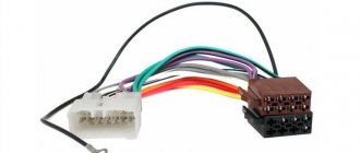
Markings and types of connectors
To answer your silent question about what kind of connectors there are in car radios, I must answer that most modern car radios are equipped with two standard connectors, designated by the abbreviation “ISO”. Each of these connectors is designed as an eight-pin rectangular plug, sometimes they are combined into one housing (see photo).
Car radio ISO connector pinout
One of the connectors carries “power” circuits, that is, current consumption sources are connected to it, and is designated in the diagrams as a connector under the letter “A” and is colored brown. The second connector is intended for connecting the car’s acoustic system, in other words, speakers. Unlike the previous one, it is made in black and is designated on electrical circuit diagrams as connector “B”.
What connectors do car radios have?
Sometimes there are car radios with three connectors, but this is the exception rather than the rule. The same exception as non-standard connectors, which still have wiring with standard markings and in any case allow you to connect the wires of a standard speaker system with non-standard “connections” in at least two ways. So:
- “Skolkhoz”, namely, cut off the non-standard plug and overlap the wires, which “is not very good”, since over time the twist will become loose due to oxidation/shaking and, in the best case, you will have to do all the work again while simultaneously replacing the fuses.
Pinout of ISO connectors for car radios
- Buy an adapter (the price of which is in no way close to the amount of work that the method described above includes) and, without any problems, decorously/nobly, connect the car radio with other elements of the acoustic circuit of your car.
The choice of adapters at the moment is huge, and it is simply physically impossible for any troubles to arise in the use of this variety.
Car radio ISO connector pinout