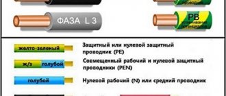
A type of electrical connector used primarily in professional audio and lighting applications.
XLR3 cable connectors, female left and male right
XLR connector
is a type of electrical connector mainly found on professional audio, video and stage lighting equipment. The connectors are circular in shape and have three to seven pins. They are most often associated with balanced audio interconnects, including AES3 digital audio, but are also used for lighting control, low-voltage power supplies, and other applications. XLR connectors are available from a number of manufacturers and comply with the international sizing standard IEC 61076-2-103. [1]
The XLR connector is similar in appearance to the smaller DIN connector, but is not physically compatible. A smaller version, the mini XLR connector, is sometimes used on small equipment.
Content
- 1 History and manufacturers
- 2 Design
- 3 Current patterns and applications 3.1 Three-pin (XLR3)
- 3.2 Four-pin (XLR4)
- 3.3 Five-pin (XLR5)
- 3.4 Six-pin (XLR6)
- 3.5 Seven-pin (XLR7)
- 3.6 PDN
- 4.1 Two-pin (XLR2)
- 5.1 Three-pin when using audio
History and manufacturers [edit]
A variety of male and female XLR connectors with different numbers of pins
The XLR connector was invented by James H. Cannon, founder of Cannon Electric in Los Angeles, California (now part of ITT Corporation), and for this reason it was sometimes colloquially called a
Cannon
plug or
Cannon connector
.
Originally released as the Cannon X
Cannon XL
was added by 1950 [2] and by 1955[2] a version surrounding female contacts with synthetic rubber insulated polychloroprene (neoprene) using the part number prefix
XLR
.
[3] [4] There was also an XLP
which used hard plastic insulation but was otherwise the same. [2] ITT Cannon originally manufactured XLR connectors in two locations: Kanagawa, Japan and Melbourne, Australia. The Australian subsidiary was sold to Alcatel Components in 1992 and then acquired by Amphenol in 1998. ITT Cannon continues to manufacture XLR connectors in Japan.
Switchcraft Corporation later began producing compatible connectors, followed by Neutrik. Neutrik made a number of improvements to the connector, and its second generation design (known as the X Series) had only four parts for the cable connector and eliminated the small screws used by both Cannon and Switchcraft that were prone to loosening, falling out, and getting lost.
How to connect the XLR connector
An XLR connector is a type of electrical connector used primarily on professional audio, video and lighting equipment. The connectors are circular in design and have 3 to 7 pins. They are most often associated with balanced audio connections, including AES3 digital audio, but are also used to control lighting, low-voltage power supplies, and other devices. XLR connectors are available from a number of manufacturers and comply with the international sizing standard, IEC 61076-2-103. They are similar in appearance to older and smaller DIN connectors, but are not physically compatible with them. A smaller version, the Mini XLR Connector, is used on miniature and portable equipment.
A simple connector for connecting a loudspeaker.
History and manufacturers
The XLR connector was invented by James H. Cannon, founder of Cannon Electric in Los Angeles, California (now part of the ITT Corporation), and for this reason it was sometimes known as the Cannon plug or Cannon. Originally manufactured as the Cannon X series, a locking mechanism (Cannon XL) was added by 1950, and by 1955 a version isolating contacts in female connectors, with polychloroprene synthetic rubber insulation using the XLR part number prefix. There was also the XLP series which used hard plastic insulation but was otherwise the same. ITT Cannon initially manufactured XLR connectors in two locations: Kanagawa, Japan and Melbourne, Australia. The Australian company was sold to Alcatel Components in 1992 and then acquired by Amphenol in 1998. ITT Cannon continues to produce XLR connectors in Japan.
A variety of XLR connectors with different numbers of pins.
Later, Switchcraft Corporation began producing compatible connectors. Neutrik made a number of improvements to the connector, and its second generation design (known as the X-Series) had only four parts for the cable connector and did away with the small screws used by both Cannon and Switchcraft, which were prone to falling out and getting lost in heavy use.
Design
XLR connectors come in male and female styles, both for cable and housing installation, for a total of four styles.
XLR connectors are designed to connect the first pin 1 (ground pin) before the other pins are connected when an XLR connector is inserted. With a ground connection established before connecting the signal lines, insertion (and removal) of XLR connectors into audio equipment is possible without distorting external signals (as typically happens with RCA connectors, for example).
XLR-LNE with three pin connectors and connectors originally used for network connection. Please note that the panel connector is covered for safety reasons.
The number of contacts fluctuates. Since 2016, XLR connectors are available in 2-pin and up to 10-pin, and mini-XLR connectors up to eight. XLR connectors from different manufacturers are compatible, with the exception of six-pin Switchcraft models, which use a non-standard pin layout.
From left to right: Cannon XLR3-12C (Line), X3F Switch (Line), Neutrik NC3MP Panel, Neutrik NC3FP Panel
Current Connector Patterns
Three-pin (XLR3)
Three-pin XLR connectors are the most common and are the industry standard for balanced audio signals. The vast majority of professional microphones use an XLR connector. In previous years they were used to connect loudspeakers such as Trace Elliot in bass cabinets. XLR can use 14 AWG (1.6 mm) wire with a current carrying capacity of 15 A, suitable for most speakers, but they are replaced by the Speakon connector for professional speakers. The Speakon connector accepts larger wire gauges and higher current carrying capacity, and it provides better protection against insulation flashovers, which can carry dangerous voltages when connected to an amplifier. Three-pin XLR connectors are used to connect line-level speakers.
There are devices with battery charging capabilities that use three-pin XLR connectors. They can be found on electric power wheelchairs and scooters. The connectors transmit 2 to 10 amps at 24 volts.
XLR and 0.25" TRS telephone combo jack.
The legacy use of three-pin XLR connectors was reserved for MIDI keyboards and some Octave-Plateau synthesizers, including the Voyetra-8.
The three-pin XLR connector is commonly used for DMX512, for lighting and related control equipment. However, the use of three-pin XLR connectors for DMX512 is specifically prohibited in section 7.1.2 of the DMX512 standard. Using a three-pin XLR in this context firstly poses the risk of damage to lighting equipment if a 48 volt phantom power audio cable is accidentally connected, and secondly encourages the use of a cable to DMX analogue audio specifications, which could lead to signal degradation and unreliable DMX network operation.
1. Ground (Shield) 2. Positive polarity terminal for balanced audio circuits (“hot”) 3. Negative polarity terminal for balanced circuits (otherwise known as “cold”)
Four-pin (XLR4)
Four-pin XLR connectors are used in a variety of devices. These connectors are standard on telephone headsets such as the ClearCom and Telex systems. Two pins are used for the mono headphone signal and two more pins for the unbalanced microphone signal. Another common application is DC power supply for professional film and video cameras and related equipment. Some desktop microphones with LEDs use them. The fourth pin is used to power an LED indicating that the microphone is on. Other uses for the four-pin XLR include some scrollers (color changing devices for stage lighting), AMX analog control (now obsolete), and some pyrotechnic equipment.
Five-pin (XLR5)
Five-pin XLR connectors are standard for DMX512 digital lighting control. Other common applications are two-element or stereo microphones (two balanced audio signals with a common ground) and stereo headset (3 pins for the stereo headphone signal - left, right and ground and 2 pins for the unbalanced microphone signal). Additionally, 5-pin XLR is commonly used for DC power in audio equipment.
Female and pin connectors for housings.
Female connector.
Pin connector.
Six-pin (XLR6)
Six-pin XLR connectors are used for two-channel intercom systems and stage lighting controls. Another common application is a professional stereo headset with a balanced microphone (left headphone pin 4, right headphone pin 5, headphone common pin 3, mic pin 1, low pin mic 2, mic ground pin 6).
7-pin (XLR7)
Seven-pin XLR connectors are used to connect some (tube) condenser microphones to their power supplies (carrier signal, polarization voltage, heater, etc.). Used by several models of Le Maitre and Ultratec smoke machines for remote control. The legacy use for seven-pin XLR connectors was as an analog lighting control signal as well as wired intercom in broadcast studios, particularly with Ward-Beck intercoms.
PDN
The Cannon loudspeaker (known as a PDN connector) had blue or white insulation (depending on its gender), designed for connections between audio power amplifiers and loudspeakers. They are manufactured by Amphenol (formerly Alcatel Components and ITT Cannon Australia).
Technical information about use
Using three-pin audio connectors
The EIA RS-297-A standard describes the use of a three-pin XLR—known as XLR3—for devices that support balanced audio levels:
Before the introduction of this standard, pinout pinouts, pins 2 and 3 changed among themselves. Pin 2 "hot" and pin 3 "cold" was commonly used by European and Japanese equipment manufacturers, but American companies used pin 3 as "hot" and 2 as "cold". This caused problems when connecting equipment with unbalanced wiring diagrams. Pin 3 "hot" as standard, now obsolete but still used on vintage equipment. Pin 1 is always grounded and/or shielded if the cable itself is shielded, and many connectors connect it internally to the chassis body or connector body.
Although there is still some disagreement in industry technical standards regarding the best way to use Pin 1 for grounding. The main debate is whether the metal shell of the connector should be connected to pin 1 or the shield, or left floating. The AES standards mentioned above recommend that interconnect cable sheaths should never be connected to pin 1 or the shield, since inadvertent contact of the sheath with another grounded surface during use can create unwanted current loads, potentially causing noise and other distortion. On the other hand, equipment containing active circuits should always have pin 1 connected to the conductive body of the equipment, as close as possible to the point where the signal enters the body. An argument for this may be the RF shielding provided by the connector shell, which can be weakened if this pin is not connected to anything. An alternative solution is to connect the sheath to pin 1 and the shield via a small capacitor that provides RF shielding but allows very little audio current to flow. This capability can be built into an XLR jack or cable.
Because equipment often requires a TRS or XLR input, Neutrik and Amphenol offer several combo jack models that support both XLR and 0.25-inch TS or TRS telephone jacks.
Use as a four-pin DC power supply
The most common use for this connector is that pin 1 should be grounded and pin 4 should be 12 volts (nominal), with pins 2 and 3 not being used. This configuration is used on most professional camcorders and is also common on portable audio equipment. There are other non-standard uses for this connector, especially on older devices.
Use as a four-pin headset
Clear-Com, Telex, RTS and many other industrial intercom systems use four-pin XLR connectors to connect mono headsets or telephones. Standard pinout for four-pin XLR headsets: Pin 1 = Mic Ground (shield/shield); Pin 2 = microphone input ("hot"); Pin 3 = Headphone Ground (Return); Pin 4 = Headphone output ("hot").
Five-pin - DMX512 and DC Power for audio systems
The 5-pin XLR is the standard connector for DMX512, the most common protocol for controlling professional lighting and related equipment. Three-pin XLR connectors are becoming more common. They are electrically compatible with a simple 1-1, 2-2, 3-3 jumper between them. However, the use of three-pin XLR connectors for DMX512 is specifically prohibited in section 7.1.2 of the DMX512 standard.
The five-pin XLR is also a common power connector in modular professional audio systems such as Automated Processes, Inc.'s Lunchbox format. (API). This format is becoming increasingly popular, and 5-pin XLR for DC power is used by many third-party modules and chassis designers such as BAE Audio and JLM Audio. It is also used by Slate Digital for the VMS1 mic preamp. Typical contact configuration:
Pin 1: Chassis Ground
Pin 2: Power
Pin 3: Positive voltage (typically +15V or +16V)
Pin 4: Negative voltage (usually 15V or -16V)
Pin 5: Phantom Supply Voltage (typically +48 volts)
Typically, audio signals on XLR connectors "follow the pin" so that the external connector is the output and the female connector is the input. In most device power applications (not just XLR connectors), the female connector is the output and the male connector is the input. This makes accidental contact with live parts less likely. In audio devices, this also prevents the accidental use of DC power to input signals.
Additional usage information
At one time, three-pin XLR connectors were also widely used on speaker cables, as when first introduced they represented a new standard in strength and cost-effective alternatives were not available. Often a two-wire speaker would have three-pin female connectors on both ends to distinguish it from a three-wire shielded cable, which has one connector on one end and a male connector on the other.
Phantom power
Some microphones, such as condenser microphones, require power. An alternative to battery power is phantom power, which consists of direct current applied equally through two signal lines of a balanced audio connector, typically a three-pin XLR connector. The supply voltage is found at the ground pin of the connector (XLR pin 1), which is usually connected to the cable shield or the ground wire in the cable, or both. Phantom power is typically supplied at a nominal DC voltage of 48 volts, although lower voltages are acceptable and modern microphones often operate over a wide range.
Modern mixers often feature a built-in 48-volt, mains-powered power supply that supplies all microphone inputs with phantom power, thereby eliminating the need for bulky external power supplies for individual microphones.
XLD key
The XLD connector is a proposed variant with XLR connectors. Keys prevent accidental mixing of XLR and XLD connectors. XLD connectors and connectors are used primarily in professional cables for audio and video electronics.
The XLD connector is offered by the Audio Engineering Society's AES42 digital microphone interface standard.
The connectors are similar to XLR, but with an additional coding key and groove that allows you to control the switching between XLD and XLR connectors. A connector with an encoding key installed will not mate with a connector that does not have a corresponding groove. Thanks to the appropriate connectors, analog microphones can be protected from damage by a high-precision digital phantom power supply for digital microphones.
XLR and Mini XLR connectors
Mini XLR Connector
XLR and Mini XLR connectors
The Mini XLR connector, also known as the "TQG" or "TA3"/"TA4" connector (numbered depending on the number of poles), is used on compact devices such as UHF wireless protein microphones, some studio and field recording headphones, and also Audio Technica condenser microphones, but not used primarily for basic items such as mixing consoles. The Mini XLR Connector was first developed by Switchcraft, and is also available from Rean, and various other sources. So far, Mini XLR connectors do not appear to be supported by any ISO or national standards.
Design[edit]
XLR connectors are available in male and female versions, both cable and chassis mounted, for a total of four styles. This is a bit unusual as many other connector designs are missing one of the styles (usually a chassis mount male).
XLR female connectors are designed to connect pin 1 (ground pin) first before the other pins make contact when an XLR male connector is inserted. With grounding established before signal lines are connected, insertion (and removal) of XLR connectors into live equipment is possible without receiving external signals (as is typically the case with RCA connectors, for example).
The number of contacts varies. As of 2016, XLR connectors are available in up to 10 pins [5], and mini XLR connectors are available in up to eight pins. XLR connectors from different manufacturers will interact with each other, with the exception of six-pin models, which are available in two incompatible designs. The older six-pin Switchcraft design adds a center pin to the standard five-pin design, while the newer Neutrik design uses a different pattern. The Switchcraft six-pin will accept a standard five-pin connector, whereas the Neutrik design will not have a six-pin connector. Neutrik currently offers both connectors with six pins.
The terminology for designating the corresponding elements of a pair of mating connectors follows the usual rules for gender connectors: a "male" connector is a connector with pins on the smallest
The “encompassing” element has corresponding sockets.
A "male" connector fits into a "female" connector, as judged by the largest element. For most XLRs, the plugs are male and the females are female. XLRs are unusual because, at least in audio applications, all four combinations of plugs and sockets, plugs and sockets, are equally common.
A common misconception is that "plugs" are free sockets [ii] and "receptacles" are panel mounted, but XLR uses a lot of free female sockets and panel plugs. There is a loose convention for audio work in which signals are generated by equipment with pins and transmitted to those with sockets. The XLR connector has a circumference of 59.7 mm (2.35 inches) at its widest point. [citation needed ]
Switching Tips
Now I want to give you a number of tips on switching in a home recording studio. You should remember and follow them as much as possible. These are the recommendations:
- Use only high quality cables and connectors
.
Don't skimp on this. Of course, buying a cable that costs several tens of dollars per meter for less budget equipment will be pointless. But buying fake and low-quality products for a couple of rubles per meter from unknown manufacturers is also not an option. I trust manufacturers such as Klotz
and
Proel
. - Use the same cables to connect the same components.
For example, when connecting monitors to an audio interface, each of them must be connected to the interface with the same cable. Moreover, both in length and wiring, and in terms of the manufacturer’s company and even the model itself. - Choose a balanced connection.
This connection produces much less noise that occurs from various interferences and allows the use of longer cables. - Prefer connections using XLR connectors whenever possible.
They have better characteristics compared to others. But if you don’t have this option, for example, when the outputs of the audio interface are jack, and the input is jack and xlr, then use a jack to jack cable. - If you decide to solder the cables yourself, be very careful not to mix up the signal wires.
Otherwise, such a thing as antiphase may occur, and when recording a stereo signal, in this case, no sound will be heard at all. And during playback, the sound will be mutually suppressed, that is, one channel will eat up the other. Therefore, if you decide to solder the cable yourself, then follow the diagrams included in this article.
This concludes our discussion of the topic. Now you know what the wiring should be like in a home recording studio. You already know what type of cable is best to use, what types of connectors there are and cable wiring diagrams. Also at the end I gave you some useful tips for connecting cables in the studio. Try to be sure to follow them.
(435 ratings, average: 5.00 out of 5)
Before moving on to the question of what an XLR connector is , we need to touch on the understanding of the causes of interference and the classification of audio signal transmission. Since the advent of electricity, a person’s daily life, his daily life and entertainment has changed dramatically. Devices have appeared without which modern man can no longer live a day. These are all kinds of lighting devices, electric motors involved in production and in everyday life, their use entails an increase in living standards. It seems impossible to remain without them now, however, electricity as a form of energy is considered a pollutant and a source of interference for any audio signal transmitted over a distance. Household appliances, the Internet, stabilizers, refrigerators, mixers, rectifiers, etc. cause extraneous noise in the audio channel. Thus, there is a need for protection from external negative influences transmitted through cords and connectors, sound signals of different frequencies and amplitudes.
Current templates and applications[edit]
Three-pin (XLR3) [edit]
Three-pin XLR connectors are by far the most common style and are the industry standard for balanced audio signals. The vast majority of professional microphones use an XLR connector. In previous years they were used to connect loudspeakers such as Trace Elliot in their bass enclosures. [6] XLR can handle 14 AWG (1.6 mm or 0.063 in) wire with a current carrying capacity of 15 amps, which is suitable for most speakers, but they have been replaced by the Speakon connector for professional speakers. The Speakon connector can accept larger wires and carry more current, and provides better shielding for contacts that may carry dangerous voltages when connected to an amplifier. [7]
Three-pin XLR connectors are used to connect powered speakers with line level signals. This use is commonly seen in PA system applications and appears to be becoming more common. [ original research?
]
There are rechargeable devices that use three-pin XLR connectors. They can be found on electric wheelchairs and scooters. The connectors can handle 2 to 10 amps at 24 volts. [ citation needed
]
Deprecated use of three-pin XLR connectors for MIDI data on some Octave-Plateau synthesizers, including the Voyetra-8.
The three-pin XLR connector is commonly used for DMX512, on lighting and related control equipment [8], especially in the budget/DJ market. However, the use of three-pin XLR connectors for DMX512 is specifically prohibited by section 7.1.2 of the DMX512 standard. [9] Using a three-pin XLR in this context firstly poses a risk of damage to lighting equipment if an audio cable with 48-volt phantom power is accidentally connected, and secondly encourages the use of the cable according to analogue audio specifications for DMX. , which can lead to poor signal quality and unreliable DMX network operation. [ citation needed
]
Four-pin (XLR4)[edit]
Four-pin XLR connectors are used in a variety of applications. [10]
They are standard connectors for intercom headsets such as ClearCom and Telex systems. Two pins are used for the monophonic headphone signal and two pins for the unbalanced microphone signal. [ citation needed
]
Another common use is to provide DC power for professional film and video cameras and related equipment. Some desktop microphones with LEDs use them. The fourth pin is used to power an LED indicating that the microphone is on.[11] Other uses of the four-pin XLR include some scrollers (color changing devices for stage lighting), AMX analog lighting controls (now obsolete), and some pyrotechnic equipment. [ citation needed
]
The 4-pin XLR connector is used for balanced headphone connections from a balanced amplifier where there is no common ground between the two channels. Connection diagram: 1 - left channel + phase; 2 - left channel - phase; 3 - right channel + phase; 4 - right channel - phase. [12]
Five-pin (XLR5)[edit]
Five-pin XLR connectors are the standard for DMX512 digital lighting control. [13]
Other common uses are two-element or stereo microphones (two balanced audio signals with a common ground) and stereo intercom headset (three pins for the stereo headphone signal - left, right and ground, and two pins for the unbalanced microphone signal). . [ citation needed
]
Additionally, five-pin XLR is commonly used for DC power in audio equipment. [ citation needed
]
Six-pin (XLR6) [edit]
Six-pin XLR connectors are used for two-channel intercom systems [14] and stage lighting control applications. [15][16][17] Another common application is a professional stereo headset with a balanced microphone (left headphone jack 4, right headphone jack 5, general headphone jack 3, top mic pin 2, bottom mic pin 1, ground pin microphone 6). [ citation needed
]
Seven-pin (XLR7) [edit]
Seven-pin XLR connectors are used to connect some tube condenser microphones to power supplies (transmit signal, polarization voltage, heater and HT). [18]
Several models of Le Maitre and Ultratec fog machines are used for remote control. [ citation needed
]
An outdated use of seven-pin XLR connectors was for analog lighting control signals, as well as for wired intercoms in broadcast studios, especially with Ward-Beck intercoms. [ citation needed
]
PDN [edit]
Loudspeaker Cannon
(known as
PDN
connector) had blue or white insulation (depending on its gender), and was intended for connection between audio power amplifiers and loudspeakers.
They are manufactured by Amphenol (formerly Alcatel Components and ITT Cannon Australia). [ citation needed
]
What to look for when purchasing
The mandatory seven criteria that must be taken into account when purchasing cables with XLR connectors are:
- The use of a cable, as well as the ability to operate it in an environment with a lot of interference, determines the degree of its protection from them and, as a consequence, its cost.
- In an environment with high interference levels, especially wireless communications, it is necessary to use the maximum level of protection with spiral double braiding and conductive PVC for signal purity.
- If operation may require frequent bending, then it is better to use a spiral screen rather than a wicker one.
- The shielding and connection of this protective layer to grounding must be done as reliably as possible.
- Correct switching and wiring, as well as shielding along the entire length of the cable, are the key to reliable protection against interference.
- Gold-plated or silver-plated contacts should not have mechanical damage or scratches.
- The material from which the XLR connector affects only the contact resistance in the contact part, but does not protect against external interference and noise generated by the cable itself.
It must be remembered that a poorly soldered connector and damaged insulation, as well as the cable shield, will affect the frequency quality of the transmitted signal, especially as its length increases. Also remember that as the length of the connecting cable increases, there is a problem with frequency response attenuation, but this often only applies to extremely long distances between the microphone and the preamplifier.
Outdated templates[edit]
Three-pin XLR-LNE male and female connectors, originally used for network connections. The connecting pins in the male connector are recessed and the sockets in the female connectors are covered for safety. This example is a panel socket used as a plug power input, although they have also been used in the opposite configuration.
| In this section do not cite any sources . |
There are many other types of connectors using the XLR type jacket, with different pin configurations. One of them is the now obsolete three-pin power circuit connector manufactured by ITT Cannon.
Power gun
(also called
XLR-LNE
connector) was covered with pins and red insulation; it was intended as a mains power plug, an alternative to the IEC 60320 series connectors, but was only used on a few pieces of equipment.
Two-pin (XLR2) [edit]
A two-pin variant was used as the DC input jack on the 1970s Yamaha CP series 'Electric Grand' pianos (CP-60, CP-70 and CP-80).
Types of connectors
Let's look at the types of connectors we need. However, first, you need to understand the components:
- The jack
is where the cable is connected; - The plug
is what is connected.
There are 4 types of connectors used in recording studios:
Jack
(can be called thick or large jack)
- its size is 6.3 mm.
It is also designated as 1.4 inches. The jack plug can be two-pin or three-pin. Two-pin (TS)
comes from
(Tip) (3)
, that is, the tip and
(Sleeve) (1)
, that is, the sleeve itself.
All this is separated by a plastic black ring (4)
.
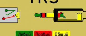
Essentially there are two contacts - type and sleeve. As for the three-pin jack (TRS)
, there is a Tip
(3)
, a Sleeve
(1)
and an additional Ring
(ring in the plug) (2)
, which is connected to a pro-channel contact or an inverted phase of the signal.
Three-pin jacks are used not only as stereo, but also as balanced mono cables with certain wiring. That is, if a three-pin jack can be used in mono and stereo, then a two-pin jack can only be used as a mono jack. The jack connector is usually used when connecting a guitar, keyboard instruments (for example, a synthesizer)
, microphones, and sound effects processors. This stereo jack connector can also be used for balanced connection of monitors to a sound card and connection to it of a microphone preamplifier and headphone amplifier. In fact, this is a fairly universal connector.
Mini jack
— this connector, except for its size, is no different. There are both two-pin and three-pin. In a professional environment, minijack is probably only used in headphones. Therefore, we will not dwell on it in more detail.
Canon XLR
(XLR 3)
is a professional connector and, as a rule, is not used in household audio equipment.
It is a metal (sometimes plastic)
connector with three pins. As with the jack, these pins correspond to three contacts: sleeve, tip and ring. Using this xlr connector, a fairly large amount of studio equipment is switched. For example, monitors, an audio interface, a preamp with a microphone, as well as a microphone with a mixing console, a headphone amplifier with an audio interface, and much more.
RCA-Jack
(tulip connector)
- it is often found in household equipment, but can be found on some budget sound cards or monitors.
Typically two connectors are used (left and right channels)
. In professional recording studios, tulips are used mostly as S/PDIF digital interface connectors. Sometimes found on mixing consoles as outputs for a recording device. But still, such a connector is very often found in household appliances and video equipment.
Technical information about use[edit]
| This section requires additional links for verification . |
This section provides additional technical information about the most common applications of XLR connectors.
Three-pin sound in use[edit]
From left to right: Cannon XLR3-12C (line), Switchcraft X3F (line), Neutrik NC3MP panels, Neutrik NC3FP panels
XLR and 0.25" TRS combo headphone jack.
The EIA RS-297-A standard describes the use of a three-pin XLR, known as XLR3, for balanced audio level applications:
| Pin | Function |
| 1 | Chassis grounding (cable shield) |
| 2 | Positive terminal for balanced audio circuits (also known as "hot") |
| 3 | Negative terminal for balanced circuits (also known as cold) [19] |
Before this standard was introduced, the wiring of pins 2 and 3 was changed. The pin 2 hot and pin 3 cold conventions were commonly used by European and Japanese OEMs, but American companies used pin 3 hot and pin 2 cold. This caused problems when connecting equipment with unbalanced connections. The hot pin 3 designation is now obsolete, but is still found on vintage equipment. [20] Pin 1 has always been ground and/or shield if the cable is shielded, and many connectors connect it internally to the housing or housing of the connector.
Although this is required by industry technical standards, [21] [22] there is still disagreement about how best to use pin 1 for ground. The main debate is whether the connector shell should be connected to pin 1 or shield, or left floating. The AES standards mentioned above recommend never connecting cable connector housings to pin 1 or shield because accidental contact of the housing with another grounded surface during use can create unwanted current paths for fault current, potentially causing hum and other noise. On the other hand, equipment containing active circuits should always have pin 1 connected to the conductive frame of the equipment as close as possible to the point where the signal enters the frame. The argument is based on the RF shielding provided by the connector body, which can be reduced by leaving it floating. An alternative solution is to connect the case to pin 1 and the shield via a small capacitor, which provides RF protection but allows very little audio frequency current to flow. This capability can be built into a fixed connector or an XLR cable.[ citation needed
]
The standard signal flow for audio on XLR connectors is that the output is a male connector and the input is a female connector. In other words, the contacts on the plug point in the direction of signal flow. This is in contrast to power connector standards, which typically use female connectors for outputs, and is influenced by the need to prevent accidental contact with hazardous voltages. However, microphone voltages and line level audio signals are not harmful. The XLR male connector is usually built into the microphone body.
Because equipment often requires a TRS phone jack or XLR phone jack input, Neutrik and Amphenol offer several combination jack models that support both XLR and 0.25-inch (6.4 mm) TS or TRS phone jacks.
Four-pin - DC power [edit]
The most common standard is that pin 1 should be grounded and pin 4 should be 12V (nominal) and pins 2 and 3 are not used. This configuration is used on most professional video cameras, as well as audio equipment intended for field use. [10] There are other non-standard devices, especially on older equipment.
Four-pin - headset for intercom[edit]
Clear-Com, Telex, RTS and many other industrial intercom systems use four-pin XLR connectors to connect monaural headsets or handsets. Standard pinout for four-pin XLR headphones: Pin 1 = microphone ground (shield/shield); Pin 2 = microphone signal input (hot); Pin 3 = Headphone ground (return); Pin 4 = Headphone signal output ("hot"). [23]
Five-pin - DMX512 and DC power for audio systems[edit]
The five-pin XLR is the standard connector for DMX512, the most common protocol for controlling professional lighting and related equipment. [8] Three-pin XLR connectors are becoming more common instead. They are electrically compatible with a simple 1-1, 2-2, 3-3 jumper between them. However, the use of three-pin XLR connectors for DMX512 is specifically prohibited by section 7.1.2 of the DMX512 standard. [9]
The five-pin XLR is also a common power connector in modular professional audio systems such as the Lunchbox format from Automated Processes, Inc. (API). [24] This format is becoming increasingly popular, and five-pin XLR for DC power is used by many third-party module and chassis designers such as BAE Audio [25] and JLM Audio. [26] It is also used by Slate Digital for the VMS1 mic preamp. [27] Typically the pin configuration is as follows:
Pin 1: Chassis Ground Pin 2: Power Ground Pin 3: Positive Voltage (typically +15V or +16V) Pin 4: Negative Voltage (typically -15V or -16V) Pin 5: Phantom Power Voltage (typically +48 volt)
Where XLR connectors are used for DC power, the genders are reversed from their standard use for line and mic level audio. Typically, audio signals on XLR connectors "follow the pin" so that the male connector is the output and the female connector is the input. In most power applications (not just XLR connectors), the female connector is the output and the male connector is the input. This reduces the likelihood of accidental contact with live parts. In audio devices, it also prevents accidental DC current from being applied to signal inputs.
Causes of Interference
The generation of the sound signal and its processing into an electrical impulse begins from the microphone and is transmitted to the first pre-amplification stage. It is in this area that the audio signal is most susceptible to the influence of various sources of interference. If you do not protect it during the first transportation via cable, then even the slightest clicks will be heard on the final amplifier, from breaking the contact in the light switch to the operation of the refrigerator compressor. Thus, any signal entering the amplifier’s external connector will be amplified along with the original coming from the microphone. The interference, amplified tens of times, will drown out the voice and the sound will be disgusting. To do this, you need to seek help only from stores and sellers who specialize in means of playing and transmitting audio signals. Because money spent on low-quality goods will quickly disappoint its owner.
Additional information about use[edit]
| In this section do not cite any sources . |
At one time, three-pin XLR connectors were also widely used in speaker cables, as when first introduced they represented a new standard in strength and cost-effective alternatives were not available. Often a two-conductor loudspeaker cable had three-prong female connectors on both ends to distinguish it from a three-conductor shielded signal level cable, which had a female connector on one end and a male connector on the other. Either pin 2 or 3 was live, depending on the manufacturer, and pin 1 was always "grounded". This usage is now obsolete and dangerous to the equipment, but is still occasionally found, especially on older equipment. For example, some speakers have a built-in jack as an input.
connector for speaker level signal. In professional audio applications, this use has been replaced by the Neutrik Speakon connector.
- Panel connectors XLR4 male and female
- XLR5 female panel connector
- XLR6 female panel connector
Advantages of XLR connectors
Among the advantages, three basic principles stand out, which form their method of purpose and high percentage of use:
- Both parts of the connector have low contact resistance and reliable contact both when used on a panel and on a cable connection. To input a signal from a sound source, a socket is used, or as it is also called “mother”, and from a microphone or a plug is installed in it, also known as “father”. Reliability is also ensured by durable, rather thick contact pins that fit tightly into the detachable part;
- Using a three-pin connection makes it possible to use a balanced connection of audio equipment. This method is based on the fact that through two separate conductors that are present in the cable, in addition to the shielding one, not only the direct type of signal flows, but also the inverse type. This gives improved noise immunity indicators, since each of them is equal in magnitude with respect to the ground, but has the opposite amplitude. That is, the two signals are supplied in antiphase and each of them is balanced relative to ground. Thus, the useful amplitude of the signal passing through the cable doubles in amplitude. This method significantly increases noise immunity, reduces signal distortion and suppresses common-mode interference caused by external noise.
- High mechanical reliability of the lock, which has a metal base. Often, the higher the cost, quality and strength of the metal from which all the elements are made, the higher this indicator.
Phantom power [edit]
Main article: Phantom power
Some microphones, such as condenser microphones, require power. An alternative to battery power is phantom power, which consists of direct current supplied equally through the two signal lines of a balanced audio connector, typically a three-pin XLR connector. The supply voltage refers to the ground pin of the connector (pin 1 of the XLR), which is usually connected to the cable shield or the ground wire in the cable, or both. Phantom power is typically supplied at a nominal voltage of 48 VDC, although lower voltages are acceptable and modern microphones often operate over a wide range.
Modern mixers typically have a built-in 48-volt power supply with a switch that provides phantom power to all microphone inputs, eliminating the need for bulky external power supplies for individual microphones.
What is a microphone cable made of?
To protect the weak low-voltage sound signal generated in the microphone, it must be transmitted via a special cable and connected only through an XLR connector . All this together makes it possible to transmit a clear audio signal without distortion.
A microphone cable consists of three main components:
- Copper conductors - conductors through which sound transformed into an electrical impulse will pass. Copper in this case is the optimal conductor both in terms of current conductivity and price, and in terms of resistance and ductility. Another advantage of copper used for cables of this type is the possibility of its easy soldering, as the only way to connect the core and connector elements. It must be remembered that the lower its resistance and length, the less loss there will be of a weak pulse going from the microphone to the receiving device, this can be a mixer or pre-amplifier. The conductors have a multi-core design, since it is this that is less prone to fractures during bending.
- Screen. Protection against interference and signal passage through the wires without external distortion directly depends on its density and quality of the braid. The screen can be made of tinned or untinned copper.
- Insulation of each core. It is made of a plastic material that has dielectric properties so that the copper conductors do not touch each other and do not influence electrically. Most often this is PVC insulation as it is highly resistant to bending, temperature and has excellent insulating properties.
Three-pin XLR type connector . This standard connector is used to connect microphones . Two contact elements carry audio information, and the third is connected to the housing, which is grounded when optimally installed.
Option with XLD key [edit]
XLD connector
is a proposed keyed version of the XLR connector. Keys prevent accidental mixing of XLR and XLD connectors. XLD plugs and sockets are used primarily in professional cabling systems for audio and video electronics.
The XLD connector is proposed by the Society of Audio Recording Engineers AES42 digital microphone interface standard.
The connectors are similar to XLR, but with an additional coding key and groove that allows you to control the connection between XLD connectors and XLR connectors. A connector with a matching key installed will not mate with a connector that does not have a matching groove. [28] By using appropriate keying on the connectors, analog microphones can be protected from damage by the high-current digital phantom power supply provided for digital microphones.
Types of cable
All cables used in the recording studio are divided into two types:
- Balanced or balanced cables
- contain two signal cables and one metal braid. - Unbalanced or unbalanced
- contain one signal cable and one metal braid.
I think it's a good idea to use balanced cables in your studio. They are called so because they are soldered equally at both ends and their signal wires are not interchanged. This wiring gives the advantage of less noise that arises from various interferences.
Mini XLR connector[edit]
XLR and Mini XLR connectors
XLR mini connector
, also known as "TQG" [29] or "TP3" / "TA4" [30] connector (number depending on number of poles), used on compact items such as UHF wireless beltpack microphones, some studio and field recording headphones , as well as Audio Technica condenser microphones, but are not typically used in basic devices such as mixing consoles.
The Mini XLR connector was first developed by Switchcraft [31] and is also available from Rean, [32] and other sources. So far [ when?
] Mini XLR connectors are not subject to any ISO or national standards.
[ citation needed
]
XLR connector wiring
There is standardization when wiring signals using a three-contact system.
The numbers from one to three are visible on the connector; if the wiring is done correctly, then there will be no problems with switching the signal of two devices, one of which is a signal source, and the other a receiver.
Here is the standard wiring:
- 1 - common wire connected to the braid, ground and, accordingly, the equipment housing for reliable shielding;
- 2 - a straight polarity signal is connected to this contact, and when using standard microphone cables, the core is red;
- 3 - the signal is inverse, that is, shifted relative to the direct signal by 180 degrees, that is, reverse polarity. The color of the core insulation is blue.
Correct standard wiring makes it possible to use an XLR connector when switching new types of equipment.
Links[edit]
- «IEC 61076-2-103 ed1.0. Connectors for Electronic Equipment - Part 2-103: Circular Connectors - Detailed specification for a range of multi-pole connectors ('XLR' type) » . International Electrotechnical Commission. August 3, 2004. Retrieved March 23, 2012.
- ^ abc Rayburn, Ray (December 16, 2008). "A Brief History of the XLR Connector". First the sound
. Archived from the original on December 25, 2010. - McGuire, Sam; Pritts, Roy (2013). Audio Sampling: A Practical Guide
. Taylor and Francis. paragraph 49. ISBN 978-1136122620. - Description of AES Professional Audio Reference
- "Neutrik Introduces 10-Pin XLR - ProSoundWeb". prosoundweb.com
. October 20, 2015 - Ashton, Adrian (2006). Handbook of Bass. Hal Leonard Corporation. item 110. ISBN 0879308729.
- Duncan, Ben (2002). A Guide to Live Sound. Hal Leonard Corporation. p. 138. ISBN 0879306998.
- ^ ab "DMX512 Standard Pinouts". Retrieved March 12, 2012.
- ^ ab "American National Standard E1.11 - 2008" (PDF). PLASA Standards
. Professional Lighting and Sound Association. paragraph 12. Archived from the original (PDF) on October 26, 2014. Retrieved October 26, 2014. - ^ ab "4-Pin XLR Pinout for Pro Audio/Entertainment Devices @ pinoutguide.com". pinouts.ru
. - "Sennheiser Worldwide - MEG 14-40-LB". Archived from the original on February 6, 2011.
- https://www.head-fi.org/threads/diy-headphone-cable-adapter-questions-xlr-4-pin-female-mini-to-4-pin-female.895798/
- "DMX Pinout (DMX512)". Retrieved March 8, 2012.
- "Clear-Com RS-602 Waist Pack". Archived from the original on September 4, 2022. Retrieved March 16, 2012.
- "ETCLink Documentation". Archived from the original on December 21, 2011.[ unreliable source?
] - "ETC RFU Documentation". Archived from the original on December 21, 2011.[ unreliable source?
] - "ETC RFU and ETCLink pinout". Archived from the original on May 11, 2013.[ unreliable source?
] - "7-pin XLR cable". Sterling Audio. Archived from the original on September 10, 2012. Retrieved September 6, 2012.
- "AES Standard" AES14-1992 (s2014): AES Standard for Professional Audio Equipment - Connector Applications, Part 1, XLR Type Polarity and Gender." www.aes.org
. - "3-Pin XLR Audio Pinout". Clark's Wire and Cable. Retrieved March 12, 2012.
- "AES Standard" AES48-2005 (s2015): AES Interconnect Standard - Grounding and EMC Practices - Connector Shields in Audio Equipment Containing Active Circuits." www.aes.org
. - AES54-3-xxxx,
- [1] [ dead link
] - "API 500VPR: 10-slot rack with power supply". apiaudio.com
. - Engineering, British Audio. "500 Series Shelving". baeaudio.com
. - JLM Audio Shop. www.jlmaudio.com
. - "Archive copy" (PDF). Archived from the original (PDF) on June 6, 2016. Retrieved May 27, 2016. CS1 maint: archived copy as title (link)
- Don Davis, Eugene Patronis Sound Systems Design Third Edition
, Focal Press, 2006 ISBN 0-240-80830-4, page 448 - Switchcraft: Mini XLR Archived February 6, 2016 at the Wayback Machine
- "Shure Catalog Page (Archived)". Archived from the original on February 6, 2016. Retrieved February 6 +2016.
- Switchcraft: Archiving Specification October 27, 2014 at the Wayback Machine
- AG, Neutrik®. "Neitrik". www.rean-connectors.com
.
Types of cable used to connect XLR connectors
For an XLR type connector, it is recommended to use a special cable that is protected from external electromagnetic influence. One of the main elements of which is the conductor, because it is through it that the audio signal is transmitted over a distance. One of the most sought-after, popular, and not least inexpensive and, therefore, non-precious materials is copper. It is copper that combines the following qualities:
- low resistance to passing current;
- high heat transfer;
- plastic;
- resistance to corrosion;
- flexibility.
It is easy to solder and tin, especially for its main competitor, aluminum, which increases its performance characteristics. Some of the most popular audio cables for this connector use oxygen-free copper with a high degree of purity of about 100%. A multi-core conductor is made from it, which is not prone to kinks during bending and even if several thin wires are broken, does not lose its signal-conducting properties. For use as an audio cable, this characteristic is very important, since during long-term explantation it has to be twisted, bent and even subjected to mechanical shock very often. The disadvantages of such products include:
- the likelihood of oxidation due to exposure to moisture;
- insufficiently high percentage of curl when cutting.
All these shortcomings can be eliminated in one elementary way - tinning. So, a cable used in conjunction with an XLR connector must have at least two wires (conductors) insulated from each other. Typically, the thickness is between 20 and 26 AWG (American Wire Gauge). This standard classification determines not only the thickness, but also the conductivity of the signal, as well as flexibility.
However, the number of cores in the cable can be increased to four, that is, two pairs, each of which consists of two conductors. Such a four-core cable will naturally cost more than a two-core cable, but it provides better noise reduction of about 20 dB. This is especially true when it is laid in close proximity to power cables connected to other interference-producing equipment.