TDA7388 chip is a four-channel class AB power amplifier with 4 channels with an output power of 45 W each. It can be used in any projects where 4 channels are needed, for example, as an amplifier for a car or for a home theater.
The microcircuit has the following protection systems on board:
- protection against short circuit of output to common supply wire
- protection against large inductive loads
- protection against crystal overheating
- Load failure protection
- common wire break protection
- reverse polarity protection
- static voltage protection
Table of maximum values of the TDA7388 chip
| Symbol | Parameter | Magnitude |
| VS | Operating supply voltage | 18 V |
| VS(DC) | Supply voltage (chip in standby mode) | 28 V |
| VS(pk) | Supply voltage (pulse t = 50 ms) | 50 V |
| IO | Output current - periodic (D = 10%, f = 10 Hz) - non-periodic (t = 100 µS) | 4.5 A 5.5 A |
| Ptot | Power dissipation (case temperature 70 0C) | 80 W |
| Tj | Crystal temperature | 150 0С |
| Tstg | Storage temperature | — 55 … + 150 0С |
| Rth j-case | Thermal resistance crystal-case (max) | 1 0C/W |
Upgrade by replacing the microcircuit
He told how he installed his radio, how he tried to make it work with the can bus, and then how he read on drive2 that you can greatly improve the sound of any Chinese radio just by replacing the amplifier chip. The fact is that the Chinese install a cheap TDA7388 microcircuit in inexpensive radio tape recorders, which produces mediocre sound and costs a penny. But it can simply be replaced with a higher quality TDA7850 chip without any modifications. Just unsolder the old one, plug in the new one and enjoy an order of magnitude better quality sound.
The price of the TDA7850 chip is only $5.5. A friend has already ordered a new microcircuit and plans to change it in the near future.
I read the information about the replacement for a couple of days and ordered the microcircuit. I couldn’t make up my mind for 3 months. I thought for a long time whether I would succeed, whether I would damage the radio itself. I know how to hold a soldering iron in my hands, but I’ve never done anything like this before. But the eyes are afraid, but the hands do. And in the end I decided to redo it.
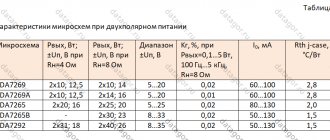
Characteristics of the TDA7388 chip
| Parameter | Test conditions | Meaning |
| Quiescent current | RL = ∞ | 120 - 350 mA |
| Output offset | Playback mode | ±100 mV |
| Voltage surge during on/off | ±80 mV | |
| Voltage Gain | 25 - 27 dB | |
| output power | THD = 10%, Vs = 14.4 V | 26 W (typ) |
| Maximum power output (non-musical) | Vs= 14.4 V Vs= 15.2 V | 41 W 45 W |
| Harmonic distortion | POUT = 4 W | 0.04% (typ) |
| Power supply ripple suppression | f = 100 Hz, VR = 1 VRMS | 50 - 65 dB |
| High cutoff frequency | POUT = 0.5 W | 100 - 200 kHz |
| Input impedance | 70 - 100 kOhm | |
| Stereo separation | f = 1 kHz, POUT = 4 W | 60 - 70 dB |
| Current consumption in standby mode | VST-BY = 0 | 20 uA (max) |
Where it all started
I put up with this for 4 years. One day in the spring of 2022, a friend and I were discussing car audio and he boasted that he had ordered an Android radio from China; it cost him 15,000 rubles. The sound is much better, there is navigation, it looks great. I was very inspired by this. And I also decided to see what China could offer for my car.
It turned out that there are plenty of options. Several appearance designs, different characteristics, different screen sizes, different fillings. After a week of searching, I decided on the model. I had some money saved up and I placed an order.
I will not dwell on the characteristics in detail. At that time, it was the most powerful radio with Android 6 on board, 2 GB of RAM and a 4G modem. Externally, the radio looked very stylish. But most of all I was interested in the sound quality and speed. There was no way to check it at home, I had to wait for the weekend and plan a trip to the garage to install the radio in the car. Because I really didn’t want to drive with a hole instead of a radio if something went wrong.
Finally I waited until the weekend and went to install it. The adventures have just begun! Since the radio was part of the front panel, an air duct, an emergency stop button, an air conditioning control unit, and temperature and fan controls were mounted in its body. First, these blocks had to be removed from the old radio. Everything went smoothly here. But when I started attaching the blocks to the new radio, it turned out that the case had minor casting defects, and the installed elements moved with difficulty, and the emergency stop button was generally jammed. After two hours of work with the help of a needle file, a file and some mother, everything worked as it should. Everything spun, pressed and connected as if from the factory.
Connecting to the on-board network surprisingly went very smoothly. The supplied wires were connected to the standard wiring and everything worked the first time. The joy knew no bounds! The sound pleased me. The standard speakers began to sing in a new way, more richly and bassily. But, as it turned out later, this is in comparison with the old radio. And so I was happy with the new toy for a whole month, until I again met a friend with whom we discussed car audio.
Amplifier circuit for tda7388
The figure shows a connection diagram for the tda7388 chip; capacitor C6 is necessary to regulate the on/off time and plays a significant role in optimizing clicks during transient processes. The minimum capacitance value for such a capacitor is 10 µF.
The input signal is supplied through capacitors with a capacity of 0.1 μF to pins 11,12,15,14 relative to the S-GND ; with such a capacitance, the lower frequency of the medium will be 16 Hz.
the ST-BY or MUTE operating modes, you can use any low-power transistors, or the CMOS output of a microcontroller. RC chains are installed on these pins, which are necessary for smoothing control signals, otherwise control clicks may be heard when controlling the microcircuit. To control pin 22, about 10 μA is needed, so a 70 kOhm resistor is needed.
If there is any noise at the output of the amplifier, then it is necessary to install a first-order low-pass filter at the input, an RC circuit of 1 kOhm + 220 pF.
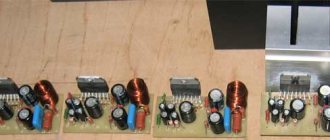
Circuit design of a single-board 4-channel class AB amplifier on the TDA7388 chip
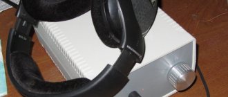
Let's look at the amplifier board vertically from above:
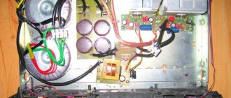
Now let's look at the board itself without a radiator and figure out what's on it for what.
Along the edges on the left and right are terminal blocks for connecting 4 amplifier outputs. If you need to use only two or three outputs, then you don’t have to connect the extra ones, but they cannot be paralleled with “working” outputs to increase power.
There are not many elements on the board.
In the center is a 4700 uF * 25 V electrolyte, which is necessary to smooth out power ripples, prevent self-excitation, etc.
Ceramic capacitors C2, C11...C13 are connected in parallel to each other and in parallel to the electrolyte. Their task is to suppress high-frequency interference and, again, suppress self-excitation.
Capacitors C6...C8 are used to cut off the DC component from the input signal.
Resistor R2 and the LED at the bottom of the board (in the picture) are simply responsible for indicating that power is being supplied.
Electrolyte C4 is a timing device for the smooth on/off functions of the amplifier.
The white two-pin “MUTE” connector is intended for short-term interruption of sound (activated by closing the contacts).
Two white connectors (IN1 and IN2) at the bottom right are inputs for 4 channels, L (left), G (ground), R (right).
A double microswitch above them parallels the LL and RR channels if the signal is not four-channel, but two-channel (stereo). You can listen to it in this mode on as many as 4 speakers (two for each channel, but not in parallel, but each at its own outputs).
The photograph shows the mikriki in the “closed” state.
The white two-pin connector labeled DCout is designed to transfer power from the board to other devices, for example, to a tone control unit or preamplifier.
And finally, the three-pin terminal block at the bottom left, designed to supply power: it has a special feature.
This feature is the third contact, designated REM, which performs the “Stand-BY” function, i.e. transition to “sleep” mode with low consumption. Activated by low level (connection to ground or low level of digital signal). If control of this signal is not required, then it should be connected to the power supply plus.
Important note: the board does not have a “foolproof” diode in the power circuit, and therefore the polarity of the power supply should never be reversed!!!
The diagram for using the microcircuit from the datasheet for the TDA7388 microcircuit is as follows (block diagram and example of a circuit diagram):
The microcircuit is equipped with various types of protection: from overheating, from short circuit to ground or to power, from overcurrent, etc.
Note: the numbering of the “piping” elements on the diagram does not coincide with the numbering on the board.
We won’t consider the rest of the “small things” on the board.
Analogues of the tda7388 chip
Below are microcircuits that have the same pinout (pin-to-pin analogues).
Before changing one microcircuit to another, you should carefully study the factory technical description for compatibility.
| IC | Description | Note |
| TDA7381 | 4 x 25W quad bridge car radio amplifier | Difference: Pin 25 - diagnostics |
| TDA7382 | 4 x 22 W four bridge channels car radio amplifier | Difference: Pin 25 is a clip detector |
| TDA7383 | 4 x 30W quad bridge car radio amplifier | Difference: Pin 25 is a clip detector |
| TDA7384A | 4 x 46W quad bridge car radio amplifier | |
| TDA7385 | 4 x 42W quad bridge car radio amplifier | Difference: Pin 25 - diagnostics |
| TDA7386 | 4 x 45W quad bridge car radio amplifier | |
| TDA7387 | 4 x 41W quad bridge car radio amplifier | |
| TDA7388 | 4 x 45W quad bridge car radio amplifier | |
| TDA7389 | 4 x 45W quad bridge car radio amplifier | difference: pin 25 – clip detector |
| TDA7454 | 4 x 35 W high efficiency quad bridge car radio amplifier | difference: 16 pin - switching modes and 25 pin - clip detector |
| TDA7850 | 4 x 50 W MOSFET quad bridge power amplifier | difference: pin 25 - HSD/OD output |
| TDA7851F | 4 x 48 W MOSFET quad bridge power amplifier | difference: pin 25 - OD output |
| TDA7854 | 4 x 47W MOSFET quad bridge power amplifier | difference 25 pin - clip detector output |
| STPA001 | 4 x 50 W MOSFET quad bridge power amplifier | Only in Flexiwatt25 housing. Difference: Pin 25 – OFFSET DETECTOR OUT |
| STPA002 | 4 x 52 W quad bridge power amplifier with low voltage operation | Only in Flexiwatt25 housing. Difference: Pin 25 – OFFSET DETECTOR OUT |
How it was in practice
Characteristics of transistor s8050
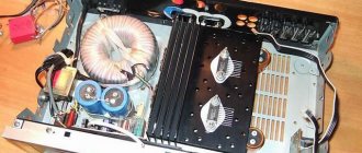
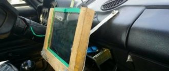
I disassembled the radio. The layout is quite dense. But everything was done carefully.
There are two ways to dismantle the old microcircuit:
1. Carefully desolder each leg. Use a desoldering pump to remove excess solder from the soldering areas. And get the microcircuit. And perhaps it will even work if you manage to avoid overheating the legs. 2. Bite off the legs with pliers and calmly remove one leg at a time.
TDA7850 microcircuits are often counterfeited and there may be manufacturing defects. Those. The prospect of being left without music again did not make me happy, and I decided to take the first path in order to save the old microcircuit. As it turns out later, this was a mistake. It would be better if I bit it and calmly removed one leg at a time. I didn’t have the skills to do this kind of work; it took an hour to dismantle the microcircuit. But we are not afraid of difficulties! The installation of a new microcircuit is ahead. The place for it has been prepared, excess solder has been removed. Another half hour and the new microcircuit is in place.
I'm assembling a radio. While I was assembling it, I tore the cable going to the control buttons a little. I had to trim it a little. In the end, I collected everything and went into the car to check. I connected it, turned on the ignition, the screen lit up. Loading has started. Everything went fine. I turn on the radio, there is no sound. Verdict - the chip overheated during soldering. I'm thinking about what to do next. Install the old radio and look for a new chip, or try to return the old TDA7388. And then I decided to call a friend to ask how the chip replacement went and tell him about my failure.
He says that he decided not to change, because... He’s afraid of ruining the radio, and that he might give me his microcircuit. I was pleased with this turn of events. In the evening I picked up a new microcircuit and began to gather my thoughts for the second time. Dismantling the dead microcircuit went without any problems. I installed the new chip quickly. Fortunately, my hand is already full! All that remains is to assemble and check. Everything came together without problems. And here I am sitting in the car and turning the ignition key. Loading has begun. I turn on the radio..... Singing!
The sound was really good! Clear bass, rich sound picture! I thought the result was worth two days of suffering. This is victory! I turn off the ignition, get out of the car and a delicious FART is heard from the speakers! More precisely, a click. It was like a shot to the head. The strength was running out. I didn't understand what went wrong. But there was nothing to do, I left everything as it was. I stuck the radio in place and went to read what to do next. On the forums where I read about remaking the radio, they couldn’t help me.
I drove around for a week with a clicking radio. Moreover, the click appeared after the ignition was turned off and the radio was de-energized. Forums are good, but here we need heavy artillery, and I decided to stop by the nearest service center for repairing household appliances. I talked to the service engineer, explained the situation and he suggested where to look for the problem. It turns out that such a click is heard when the MUTE channel is not connected to the amplifier chip. And most likely I damaged the track on the board when I changed the microcircuits. Since the process of removing/disassembling the radio is quite time-consuming, I had to wait for the weekend again. In the end, my guesses were confirmed. The path was very thin and I simply did not notice how I damaged it. I restored the track by carefully soldering a thin wire to the leg of the microcircuit and the connection point of the MUTE channel. The radio worked as it should!
As a result, if I knew that I would have to disassemble and reassemble it 6 times, I probably would not have decided to replace it. But the choice has been made, and now I can share my experience. A year later, the Chinese began to produce radio tape recorders with good amplifiers, the main thing is that the TDA7580/7581 amplifier chip is indicated in the description. By the way, radios with the TDA7388 chip are installed on Lada Vesta. Replacement is also possible there.
Do you want to take part in the competition? Click HERE.