Amplifier power calculation for dummies
Fireworks to everyone!
I am new to Hi-Fi and am currently choosing my first serious 5.0 speaker system. I've read quite a lot on this forum and often come across the expression "this amplifier/receiver will not drive these speakers", "it's too weak for your room", etc. I decided to try to calculate the required amplifier power, let's go)
The maximum permissible sound pressure level for a person is 100 dB (much louder than a subway car), an adequate person will not listen to music at such a volume in an apartment, most likely the maximum for an apartment is 80-85 dB (and even then the neighbors will complain). 85 dB is the volume in a movie theater. 97 dB is the plus/minus volume of a subway car.
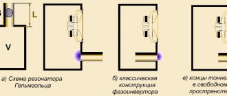
We take speakers with a sensitivity of 91 dB, i.e. This is the sound pressure level at a distance of 1 meter from the speakers with a supplied power of 1 W. We will listen to music away from the speakers - 3 m from them, after these 3 meters the sound pressure level will drop by 9 dB. Those. to listen to a “subway car” we need the speakers to produce 106 dB.
We count watts: “when the volume increases by 3 dB, you need to double the power supplied.” Those. for a level of 91 dB - you need 1 W, for 94 dB - 2 W, 97 dB - 4 W, 100 dB - 8 W, 103 dB - 16 W, 106 dB - 32 W. Those. To listen to a “subway car” while sitting three meters from the speaker, we need to supply 32 W of power to the speaker.
As I understand it, almost all cheap receivers are class D amplifiers; If you believe Google, then the efficiency of such amplifiers is 90-95%, but I have a hard time believing this, let’s round the efficiency down to 80%. Those. in order to supply 32 W to the speaker, the receiver must consume 40 W of electrical power. We multiply by 5 channels (although you don’t need that much for the rear and center channels), we get 200 W of power consumption.
And now we look at one of the cheapest receivers on the market - Yamaha RX-V483, its power is 260 W. It turns out that under design conditions it works at 75%. I understand that this is quite a lot - nonlinear distortions and all that, but excuse me - this is the maximum maximum in terms of sound level, no one ever listens to music like that. And if we take the real volume level (85-90 dB), then the calculation for it will show the required electrical power for 5 channels at 25-30 W , and this will be enough for any amplifier.
So I come to the conclusion that ANY receiver/amplifier is enough for an apartment. And in terms of quality, it is quite difficult to distinguish one class D amplifier from another class D amplifier (this is almost “digital” amplification). If we want a real improvement in quality, then it makes sense to take a class A amplifier, for example. But its efficiency will already be significantly lower (10 percent), and therefore power is much more important here, but accordingly the price rises so much that the average person will not even look at such amplifiers).
Where did I go wrong in my calculations? What did I miss in calculating the required amplifier power?
The amplifier's own noise.
What is noise?
In electronics, noise refers to random fluctuations in signal amplitude that dampen the useful signal. This also includes various types of interference. An amplifier's own noise is noise that originates both inside the amplifier itself and can be caused by an external source of interference or poor-quality power supply to the amplifier. Let's look at the main types of amplifier noise.
Background
This noise is caused by poor quality power supply to the amplifier. If the power supply is assembled on a network transformer, then the noise will be at a frequency of 100 Hz (2x50Hz, according to the diode bridge circuit). That is, at the output of such an amplifier we will hear a hum if we connect a speaker to the output. I think you have often heard the expression “the speakers are making noise.” That's all from this series.
Interference and interference
These may be external sources that somehow affect the amplifier. This could be interference from a 220 Volt network (very often you can see it if you just touch the signal probe of an oscilloscope), it could also be some kind of spark that forms in the spark plugs of internal combustion engines.
A small lyrical digression. I remember watching Disney cartoons on Channel 1, and across the road my neighbor was sawing wood with a Druzhba-2 chainsaw. Then there was such interference on the TV screen that I silently swore at my neighbor.
Well, what about without lightning discharges? Thanks to the electromagnetic pulse, we have such an invention as radio.
Sources of interference can also include radio and TV stations, nearby and standing electrical equipment, such as powerful switching mechanical switches, arresters, etc.
And of course, this is the noise of the radio elements themselves. This includes thermal noise (Johnson noise), shot noise, and flicker noise.
The most significant is the noise that occurs at the amplifier input in the very first stage. This noise is further amplified in the same way as the useful input signal. As a result, at the output of the amplifier, both the useful signal and the noise signal will be amplified. Therefore, when designing high-quality amplifiers, they try to minimize the noise at the input of the first amplifier stage as much as possible.
Distortion introduced by the amplifier
Distortion is determined by comparing the waveforms at the input and output. The ideal amplifier is one that exactly repeats the shape of the signal applied to the input. But since our world is not ideal, and radio elements are not ideal either, the output signal will always be slightly distorted. The main thing is that these distortions are not so critical.
Basically, distortions are divided into 4 groups:
- Frequency
- Phase
- Transitional
- Nonlinear
Frequency distortion
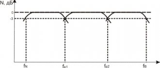
Frequency distortion occurs due to the fact that the gain is not the same throughout the entire frequency range. Or in simple words, some frequencies are amplified well, and some are poorly). To understand this, just look at the frequency response of the amplifier.
In this case, we can see that the low and high frequencies will be amplified less than the mid frequencies. And since a complex signal consists of many frequency components, frequency distortions will arise as a result.
Phase distortion
Phase distortion occurs due to the fact that different frequencies with different time delays appear at the output of the amplifier. Some frequencies lag more, and some less. Let's look at all this using two pictures as an example.
Let’s say we “drive” a sinusoidal signal with a low frequency to the input and at the output we get an already amplified signal, but with a slight delay.
But also do not forget that coils and capacitors are frequency-dependent radio elements. Their reactance depends on the frequency of the signal, therefore, driving a signal with a different frequency through an amplifier, we will get a completely different signal delay
That is, in our case t1 ≠ t2. Is it good or bad? If we amplify the sinusoid, then in principle we don’t care. What difference does it make before it appears at the exit or later? The main thing is that the signal will be amplified.
Everything would be fine, but it is worth remembering that complex signals consist of the sum of many sinusoids of different frequencies and amplitudes.
To understand what the sum of signals is, it is enough to consider the following examples:
well, and one more, I don’t mind)
We add the amplitudes at the same times and get the sum of these two signals.
And this is how a rectangular signal is formed from different sinusoids of different frequencies:
In this case, we are trying to “assemble” a rectangular signal from the sum of sinusoids of different amplitudes and frequencies.
But since our amplifier delays different signals at different frequencies, we have discrepancies between the signals. This is best explained by the picture below. We have two sinusoidal signals with different frequencies and amplitudes:
If we add them up, we get a complex signal:
But what happens if the second signal is out of phase relative to the first?
Now let's look at the sum of these signals:
A completely different signal! Do you feel the difference? The phase was slightly shifted, but the signal shape had already changed.
That is, at the output of the amplifier we wanted to get this amplified signal:
and got this:
As a result of phase distortions, our complex signal, consisting of two sinusoids, changed its shape. At the output of the amplifier we received a completely different signal. And as you remember, the role of an amplifier is to amplify the signal while maintaining its shape .
The phase-frequency response (PFC) of an amplifier is a graph of the phase angle introduced by the amplifier as a function of frequency. It might look something like this:
Where
φ is the phase shift relative to the input and output signal
f - signal frequency
The human ear does not notice phase distortions, despite the fact that even the shape of the signal changes. Therefore, when designing audio amplifiers, phase distortion is not taken into account.
Frequency distortions and phase distortions are classified as linear distortions, since both types of distortions are caused by linear elements of the circuit. Scientifically speaking, no additional harmonics appear in our signal spectrum.
Transient distortion
Transient distortion is the distortion of a rectangular pulse that is fed to the input of the amplifier. At the output, such a pulse will have a different shape, caused by signal distortion inside the amplifier itself.
To evaluate transient distortions, the transient response is used. It represents the dependence of the voltage or current at the output of the amplifier on time from the supply of a rectangular pulse to its input.
In the figure below we have a rectangular signal, which is fed to the input of the amplifier, and at the output of the amplifier there will already be a distorted amplified signal. This distortion is caused, as usual, by the presence of reactive radioelements in the amplifier circuit, that is, the same inductors and capacitors.
To evaluate transient distortions, the following parameters are used:
Um is the amplitude of the pulse, measured from the flat top of the pulse, V
ΔUв is the surge of the pulse front, V
ΔUс — decay of the top of the pulse, V
The following two parameters are measured in the range from 0.1Um to 0.9Um:
tf - duration of the pulse front
tc — pulse decay duration
And the duration of the pulse itself is measured at the level of 0.5 Um.
Signal to noise ratio
Suppose you have a TV at home that receives analogue broadcasts. On the TV screen we see a clear picture:
But suddenly the antenna on the roof of your house, due to strong wind, deviated a little to the side and the image deteriorated
Then the antenna completely fell from the roof, and on the TV we now see something like this
In which case will the signal-to-noise ratio be greater and in which less? In the first picture, where there is a clear image, the signal-to-noise ratio will be very large, since not in the first picture we cannot catch any interference in the image with a simple glance, although in theory there is some).
In the second picture we see that there are noises in the image that make viewing the picture uncomfortable. Here the signal-to-noise ratio will be much lower than in the first picture.
Well, in the third picture the noise almost completely overpowered the image. In this case, we can say that the signal-to-noise ratio will be very small.
The signal-to-noise ratio is a quantitative, dimensionless quantity.
In analog electronics, for the amplifier to operate normally, the useful signal must be several times higher than the noise, otherwise this will greatly affect the quality of the amplification, since the useful signal is added to the noise.
The signal-to-noise ratio in English literature is referred to as SNR or S/N.
Since sometimes this ratio reaches very large values in numbers, it is therefore most often expressed in decibels:
Where
Usignal - root mean square value of the useful signal, V
Unoise - root mean square value of the noise signal, V
Psignal - signal strength
Pnoise - noise power
That is, in our case with the cat in the first picture, the amplitude of the useful video signal was many times greater than the amplitude of the noise, so the first picture was clear. In the third picture, the amplitude of the useful video signal was almost equal to the amplitude of the noise, so the picture turned out to be very noisy.
One more example. Here is a sine wave with SNR=10:
But the same sine with SNR=3
As you may have noticed, a signal with SNR=10 is much “purer” than with SNR=3.
SNR is most often seen when describing the characteristics of an audio amplifier. The higher the SNR, the better sound quality the amplifier will have. For HI-FI sound systems this figure should be 90 dB and above. For telephone conversations, 30 dB is quite enough.
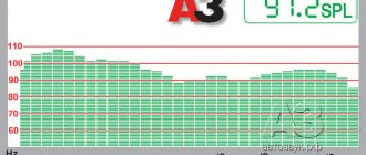
In practice, SNR is measured at the output of the amplifier using a millivoltmeter with trueRMS, or using a spectrum analyzer.