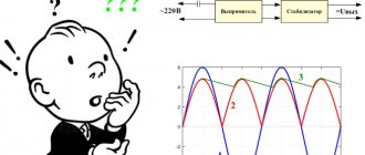
Despite the popularity of ULFs operating in class D, classic microcircuits such as TDA7266, TDA7297, etc. have not exhausted their service life.
Because of their simplicity, such amplifiers are very suitable for beginner radio amateurs who want to assemble something WITH THEIR OWN HANDS. There are a lot of reviews on the Internet about these and similar chips in the “junk and rubbish” style. Are they fair? Is it the chips or the “masters”? Why are different capacities indicated everywhere and what does it depend on? Is it possible to do a “double bridge” to get even more power?
I will try to answer these questions.
Contents
- 1 UMZCH TDA7266, TDA7297 do not work from Krona!
- 2 About the output power numbers in the datasheet
- 3 Amplifier circuit based on TDA7266, TDA7297 with ground sharing
- 4 Differences between TDA7266, TDA7297 chips 4.1 Different packages
- 4.2 Different Gain 4.2.1 Volume Control
- 4.2.2 Tone corrector
- 5.1 Electrical characteristics of TDA7297 at 8.2 Ohm load
- 7.1 UMZCH board with Ali
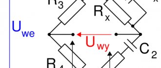
ULF circuit
Circuit from the TDA7297SA datasheet
A more beautiful color scheme option
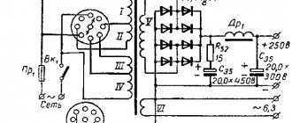
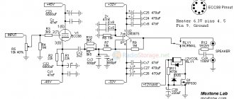
The power circuits are connected to a car battery or to a 12 volt stabilized power supply. The positive contact goes to pins 3 and 13, and the minus contact goes to 8 (GNDP - power supply ground) and 9 (GNDS - audio signal ground). The left and right stereo inputs are connected to pins 4 and 12 respectively via 2.2 µF filter capacitors (to remove the DC component of the signal). The soft start is performed using 47k resistors and a 10 uF capacitor.
Printed circuit board
The current consumption in standby mode is about 50 mA, and during St-by shutdown it is about 100 µA.
↑ UMZCH TDA7266, TDA7297 do not work from Krona!
Often there are complaints in the spirit of “it is indicated that the microcircuit runs on 6 Volts, but I connected a Krona battery with as much as 9 Volts, and the amplifier does not work, which means it sucks.” Do I need to comment? The crown doesn't work, you need a good power supply with sufficient current carrying capacity.
Today, a miniature UMZCH board is a common thing, but it won’t be possible to make a tiny ULF on it because you need a fairly powerful power supply and other wiring. And the power supply has dimensions much larger than the UMZCH board. There is no need to talk about a classic transformer power supply, especially since large power filter capacitors are needed.
With switching amplifiers, things are not so simple either. Cheap flyback power supplies can be a source of interference; it makes sense to move them outside the case, as in laptops. So, the power supply must be powerful enough and not cause interference.
Related materials
3500 low-frequency power amplifier microcircuits and their analogues. E. F. Turuta... 3500 low-frequency power amplifier microcircuits and their analogues. E. F. Turuta Publisher: DMK...
Object "Pipe". A mystery!... Whoever guesses what this space thing is, nothing will happen to him. Write your guesses to...
5000 modern ULF microcircuits and their analogues. E.F. Turuta... 5000 modern ULF microcircuits and their analogues. E.F. Turuta Publisher: Science and Technology Year of publication:…
TDA7265… 25+25 Watt stereo amplifier with Mutam and Standby. Can be turned on in a bridge. Protection against short circuit and overheating….
Modern amplifiers on microcircuits. Bashirov S.R…. Modern amplifiers on microcircuits. Bashirov S.R. This publication discusses the design of units...
Microcircuits for switching power supplies and their application... I would like to bring to your attention the reference book “Microcircuits for switching power supplies and their...
Audio amplifier TDA7265 2x25W. The “Pipe” object is the answer... There was a bit of a false start with the riddle: I sent Igor a photo with the question “is it worth writing about this...
TDA1514A: 50-watt amplifier in 15 minutes... One of the developments - the TDA1514A chip - can help create a Hi-Fi amplifier...
Protecting USB devices from static. Chips TPD2E001, USB6B1, STF202-22T1G... Probably each of us has ever experienced a discharge of static electricity, and many...
Amplifier on a chip TA8205, TA8210, TA8215, TA8221... A very short practical article with photos, inspired by the project of our Bulgarian friend in...
↑ About the output power figures in the datasheet
Further.
You can't ask these (and other) amplifiers to do more than they can. Don't trust advertising promises too much. The power stated in the datasheet is usually exaggerated. That is, this is a deception, but formally everything is correct. It is written that such and such power is at 10% distortion or even with a meander. This is true, but it is impossible to listen with such distortion - your ears will wither. Honest power - with distortion no more than 1...2%, and for these amplifiers it is 25...30% lower than with distortion of 10%. You need to look at what load the amplifiers can operate with - 8 Ohms, 4 Ohms or even 2 Ohms. If an amplifier can drive a 2 ohm load, it can always drive a 4 ohm or 8 ohm load, but not vice versa.
I’ll get ahead and write that the TDA7266, TDA7297 microcircuits are capable of sounding stationary acoustics (there will be no disco), but this is not their profile. Their profile is bookshelf, computer, portable acoustics, including battery-powered ones.
↑ Sources mentioned
Stereo audio amplifier on TDA2616 chip Audio amplifier TDA7265 2×25W
Object “Pipe” - the answerTDA7265TDA7265TDA7265BTDA7269ATDA7292Thank you for your attention!
Vladimir Mosyagin (MVV) Russia, Veliky Novgorod List of all articles
MVV profile
I became interested in amateur radio from the fifth grade of high school. My diploma is radio engineer, candidate of technical sciences. Author of the books “For a young radio amateur to read with a soldering iron”, “Secrets of amateur radio craftsmanship”, co-author of the series of books “To be read with a soldering iron” in the publishing house “SOLON” -Press”, I have publications in the magazines “Radio”, “Instruments and Experimental Techniques”, etc.
↑ Differences between TDA7266 and TDA7297 chips
↑ Different cases
According to the information sheet, the microcircuits are completely interchangeable, but in fact it turned out that the TDA7266SA is in the CLIPWATT15 package, and the TDA7297 is in the Multiwatt15 package.
Different fastenings, different lead lengths, different housing thicknesses. Therefore, the lay file contains two options for the board design.
↑ Different gain
I will mention another important, but subtle difference between the TDA7266 and TDA7297 - sensitivity. The first has a gain of 26 dB = 20 times, the second has 32 dB = 38 times (tested). With a 12 V supply and a 4 Ohm load, to achieve full undistorted power, 6V/20=0.3V must be applied to the TDA7266 input, and 6V/38=0.16 V must be applied to the TDA7297 input. This leads to two important conclusions.
↑ Volume control
1. A volume (level) control is required at the UMZCH input, even if the signal is supplied from a computer or similar source with its own output signal level control. Indeed, severe overload is more than likely and adjusting the volume only at the signal source will be extremely inconvenient due to the narrow range. It is better to install the RG on the UMZCH in a position where the maximum power will be at the maximum output level of the source. Of course, this applies to all such UMZCH. I advise you to use resistors for the RG of no more than 50 kOhm, and preferably 10...22 kOhm.
↑ Tone corrector
2. I think that the optimal sensitivity is UMZCH = 0.5 V. You can take advantage of the sensitivity reserve by installing a tone corrector at the input (you can call it a loudness compensation, etc.). I took the simplest filter, known from tube times, and modified it a little. I'll give you a diagram.
In the “upper” position of the switch there is a rise in bass and treble, in the “lower” position the frequency response is flat.
Unlike the “primary source”, a small smooth rise begins at HF above 6 kHz, and at LF below 150 Hz. This should somewhat compensate for the decline in small-sized speakers for which this compensator is intended. Let me remind you that in almost all “adult” and expensive bookshelf speakers, the decline starts at 100 Hz. By ear, the sound with this corrector is preferable.
The passive filter reduces the sensitivity by about 6 times and instead of 0.16 V we get 1 V. This is not enough, but in most cases it will be enough. I'm going to adjust the tone corrector using SpectraLab, but I don't have time yet.
I am going to add a peak overload indicator to the amplifier, I think that this is useful and will allow me to determine “who is to blame” and “what to do.”
↑ Normal and bridge connection TDA7266, TDA7297
Let's take a look at what and how you can get from a regular and bridge exit.
In Fig.
a ) it is clear that with a 12 V supply at the amplifier output, the instantaneous voltage can ideally be from +12 V to 0 V; in this case it is simply impossible to go beyond the power supply limits. This voltage is supplied to the “+” terminal of the speaker. And the speaker output “-” is always tied to half the power, i.e. 6 V.
In Fig. b)
This voltage is shown in red. The amplitude of the sine wave Ua will ideally be up to 6 V. According to the formula, it turns out that the power of an ideal amplifier into a 4 Ohm load will be 4.5 W (at 8 Ohms up to 2.25 W, at 2 Ohms up to 9 W, but a 2 Ohm load is too heavy for most amplifiers). In practice, it is rarely possible to get even 4 W at 4 ohms without large distortions.
In Fig. V)
the usual output of an amplifier with single-supply power is shown; for clarity, the speaker and coupling capacitor have “swapped places”. Without a signal, the output of the amplifier is half the power, i.e. 6 V. Through the low resistance of the speaker, the capacitor is charged to the same voltage and without a signal, no current flows through the speaker.
When a sinusoidal signal is applied, the instantaneous voltage at the output of the amplifier will change from 0 to 12 V, but at the “-” terminal of the speaker a constant voltage of 6 V will be maintained and the entire voltage change will be applied to the speaker since at audio frequencies the resistance of the speaker is many times higher than the resistance capacitor (this condition will be violated at the lowest frequencies, which is why capacitors with a capacity of thousands of microfarads are installed here).
Instantaneous changes in voltage at the output of the amplifier are not enough to change the voltage on the capacitor; its charge is too large, it has a large “inertia”. There will be alternating voltage on one terminal of the speaker, and only constant voltage on the other.
To sharply increase the power, a “bridge” connection of the load is required; a pair of identical amplifiers, but operating in antiphase, is needed. Potentially the power output can increase by 4 times! In practice, everything is not so rosy; there are a number of problems. In Fig. G)
such a connection is shown. You must understand that you can’t jump beyond the power supply here either; you can’t get a voltage higher than the supply and/or lower than zero at the output of the amplifier (the same applies to bipolar power supply).
The trick here is that now BOTH speaker outputs will receive an alternating amplified signal voltage and go in “different directions”. Thus, the amplitude of the instantaneous voltage doubles. This doubling results in quadrupling the power.
In Fig. G)
at points A, C, E at outputs 1 and 2, half the power, i.e. 6 V, on the speaker the voltage is zero.
At point B on pin. “+” dynamics +12 V, on pin. “-” 0 V. This means that 12 V is applied to the speaker. At point D there is also 12 V, but of reverse polarity. So from a 12 V source they get a full swing AC voltage (double amplitude) of 24 V! Ua also doubled and amounted to 12 V ( Fig. e
). According to the formula, the output power will no longer be 4.5, but 18 W. Jump "over your head."
From this it is clear that there can be no “double bridge” (which many people dream about)
because at any point in the circuit there cannot be a voltage that goes beyond the power source. In our case: 0 and +12 V.
↑ How else to increase the power of UMZCH?
How else can you increase the output power?
There are several ways, for example, a 2 Ohm load. But in practice this is difficult - the currents become large, they must be provided by the output stages of the amplifiers. Losses on wires, etc. increase sharply. The method works, but not in our case. You can use... an output transformer, like in tube amplifiers, but on the contrary, not a step-down transformer, but a step-up transformer. Theoretically, you can get any power, but I have not seen this used in practice.
The most convenient way is a step-up supply voltage converter (Step-UP DC-DC). Then the supply voltage restrictions are removed.
By the way, you can connect 4 speakers to such amplifiers, but in this case you will need high-capacity output capacitors. You should pay attention to the polarity of connecting the speakers. Let's look at the example of TDA7379.
I see the advantage of such a connection in that the capacitors will protect the speakers in the event of a breakdown of the microcircuit.
Tsokolevka
The TDA7294 chip is manufactured in a MULTIWATT-15 plastic package. Its newer modification is TDA7294SA in monolithic plastic packaging CLIPWATT-15. Both amplifiers are mounted vertically on the board, with mandatory attachment to the radiator. You can see the pinout in the figure below.
The metal substrate of the microcircuit in the MULTIWATT-15 case is connected, when mounted on a board, to the power supply minus.
Let's list the purpose of the TDA7297 pins:
- 1 and 2 (OUT1+ and OUT1-) – outputs to the first speaker;
- 3 and 13 (VCC) – supply voltage (from 6 to 18 V);
- 4 and 12 (IN1 and IN2) – input signal to the first and second speakers, respectively;
- 5, 10, 11 (NC) – not used;
- 6 (Mute) – pin designed to control the input signal;
- 7 (St-By) – switching the microcircuit to sleep mode;
- 8 (PW-GND) – power supply minus;
- 9 – (S-GND) – minus input signal;
- 14 and 15 (OUT2- and OUT2+) – to the second speaker.
↑ Measurements
So, the amplifiers are assembled and the power is connected.
No adjustment is required, but you need to make sure that the constant voltage on all amplifier outputs is equal to half the supply. I assembled several ULFs on the TDA7297 and TDA7266SA,
I powered them from a laboratory power supply, determined the maximum output signal using an oscilloscope at the limiting threshold, here are the tables with the results.
↑ Electrical characteristics of TDA7297 at 8.2 Ohm load
Here Usupply is the voltage of the power supply, Isupply.
— current from the power supply according to its indicator. U load — load voltage. P load — load power. U amp. — amplitude of the output voltage (for comparison with the ideal graphs above). I ampl. — current taken from the output transistors. So, with a 12 V supply, 6.3 W of undistorted power was obtained instead of the theoretical 9 W. 1.5 times less or 3 W less. Few? But compared to the “ideal” 2.25 W with a non-bridged output, it is almost 3 times more.
At 15 V the power is already 10 W. But what about the stated 15+15W DUAL BRIDGE promised in the datasheet? But this is advertising. Even on the datasheet graph, with a maximum power supply of 18 V, 14 W are received. The “electrical specifications” indicate that 18 V is the maximum permissible voltage. True, it is indicated elsewhere that the absolute maximum power supply is 20 V, I think that here 15 W will be received, but this is already “beyond the bounds”. And this is for genuine microcircuits.
Similar experiments on microcircuits with Ali will most likely end in profanity.
In general, the graph of the dependence of output power on supply voltage for my microcircuits coincides with that given in the datasheet. The information sheet states that the microcircuits have a bunch of protections against short circuits, overheating, and, among other things, there is a limit on the output current at 2 A, remember this and note that in the table above the maximum current is 1.59 A, i.e. it does not reach to the limit. I think the developers chose 2 A for a 16.5 V supply and an 8 ohm load.
↑ Electrical characteristics of TDA7297 at 4.1 Ohm load
What happens if the load is 4 ohms? It's tempting to double your power output. In the datasheet all measurements are at 8 ohms. Will it burn or not (I’m sure that Ali’s chips don’t have much protection)? In addition, limiting the current at 2 A will not allow you to get double the power at 4 ohms. I was waiting to see this on the oscilloscope screen and... I didn’t see it. Here are the results.
The power was squeezed out more, but not twice, but by 30...40%.
Why? At higher currents, losses in the microcircuit itself increase. I think you guessed that if the load is reduced to 2 ohms, then the losses will increase even more, but for these microcircuits I won’t even try. It is also interesting that the current without restrictions was 2.5 A. Whether there is protection in the chip and how it works is unknown, and I don’t want to burn the chips on purpose. I feel sorry not for them, but for my time.
With a proprietary chip, we would get no more than 7.5 W due to current limitations. I think with a 16.5 V supply you can get about 15 W at 4 ohms, but the heating of the microcircuit will increase and a good heatsink will be required.
Why did I take measurements with an 11V supply? And this is battery powered - three Li-Ion cells. When fully charged, they will give 12 V, and when discharged to the standard 3.6...3.7 V, they will give just 11 V. You can estimate the maximum power from the “batteries”. More than 5 Watts into 8 ohms and about 9 Watts into 4 ohms from a small portable balalaika is not too bad. At the level of good portable radios of the past.
In my opinion, using these microcircuits with a power supply below 9 V is impractical, but with 3 or 4 18650 elements, it is quite possible. With a power supply of 12...16 V there will even be a power reserve.
↑ Graph of real modes
For greater clarity, consider again the graph of real, rather than ideal, regimes.
The “left” pair of transistors is the output of the first amplifier, the “right” pair is the output of the second.
Pale gray transistors are closed, black ones are fully open. Drawings for points A and B of a sinusoid. The current always flows only in one direction from the “+” supply to the “-” supply, but by cleverly controlling it, you can obtain an alternating voltage, and even with a full amplitude higher than the supply voltage. The voltage drop across transistors depends on the current, the element base, circuit design, etc. Here it is about 1 V. This is not much, but even this reduced the power from the ideal 9 W to the real 6.3 W.
Another note. Unfortunately, there is no normal internal diagram of the microcircuits; there is a slightly more detailed description of such a microcircuit.
I think that the virtual common wire (the audio input signal passes through it) is connected to the common wire at the input through capacitor C1 according to the circuit of the TDA7297 and TDA7266SA amplifiers, so its quality also somewhat affects the sound.
It turned out that my TDA7266SA microcircuits work normally only at voltages above 8 V, below this threshold the sine turns into a triangle, and then quickly “shuts up”. I was sure that I needed to adjust the R1R2 divider and everything would work out, to my surprise, nothing changed.
I do not provide tables with measurement results because they almost coincide with the TDA7297. At the same time, the datasheet states that the TDA7266SA operates from 3.5 V, and the TDA7297 from 6 V. In fact, the opposite is true - TDA7297 operate from 3 V (of course, there is no point in using them in this mode). This is another stone in the garden regarding the authenticity of both microcircuits.
But the power and efficiency graph of the TDA7297 practically coincides with the proprietary one, they work normally with a 4 Ohm load, so the copy turned out to be quite good, the TDA7266SA is somewhat worse, although at a supply voltage of 12...15 V they work fine. In general, I can recommend buying kits for assembly on the TDA7297.
↑ About sound
Of course, they are inferior to audiophile amplifiers.
But the sound is without obvious distortion and not annoying. All frequencies are reproduced, especially low ones. But the sound seems to be purified, simplified, smoothed out. There is no “air”, “liveness” and microdynamics. But the disadvantages when listening to high-quality recordings turn into advantages when listening to MP3s and corresponding acoustics. The detail and transparency of higher-end amplifiers can only highlight the MP3's shortcomings.
I have my own “standards” for determining power (I was surprised to actually find confirmation on some datasheets), my own “musical” power, but it is fundamentally different from the bloated PMPO. For these amplifiers, my power rating is 1...2 W, and this is enough for home listening on acoustics with a sensitivity of about 90 dB.
↑ Printed circuit boards for TDA7297 and TDA7266SA
Today on Aliexpress you can buy both assembled modules based on these chips and kits for do-it-yourself soldering. They cost approx. 1 dollar, a stereo amplifier for that amount is not bad.
↑ UMZCH board with Ali
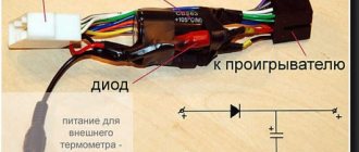
I consider the board in the kit for a dollar on Ali to be successful, you just need to replace the diode with a jumper.
It’s quite a suitable option, but I don’t like everything about it, as I usually think that the boards I wired for my parts are better.
↑ My printed circuit boards
Since I build boards slowly and for a long time, I first decided to make a working breadboard and evaluate whether it makes sense to continue.
I didn’t like the drawings available on the Internet because the traces go behind the back of the microcircuits, the board will not allow you to screw the transistor to the radiator, the radiator will stand on the board. It will be impossible, for example, to screw the board to the amplifier body. I think it's better to solder the common wire jumper to the bottom of the board.
In the amplifier, you should not place ceramic capacitors in the sound path; film capacitors are needed. They take up more space on the board, although the distance between the pins is 5 mm like ceramics.
I also separated the power supply minus and the common input wire through resistor R3. This is not necessary, but then you need to make a board, exactly like in the datasheet. In boards from the Internet, the common wire is usually routed incorrectly. How critical this is is an open question, but in my boards, when powered by a stabilizer, the background is completely absent, and the noise from the high-frequency speaker is barely audible if you put your ear to it.
↑ Let's move on to solving technological issues
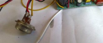
Many people are confused by the power supply and reliability of the mute and stby circuits. Agree, keeping two power poles on one toggle switch is simply dangerous, especially if the toggle switch is more than budget. More than one microcircuit has failed due to such tricks. I also took care of ensuring the reliability of this unit by placing a 12V parametric stabilizer, shown in the figure, directly on the printed circuit board.
Stabilizer
The service circuits of the microcircuit are powered from it. A three-pin jumper is installed as outputs. This allowed us to solve several problems at once:
— If control of the microcircuit is not needed, it is simply fixed in the Play! position, the amplifier is constantly in an unlocked state and is ready for work every second. — If, say, the rear channels are not used in a multi-channel amplifier for a long time, you can throw the jumper to the Mute position, while the input and output stages of the microcircuit will be blocked and its consumption will be reduced to microscopic standby currents.— An external ON-ON toggle switch, such as the available MTS102, can be connected to the jumper.
The diagram also shows an example of a microcircuit power indicator, assembled using R14 LED1 elements. R14 acts as a current source of approximately 5mA for LED1, which lights up in the Play position! and goes out in Mute mode. In addition, even if the toggle switch malfunctions and its +Up-Ground contacts are closed, nothing bad will happen, since the current is limited by resistor R11 at a safe level. The C11 C12 capacitances are doubled compared to standard ones to provide greater turn-on delay and prevent clicking in the speakers even during long-term charging of the power supply.