Household AC Power Supplies
I warn you right away: I deliberately will not touch on switching power supplies here.
This is a topic for another conversation. Generally speaking, the functions of a power supply for low-voltage electronic equipment are usually the following: to provide a specified voltage at the output of the power supply for a given range of current consumption. That is, to put it formally, the power source is a source of constant voltage Uout
, which maintains
Uout=const
when the consumed current changes from
Imin
to
Imax
.
In a “classical” linear power supply, this usually happens like this: the input mains voltage is stepped down using a transformer, then this voltage is rectified and finally stabilized using a linear stabilizer.
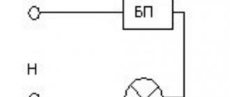
The block diagram of a “classical” linear power supply is shown in the figure below. One of the most “inconvenient” parts of such a power source is the transformer: it is expensive and bulky.
Therefore, radio amateurs and radio professionals were looking for ways to get rid of this bulky and expensive part - the transformer, or at least reduce its size and cost.
And such a solution was found: they began to use the reactance of the capacitor Rc in order to “quench” the excess voltage. Block diagram of a “transformerless” power source ( BIP
) is shown below.
As you can see, the structure of the BIP
almost no different from a classic linear power supply.
Unless instead of a transformer they installed a quenching capacitor. Do not be confused or deceived by the similarity of the structure of these power supplies in the figure: there are a lot of differences inside
.
Advantages of BIP
: it is relatively compact, reliable, cheap, and is not afraid of a short circuit at the output.
But there are also significant disadvantages: it is dangerous from the point of view of a person touching the elements of the powered device. And the maximum current that such a power source can provide is only a few hundred milliamps. At higher currents, the dimensions of the capacitors are large and it is easier to install a transformer or even install a pulse generator.
Based on the advantages and disadvantages of BIP
, its scope of application is well-insulated low-power devices powered from a household electrical network: single-standing sensors, lighting control devices, devices for turning on ventilation and heating, and other low-power devices operating autonomously.
Let's try to understand how a real BIP
and how to calculate it.
Transformerless power supply for LEDs
The essence of such a unit is to use a ballast (quenching) capacitor. On our website there is a detailed article about such a power supply, in which you can find a calculator for calculating the capacitor. In general, the scheme looks like this:
This option has a lot of disadvantages:
- No output voltage stabilization;
- no galvanic isolation (transformer);
- There is no discharge resistor on the ballast capacitor, so there is a risk of electric shock from C1.
Having accepted these shortcomings and modified the circuit, we get the following transformerless power supply for 12V LEDs.
Instead of D1, the L7812 linear stabilizer microcircuit, any other one can be installed at the required voltage (7805, etc., as well as domestic KREN stabilizers).
An alternative version of the power supply circuit for an LED strip, when assembling it yourself, is to use a zener diode or a parametric stabilizer made of a zener diode and a transistor instead of a linear stabilizer. The advantage of this solution is the flexibility in setting the stabilization voltage, because if you do not have a suitable zener diode, you can connect the other two in series and achieve the desired voltage value.
To make a homemade power supply for an LED strip, a domestic zener diode of the D818D series, designed for a voltage of about 12-13 V, is suitable.
Another way of stabilization is to assemble a current stabilizer using two transistors. The stabilization current is set by resistor R2.
R2 = 0.7 * Ist; R1 = 3.9 kOhm.
The current stabilizer strives to produce a given current; this is the best option for transformerless power supply of individual LEDs.
Theory of practice and practice of theory
An example of the simplest practical circuit
Since earlier, before the advent of cheap “switching” devices, power supply units
power supply voltage supply
circuits in books and on the Internet are a carriage and a small cart. But the operating principle of almost all circuits is approximately the same: one or more quenching capacitors at the input, a rectifier and an output constant voltage stabilizer.
Let's look at one of the simplest working BIP
, which is shown in the figure below.
All the main parts of the circuit are immediately visible: quenching capacitor C1
;
full-wave rectifier - diode bridge VD1
and smoothing capacitor
C2
;
voltage stabilizer - zener diode VS1
;
and, finally, the load - a device Rн
.
Let's forget about the “extra elements” or the “basic BIP formula”
For simplicity, let's forget for now about the existence of resistors R1
and
R2
: we will assume that
R2
is absent altogether, and
R1
is replaced by a jumper. For all calculations this is not significant, and we will talk about the purpose of these resistors later. That is, temporarily, the circuit for us will look like in the following figure.
AC power supply current limited by quenching capacitor C1
, flows through points
1
and
2
of the diode bridge
VD1
.
Direct current obtained after rectifying the alternating current by the diode bridge VD1
, flows through the zener diode and the “load”
Rн
- the powered device.
The diagram shows how all currents flow: Ic
- alternating current of the network,
In
- direct load current and
Ist
- direct current of the zener diode.
Although I wrote “direct” and “alternating” currents, they are actually the same current. It’s just that the diode bridge makes it flow through the zener diode and the load always in the same direction.
If we assume that we are measuring the effective value of the current, then we can write the basic formula for the operation of our BIP circuit:
This follows from Kirchhoff's first law
, which states that the sum of currents flowing into any node is equal to the sum of currents flowing out of it and is essentially a particular formulation of the law of conservation of mass/energy.
A simple but important conclusion follows from this formula: at a constant network voltage, the current consumed from the supply network practically does not change when the resistance Rн
in the operating current range - this is the key difference
a UPS
and a linear power supply with a transformer.
Despite the fact that the block diagrams of power supplies given at the beginning of the article are very similar, they work very differently: the step-down transformer in the first block diagram is a voltage source
, and the quenching capacitor in the second block diagram is
a current source
!
But let's return to our diagram. From the last formula it also becomes clear that the stabilizer circuit is essentially a current divider between the load Rн
and the zener diode
VS1
.
If the load Rн
tear it off completely - then all the current will flow through the zener diode.
If the load Rн
is short-circuited, all the current will flow through the load, bypassing the zener diode.
But
under no circumstances should you
VS1 If it is torn off, then all the mains voltage can be supplied to the load Rн
. The consequences will most likely be sad.
When pedantry is not needed
In any case - from complete shutdown of Rn
to its “short-circuit” - the current
Ic
flowing through the quenching capacitor
C1
will be approximately equal to;
where is the network voltage, and is the resistance of capacitor C1
.
Pedants and other lovers of precision can reproach me, saying that I did not take into account the voltage on the diode bridge (between the points 1
and
2
).
Therefore, the voltage on capacitor C1
will be slightly less than the voltage in the outlet.
Of course, strictly formally, the pedants will be right. But I dare say that if our load is a low-power device with a 5V
or
12V
, and the voltage “in the socket” is about
220V
, then the voltage drop across the load can be safely neglected: the difference in “accurate” and “approximate” calculations will be no more than a few percent.
What is the resistance of a quenching capacitor? This is the reactance of the capacitor: it depends on the frequency of the voltage supplied to the capacitor and is calculated by the formula: , where f
is the voltage frequency in Hertz, and
C
is the capacitance of the capacitor in Farads.
Since our network frequency is fixed and is 50Hz
, for engineering calculations we can use the formula: , from where .
For pedants, I again remind you that the capacitance of a capacitor always has an error of several percent (usually 5%-15%
), so it makes no sense to calculate more precisely.
Based on the above formulas, you can calculate the capacitance of capacitor C1: . We know the network voltage. And the current can be calculated by knowing the maximum load current and the minimum stabilization current of the zener diode VS1
(this is a reference parameter).
This is a theory. I’ll try to describe something like a method for calculating BIP “on the fingers”.
Do we need BIP at all?
First, let's solve the question - is it necessary to use BIP
?
If the load current Rн
more than
0.3-0.5A
, then it is better
a BIP
: there is a lot of hassle, and the gain in terms of size and cost is usually negligible or not at all.
Also, usually you should not rely on a power supply
if the device's supply voltage is greater than
24-27V
. And don't forget about safety!
Let's assume that we need to power a simple circuit on a microcontroller that consumes a moderate current of about 100 milliamps at a moderate voltage of 3-6V. The circuit is isolated and therefore safe.
How to estimate the capacity of C1 and choose a zener diode VS1?
First of all, it is necessary to clarify the maximum load current Inmax
: calculate or measure.
Then, you need to go into the reference book and find a zener diode there. Not just any kind, but at the required voltage Uout
.
When searching for a zener diode, it must be taken into account that its maximum stabilization current Istmax
must be no less than
(Istmin+Inmax)
.
Why is that? Yes, so that if you disconnect the load Rн
, the zener diode does not burn out.
And vice versa - if the load consumes the maximum current, then the minimum stabilization current Istmin
.
In practice, it is necessary to select a zener diode so that its maximum stabilization current Istmax
is greater than the sum of the currents
(Istmin+Inmax)
by at least
20%
.
Do not forget that the network is not always 220V
.
It could easily be 250V
. Therefore, the current reserve is not an excess, but a reasonable precaution.
Next, we calculate the capacity of the quenching capacitor C1
.
Its reactance will be approximately equal to: , and its capacitance, accordingly, is equal to for a mains voltage with a frequency of 50 Hz
.
Do not forget that the maximum permissible voltage of capacitor C1
must be at least
400V
for a
220V
.
And, of course, capacitor C1
should not be electrolytic: it operates in an alternating current network.
Actually, this is the most important thing - selecting a zener diode and calculating the capacitance of the capacitor.
For those who are not clear what Istmax
and
Istmin
, I’ll explain in more detail.
Maximum stabilization current of the zener diode Istmax
- this is such a current through the zener diode, when exceeded, the zener diode fails.
Minimum Zener diode stabilization current Istmin
- this is the minimum current through the zener diode at which the voltage on the zener diode corresponds to the passport characteristics.
That is, the zener diode must operate in such conditions that the stabilization current Ist
flowing through it lies in the range .
Istmin values
and
Istmax
for a specific zener diode can be found in the reference book and they are always indicated in the description of the zener diode.
So, once again, point by point, how to calculate C1
and select zener diode
VS1
.
- Determine the load voltage Uout
. As a rule, we know it. - We determine the maximum load current Inmax
. Can be measured or calculated. - We go into the reference book and look for a zener diode for the voltage Uout
, such that the condition is met. (0.8 - because we want 20% current reserve). - We calculate the capacity of the quenching capacitor C1 using the formula
Calculation example
Let's assume that the load supply voltage will be Uout=5V
and the maximum current consumption of the load will be
Inmax=100mA
.
We go into the reference book and find the following zener diode there: KS447A
.
Stabilization voltage is about 5V
.
Istmin=3mA
,
Istmax=160mA
.
Let's check. The inequality is true, which means the zener diode is suitable for current.
Calculating capacitor C1
: .
Do not forget that for a 220V
capacitor
C1
must be rated at
400V
.
Filter or capacitor C2
A diode bridge, as is known, does not produce a rectified voltage: its output voltage is pulsating.
To smooth out pulsations, a filter capacitor C2
. How to calculate its capacity?
As usual, you can use two methods - accurate and simplified. The exact method takes into account that the capacitor discharges exponentially and other nuances. But remembering that it is impossible to select capacitors exactly for the required capacity (a 10-15% variation in capacity is the norm), we will allow some simplifications that will have virtually no effect on the result.
To understand how to calculate the capacitance of capacitor C2
, let's remember what a rectifier is. Let's look at the picture below. This is roughly what the graphs of voltage versus time look like in our circuit, which uses a diode bridge as a rectifier.
Blue line marked with a number 1
- this is the alternating voltage at the input of the diode bridge (points
1
and
2
on the
BIP
).
Red line indicated by a number 2
- this is the voltage on the zener diode
VS1
, in the absence of smoothing capacitor
C2
, or a pulsating voltage (let’s imagine that
C2
is temporarily “bitten off” from the circuit).
And finally, the green line, designated 3
, is the smoothed rectified voltage when capacitor
C2
is connected.
Unfiltered (pulsating) voltage at the rectifier output (line 2
) amplitude is slightly less than the voltage at the rectifier input (line
1
). This can be explained simply: several tenths of a volt drop across the diodes.
Green Line 3
shows the process of charging and discharging capacitor
C2
.
The maximum voltage that can be charged in our circuit is the voltage on the zener diode VS1
. Then the capacitor begins to discharge until it begins to charge again in the next period.
The ripple amplitude is the voltage to which capacitor C2
for one period of pulsating voltage at the output of the rectifier (line
2
).
It is not difficult to approximately calculate the amplitude of pulsations if we take the discharge current as a constant - this will be the maximum current consumption of the load Rн
, which we designated
Inmax
.
Using the basic formula of a capacitor, we can approximately calculate that: , where is the ripple amplitude, a is the time period one period of the pulsating voltage at the output of the rectifier (line 2
).
The figure clearly shows that the period is equal to half the period of the supply voltage, or , where f
— supply voltage frequency (
50Hz
).
Thus, substituting one formula into another, we get: or .
Now the most difficult thing is to choose, what pulsation amplitude will suit us? If the load has its own linear stabilizer, then in principle it is enough for the ripple amplitude to be at the level 10-20%
.
Rn
itself contains some kind of stabilizer -
7805
or
AMS1117
or something similar.
If you plan to power the digital circuit directly from our PSU
without additional stabilization, it is better not to set a pulsation coefficient of more than
5%
.
Let's assume that our circuit is powered by 5V
and has a maximum current consumption of
100mA
.
The ripple factor is set to 5%
.
This means that it will be equal to 5%
of
5V
or
0.25V
.
Network frequency - 50Hz
.
From here we find the capacitance of capacitor C2
— .
Such a big capacity! Moreover, the nearest larger capacitance is 4700 µF
.
This is a fairly large capacitor, even for a voltage of 10V
.
If the circuit has a linear stabilizer inside, for example AMS1117
, then the ripple level can be selected at
20%
, while the capacitance of capacitor
C2
will be only about
1000 μF
.
Resistors R1 and R2 - necessary and important
Let's return to resistors R1
and
R2
, which we temporarily forgot about.
With resistor R2
It’s simple - it is needed for human safety.
That is, in order for capacitor C1
to discharge after disconnecting the circuit from the power supply.
Otherwise, if R2
is not installed, then capacitor
C1
will retain its charge for quite a long time after turning off the power from the circuit.
And if you touch it, you will get an electric shock. Very unpleasant. resistor R2
, but simply set it to any resistance of
0.5 - 1 MOhm
. With such a resistance, the current through this resistor will be negligible and will not affect the operation of the circuit.
With resistor R1
everything is more complicated.
During the operation of the BIP,
it does not seem to be needed. And indeed it is.
But there is still a moment when the power supply is connected to the network. And if at this moment the network voltage is close to the amplitude value, then the circuit may burn out. It will almost certainly burn out.
The fact is that at the moment of switching on, capacitor C1
discharged. And a discharged capacitor for some time (until it is sufficiently charged) is essentially a conductor. That is, all the mains voltage will end up on the diode bridge, load, zener diode, and the currents will be simply enormous.
That's why they install resistor R1
, whose function is to limit the current at the moment of switching on.
For example, if you set R1
with a resistance of only
10 Ohms
, then the turn-on current will be limited in the worst case to about
30A
. And most zener diodes, not to mention the rectifier diodes of a diode bridge, can withstand such a current for several microseconds.
Usually this resistor is chosen in the range of 10-30 Ohms
.
Just keep in mind that its power should be no less than. For example, if the total current consumption of the circuit is 150 mA
, then the power of resistor
R1
with a resistance of
27 Ohms
should be at least.
It is recommended to install resistor R1
not “butt-to-peak” in terms of power, but with a margin.
For example, in our case it is 1.5 - 2W
. It will heat up less.Also, note that resistors R1
and
R2
must be designed for a peak voltage of at least 400V: the mains voltage at the moment of switching on is completely supplied to
R1
, in operating mode almost the entire mains voltage is supplied to
R2
, connected in parallel with the capacitor
C1
.
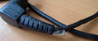
LED strip power supply repair
Many power supplies designed for medium and high power (30 W or more) are built on an integrated driver with a built-in power switch, such as KA5l0365, FSDH065RN, etc. Such solutions are also used in household appliances, for example, in power supplies for DVD players. Such microcircuits are interchangeable; you just need to determine the pinout of the burnt chip and install the one you managed to find.
To repair the power supply for a 12V LED strip (and not only), the circuit remains almost unchanged. You need to make a connection similar to what is shown below. Of course, taking into account the pinout.
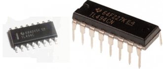
More complex and reliable blocks are built on PWM controllers:
- TL494;
- KIA494AP;
- MB3759;
- KA7500;
They are similar, below is a power supply diagram for an LED strip using them:
The PWM controller is located at the bottom of the circuit; adjustment is made using P1 (on the right in the diagram). By selecting its value, you can achieve the desired output voltage, somewhat similar to adjusting the 431 stabilizer.
Even if your unit does not have a potentiometer or trimmer, you can install it yourself by replacing the constant one, similar to the diagram I provided.
When repairing, look at the signal at the PWM output, power switches T12 and T13 connected to pins 8 and 11 of the TL494.
The picture below shows the adjustment more clearly; the potentiometer is connected to pin 1 of the IC.
Thus, you can experimentally make power for an LED strip with your own hands from any power supply on a 494 PWM controller.
Almost all power supplies can be reconfigured with your own hands within narrow limits to the required supply voltage for the LED strip. At the same time, you will get by with minimal costs.
Please rate the article. We tried our best:)
Did you like the article? Tell us about her! You will help us a lot :)
Basic ways to downgrade
For example, a “running” transformer with a frequency of 50 Hz with a relatively low power of 200 W, made on transformer hardware, weighs more than 1 kilogram and costs from $9–18. This not only makes the power supply bulky, but also significantly increases the cost of the device.
The transformers implement a classic scheme for reducing and then converting alternating voltage (AC) to direct voltage (DC) along the “transformer → rectifier → stabilizer” circuit.
There is a more complex scheme for constructing a “rectifier → pulse generator → transformer → rectifier → stabilizer” switching power supply, which has smaller dimensions.
Calculation of parameters
To prevent breakdown of parts of transformerless circuits, they must be correctly calculated. Each device has its own method.
The transistor unit is calculated according to Ohm's law: U=I×R. It is necessary to calculate the resistances R1, R2, R3 based on the value, voltage and current that each zener diode can withstand.
Calculation of the ballast capacitor for blocks with an RC circuit is carried out using the following formula C = I eff/2*3.14*f *√(Up²-Uв²), where:
- C - ballast capacity (farad);
- Up and Uв — supply and output voltages (volts);
- I eff—load current;
- f is the signal frequency at the device input (hertz).
Since 1 farad = 1 million microfarads, the formula can be simplified:
Resistance R1 (kOhm) is approximately equal to 0.025 of the value of the ballast capacitor. Its power should not be lower than 1 W (optimally 2-5 W).
If manual calculation is inconvenient, find and use an online calculator.
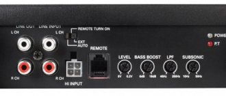
What can 12 or 24 volt voltage be used for in everyday life?
In domestic environments, low voltage power supplies are often used. Portable/stationary electrical and electronic devices, as well as some lighting devices, are powered from 12 or 24V DC voltage:
- cordless electric drills, screwdrivers and electric saws;
- stationary pumps for watering gardens;
- audio-video equipment and radio-electronic equipment;
- video surveillance and alarm systems;
- battery-powered radios and players;
- laptops (netbooks) and tablets;
- halogen and LED lamps, LED strips;
- portable ultraviolet irradiators and portable medical equipment;
- soldering stations and electric soldering irons;
- chargers for mobile phones and power banks;
- low-current power supply networks in places with high humidity and landscape lighting systems;
- children's toys, Christmas tree garlands, aquarium pumps;
- various homemade radio-electronic devices, including those based on the popular Arduino platform.
Most devices run on batteries and Li-ion batteries, but the use of commodity items is not always justified in terms of operating costs. Batteries can be charged 300–1500 times, but galvanic cells with high energy capacity and low self-discharge current are expensive. It will be noticeably cheaper to purchase batteries, especially salt and alkaline ones, but such elements will have to be changed frequently. Moreover, to provide a supply voltage of 12 V, you will need 8 series-connected AA or AAA batteries or 1.5-volt “tablets” in a 27A housing.
Therefore, in places with access to a 220 V 50 Hz household network, it is more rational to use a power supply to power electrical receivers with an amperage of more than 0.1 A.
Capacitor Specifications
For a transformerless power supply, a capacitor designed for the amplitude (or greater) value of alternating voltage is suitable. If the effective voltage value is 220 V, then the amplitude value is calculated using the formula 220 * = 311 V (nominal 400 V). It is better to choose film capacitors; capacitive elements of the K73-17 series are optimal.
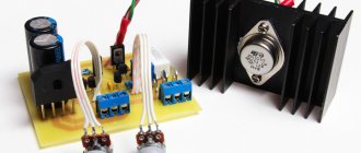
Working diagrams
All described devices are made using common radioelements. Below are diagrams indicating all the parts.
In a power supply with transistor stabilizers, the KT940A can be replaced with a high-voltage one that can withstand more than 250 V, and the KT815G with another one with a minimum voltage of 80 V. With the specified details, the device can output up to 300 mA. To increase the current, transistors must be installed on radiators. If you install D814D instead of the KS512A zener diode, the output current of the device will decrease to 200 mA.