In amateur radio practice there is often a need to use a sinusoidal oscillation generator. You can find a wide variety of applications for it. Let's look at how to create a sinusoidal signal generator on a Wien bridge with a stable amplitude and frequency.
The article describes the development of a sinusoidal signal generator circuit. You can also generate the desired frequency programmatically: Audacity program as a simple sound and noise generator
The most convenient, from the point of view of assembly and adjustment, version of a sinusoidal signal generator is a generator built on a Wien bridge, using a modern Operational Amplifier (OP-Amp).
Bridge of Wine
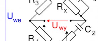
The Wien bridge itself is a bandpass filter consisting of two RC filters. It emphasizes the central frequency and suppresses other frequencies.
The bridge was invented by Max Wien back in 1891. On a schematic diagram, the Wien bridge itself is usually depicted as follows:
Picture borrowed from Wikipedia
The Wien bridge has a ratio of output voltage to input voltage b=1/3 . This is an important point, because this coefficient determines the conditions for stable generation. But more on that later
How to calculate frequency
Autogenerators and inductance meters are often built on the Wien Bridge. In order not to complicate your life, you usually use R1=R2=R and C1=C2=C . Thanks to this, the formula can be simplified. The fundamental frequency of the bridge is calculated from the ratio:
f=1/2πRC
Almost any filter can be thought of as a frequency-dependent voltage divider. Therefore, when choosing the values of the resistor and capacitor, it is desirable that at the resonant frequency the complex resistance of the capacitor (Z) is equal to, or at least of the same order of magnitude as, the resistance of the resistor.
Zc=1/ωC=1/2πνC
where ω (omega) is the cyclic frequency, ν (nu) is the linear frequency, ω=2πν
Wien bridge and operational amplifier
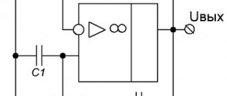
The Wien bridge itself is not a signal generator. For generation to occur, it must be placed in the positive feedback circuit of the operational amplifier. Such a self-oscillator can also be built using a transistor. But using an op-amp will clearly simplify life and give better performance.
Options
- current gain = output current / input current;
- voltage gain = output voltage / input voltage;
- Power gain = output power / input power.
For some devices, such as operational amplifiers, the value of this coefficient is very large, but working with too large (as well as too small) numbers in calculations is inconvenient, so gains are often expressed in logarithmic units.
The following formulas are used for this:
- power gain in logarithmic units = 10 * decimal logarithm of the desired power gain;
- current gain in logarithmic units = 20 * decimal logarithm of the desired current gain;
- voltage gain in logarithmic units = 20 * decimal logarithm of the desired voltage gain;
- signal distortion factor.
The coefficients calculated in this way are measured in decibels. The abbreviated name is dB.
Types of power:
- Nominal.
- Passport noise.
- Maximum short-term.
- Maximum long-term.
Gain factor of three
The Wien bridge has a transmittance b=1/3 . Therefore, the condition for generation is that the op-amp must provide a gain of three. In this case, the product of the transmission coefficients of the Wien bridge and the gain of the op-amp will give 1. And stable generation of the given frequency will occur.
If the world were ideal, then by setting the required gain with resistors in the negative feedback circuit, we would get a ready-made generator.
This is a non-inverting amplifier and its gain is determined by the ratio: K=1+R2/R1
But alas, the world is not ideal. ... In practice, it turns out that to start generation it is necessary that at the very initial moment the coefficient. the gain was slightly more than 3, and then for stable generation it was maintained at 3.
If the gain is less than 3, the generator will stall; if it is more, then the signal, upon reaching the supply voltage, will begin to distort and saturation will occur.
When saturated, the output will maintain a voltage close to one of the supply voltages. And random chaotic switching between supply voltages will occur.
Therefore, when building a generator on a Wien bridge, they resort to using a nonlinear element in the negative feedback circuit that regulates the gain. In this case, the generator will balance itself and maintain generation at the same level.
Phantom power supply
A phantom power source was required to connect the condenser microphone to the camera. Immediately the question is: WHY? Because the camera records sound much better than the computer’s built-in sound card, and it simply already had a condenser microphone. Almost all budget external sound cards still require additional phantom power. And those that do not require are beyond my budget. So I decided to try ordering such a source.
When connecting the microphone through it to the camera, there are no problems, everything works fine, everything is clear, it is recorded. However, the first thing I decided to do was take apart this interesting box. The case is interesting because you can buy it separately for your radio-electronic needs. Another issue is the price, it is not very cheap. Up to three printed circuit boards can be placed inside such a housing. A wonderful thing, if not for the price).
Phantom power supply
Inside the phantom power supply there is a scarf made of budget-friendly PCB, and the board itself is also soldered in a very budget-friendly manner. However, no interference is observed at the output during operation, at least such interference that I could measure with my multimeter. The output voltage is +47V instead of +48, I don’t think this is so critical. In any case, everything works as expected.
We see a bunch of electrolytic capacitors from an unknown Chinese manufacturer. In any case, I don’t know such a manufacturer, but in my work I come across capacitor manufacturers very often. Speaking of the transistor and why it is not attached to either the radiator or the case. I let the scarf work for half an hour, controlling the temperature of the transistor. So it almost didn’t heat up. In a closed case the situation will be more severe, but I think its temperature will definitely not even come close to the maximum permissible.
Microphone phantom power.
By the way, it is worth noting that the power supply of this device is transformer, 18V, 600mA. If anyone is too lazy to read, then everything is the same in the video and in addition you can evaluate the quality of recording through this phantom power supply. I compared the recording quality when recording through the power supply and through the built-in microphone of the camera.
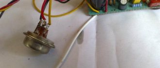
Amplitude stabilization on an incandescent lamp
In the most classic version of the generator on the Wien bridge at the op-amp, a miniature low-voltage incandescent lamp is used, which is installed instead of a resistor.
When such a generator is turned on, at the first moment, the lamp spiral is cold and its resistance is low. This helps to start the generator (K>3). Then, as it heats up, the resistance of the spiral increases and the gain decreases until it reaches equilibrium (K=3).
The positive feedback circuit in which the Wien bridge was placed remains unchanged. The general circuit diagram of the generator is as follows:
Positive feedback elements of the op amp determine the generation frequency. And the elements of negative feedback are reinforcement.
The idea of using a light bulb as a control element is very interesting and is still used today. But, alas, the light bulb has a number of disadvantages:
- selection of a light bulb and a current-limiting resistor R* is required.
- With regular use of the generator, the life of the light bulb is usually limited to several months
- The control properties of the light bulb depend on the temperature in the room.
Another interesting option is to use a directly heated thermistor. Essentially, the idea is the same, but instead of a light bulb filament, a thermistor is used. The problem is that you first need to find it and again select it and current-limiting resistors.
Amplitude stabilization on LEDs
VD1 and VD2 in the negative feedback circuit .
The main gain is set by resistors R3 and R4 . The remaining elements ( R5 , R6 and LEDs) regulate the gain in a small range, maintaining the generation stable. Resistor R5 can be used to regulate the output voltage in the range of approximately 5-10 volts.
It is advisable to use low-resistance resistors ( R5 and R6 ) in the additional OS circuit. This will allow significant current (up to 5mA) to pass through the LEDs and they will be in optimal mode. They will even glow a little
In the diagram shown above, the Wien bridge elements are designed to generate at a frequency of 400 Hz, however they can be easily recalculated for any other frequency using the formulas presented at the beginning of the article.
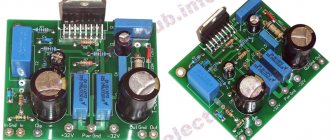
The more power, the worse...
Radio amateurs often try to make their amplifier as powerful as possible (like, it’s cooler), and audiophiles often equip their systems with amplifiers with a power many times greater than that required to sound an ordinary room to a normal volume level, citing the fact that this results in a larger dynamic range. Such amplifiers (high power) sometimes solve some problems, but create others.
The inductance of the power conductors is the main “weak link” of class AB power amplifiers. In such amplifiers, the output transistors are turned on and off alternately, respectively, half-waves of charging currents flow along the positive and negative power buses.
If these pulses enter the audio path through capacitive and inductive couplings, this results in a terrible blurry sound.
This happens if some sensitive track (conductor) passes next to the power bus. Bifilar laying of power wires effectively suppresses radiated interference due to mutual compensation of positive and negative half-waves.
On a printed circuit board, this method can be implemented if the power buses are placed one above the other on both sides of the board (a double-sided printed circuit board is required)
A worthy example of designing a printed circuit board for a power amplifier is the Ultra-LD 200W design, presented in one of the issues of the magazine “Practical Electronics Every Day”. The printed circuit board of this amplifier implements all the installation recommendations presented in this series of articles. And largely due to this, it was possible to obtain a noise level of -122 dB and a level of nonlinear distortion below 0.001%.
Note from the editors of RadioGazeta: if our readers are interested, write in the comments and we will publish a description of this amplifier.
Grounding one side of the PCB works well in high frequency and low current designs. This is not suitable for power amplifiers because it is difficult to predict the flow of currents depending on the choice of ground points.
In modern tube amplifiers, the common bus is often made in the form of a piece of thick tinned wire. Many gurus preach star wiring with a single connection point. There are cases when amplifiers perform poorly with this approach. This is due to the large number of long wires that reduce the stability of the structure.
Typically, a good amplifier will have several ground points.
Quality of generation and elements used
It is important that the operational amplifier can provide the current necessary for generation and have sufficient frequency bandwidth. Using the popular TL062 and TL072 as op amps gave very sad results at a generation frequency of 100 kHz. The signal shape could hardly be called a sinusoidal; it was more like a triangular signal. Using TDA 2320 gave even worse results.
But the NE5532 showed its excellent side, producing an output signal very similar to a sinusoidal one. LM833 also coped with the task perfectly. So it is NE5532 and LM833 that are recommended for use as affordable and common high-quality op-amps. Although, with a decrease in frequency, the rest of the op-amps will feel much better.
The accuracy of the generation frequency directly depends on the accuracy of the elements of the frequency-dependent circuit. And in this case, it is important not only that the value of the element corresponds to the inscription on it. More precise parts have better stability of values with temperature changes.
In the author's version, a resistor of type C2-13 ±0.5% and mica capacitors with an accuracy of ±2% were used. The use of resistors of this type is due to the low dependence of their resistance on temperature. Mica capacitors also have little dependence on temperature and have a low TKE.
Cons of LEDs
It's worth focusing on LEDs separately. Their use in a sine generator circuit is caused by the magnitude of the voltage drop, which usually lies in the range of 1.2-1.5 volts. This allows you to obtain a fairly high output voltage.
After implementing the circuit on a breadboard, it turned out that due to the variation in LED parameters, the fronts of the sine wave at the generator output are not symmetrical. It's a little noticeable even in the above photo. In addition, there were slight distortions in the shape of the generated sine, caused by the insufficient operating speed of the LEDs for a generation frequency of 100 kHz.
Transistor ULF
Transistor low-frequency power amplifiers (UMPA) for sound and audio equipment. The section contains schematic diagrams of homemade low-frequency power amplifiers using bipolar and field-effect transistors.
Here you will find circuits of transistor amplifiers of varying complexity and with different power classes:
- low power - up to 1.5 Watt;
- average power - from 1.5 Watt to 20 Watt;
- high power - 25 Watt, 50 Watt, 100 Watt, 200 Watt, 300 Watt and more.
For a homemade audio complex or when repairing a music center, you can make a multi-channel power amplifier in the following configurations:
- 2.1 system (subwoofer + 2 satellites);
- 5.1 system (subwoofer + 5 satellites);
- stereo - two amplification channels;
- quad - four amplification channels.
Using transistors, you can easily assemble a small homemade headphone amplifier. There are very simple and affordable amplifier designs that are perfect for manufacturing by beginning radio amateurs.
LF amplifier with double thermal stabilization (LME49860, 2SD2394, 2SB1565)
The circuit of a homemade low-frequency power amplifier with double thermal stabilization is made on the LME49860 microcircuit and transistors 2SD2394, 2SB1565 at the output. In my practice, there have been cases when ULF output transistors with temperature protection only overheated and burned out. We had to add thermal protection for current as well. Here is a double protection scheme...
2 2532 0
Economical UMZCH on transistors 2SC3331V, 2SA1286, 2SA928A, 2SD2058Y (13W)
When repairing modern low-frequency power amplifiers assembled using integrated circuits, it is not always possible to purchase the required microcircuits or find suitable ones in amateur radio bins. In this case, instead of a faulty microcircuit, you can make an easy-to-assemble one...
2 3620 0
UMZCH circuit with five transistors and unipolar power supply (60W)
Usually, if you need to make an UMZCH quickly and without unnecessary parts, radio amateurs pay attention to microcircuits - integrated UMZCHs. Indeed, a positive result immediately with a minimum of parts and assembly time. However, UMZCH can be done quickly and relatively “without unnecessary details”...
1 7204 0
A simple AF amplifier with three transistors, circuit (KT3102, KT816, KT817)
The amplifier is built according to a simple circuit with three transistors. At the output, at a load with a resistance of 4 Ohms, it produces 2W power when powered by a 12V source. The input impedance of the amplifier is low, 470 Ohms. Such a low input impedance allows it to match well...
4 11084 16
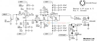
Hybrid UMZCH based on ECC88, 6N23P lamps and LM3875 microcircuits (30W)
Circuit diagram of a homemade hybrid audio amplifier using tubes and microcircuits with an output power of 30 Watts. The amplifier is built on an ECC88 lamp (domestic analogue - 6N23P) and a powerful LM3875 microcircuit.
3 4000 7
Circuit of a powerful guitar amplifier using transistors TIP142 and TIP147 (60W)
Schematic diagram of a guitar low-frequency power amplifier with a preamplifier and tone control. The UMZCH is assembled on TIP142 and TIP147 transistors, output power is 40 W at 8 Ohms, 60 W at 4 Ohms.
3 4574 2
Simple high-quality low-frequency power amplifiers based on MOS transistors
Several schematic diagrams of high-quality UMZCHs based on field-effect transistors, attractive with their simplicity and technical characteristics. The use of field-effect transistors in a power amplifier can significantly improve sound quality while simplifying the overall circuit...
6 10038 1
Stereo audio amplifier using MOSFET transistors (200W)
The electrical circuit diagram of the amplifier is shown in the figure (replaced elements are shown in parentheses). This design is a modernization of the development [1]. Schematic diagram of UMZCH on MOSFET transistors (200W). All the main parts of the amplifier - transformer, radiators...
7 7397 1
Audio power amplifier with stabilized power supply (200W at 4 Ohm)
When developing AF amplifiers with a maximum output power of more than 100 W, the need to obtain the highest possible amplifier efficiency with sufficiently low nonlinear distortions becomes paramount. The issue of the permissible percentage of nonlinear distortion of an AF amplifier has been discussed more than once at...
4 7439 0
Several transistor UMZCH circuits, chronology of a radio amateur
I began my acquaintance with powerful amplifiers in 1958, when I was studying at the Power Engineering College, and I was assigned to service a radio center. It consisted of three parts: a small-sized radio broadcasting installation “TU-100”, a tape recorder “Dnepr 9” and a LATR on ...
3 10227 0
1 …
4148 diodes instead of LEDs
The LEDs have been replaced with the beloved 4148 diodes. These are affordable, high-speed signal diodes with switching speeds of less than 4 ns. At the same time, the circuit remained fully operational, not a trace remained of the problems described above, and the sinusoid acquired an ideal appearance.
In the following diagram, the elements of the wine bridge are designed for a generation frequency of 100 kHz. Also, the variable resistor R5 was replaced with constant ones, but more on that later.
Unlike LEDs, the voltage drop across the pn junction of conventional diodes is 0.6÷0.7 V, so the output voltage of the generator was about 2.5 V. To increase the output voltage, it is possible to connect several diodes in series, instead of one, for example like this:
However, increasing the number of nonlinear elements will make the generator more dependent on external temperature. For this reason, it was decided to abandon this approach and use one diode at a time.
Will need
Power transistors and operational amplifier:
- 2SC5200 Transistors x 5 - https://ali.pub/4xjey2
- 2SA1943 Transistors x 5 - https://ali.pub/4xjf1k
- Op-amp HA17741 x 1 - https://ali.pub/4xjf4h
Other components: Show/Hide text
- SC 2SC2073 Transistors x 2.
- S 2SA940 Transistors x 2.
- 3 0.33/5 W resistors x 10.
- 4.7/1W resistors x 10.
- resistors 10/2 W x 2.
- resistors 100/1 W x 6.
- resistors 330/1 W x 2.
- 10 resistors x 1.
- 100 resistors x 1.
- 1K resistors x 1.
- 5K6 resistors x 2.
- resistors 10K x 2.
- 47K resistors x 1.
- resistors 100K x 1.
- 33P capacitors x 1.
- capacitors 220P x 4.
- 680P capacitors x 1.
- 0.1 uF capacitors x 1.
- 10uF/50V capacitors x 2.
- 100uF/25V capacitors x 3.
- 10,000 µF / 80 V capacitors x 2 or x 4.
- Diode 4148 x 2.
- Diode bridge 35A X 1.
- Zener diode 15V X 2.
- Coil 16 turns (copper wire with a diameter of 1.5 mm).
- 50K Potentiometers x 1.
- Mica insulation of transistors x 10.
- Aluminum radiator x 1.
- Transformer 45 - 50 VAC 2 x 30A.
We recommend reading: Stabilizer AMS1117-3
Replacing a variable resistor with a constant one
Now about the tuning resistor. Initially, a 470 Ohm multi-turn trimmer resistor was used as resistor R5. It made it possible to precisely regulate the output voltage.
The use of a variable resistor in such circuits is undesirable for two main reasons:
- unreliability of the moving contact
- the presence of parasitic inductance in multi-turn trimmers, which can adversely affect the quality of the output signal
When building any generator, it is highly desirable to have an oscilloscope. Variable resistor R5 directly affects generation - both amplitude and stability.
For the presented circuit, generation is stable only in a small resistance range of this resistor. If the resistance ratio is greater than required, clipping begins, i.e. the sine wave will be clipped from above and below. If it is less, the shape of the sinusoid begins to distort, and with a further decrease, the generation stalls.
It also depends on the supply voltage used. The described circuit was originally assembled using an LM833 op-amp with a ±9V power supply. Then, without changing the circuit, the op amps were replaced with AD8616, and the supply voltage was changed to ±2.5V (the maximum for these op amps). As a result of this replacement, the sinusoid at the output was cut off. The selection of resistors gave values of 210 and 165 ohms, instead of 150 and 330, respectively.
How to choose resistors “by eye”
In principle, you can leave the tuning resistor. It all depends on the required accuracy and the generated frequency of the sinusoidal signal.
To make your own selection, you should first of all install a tuning resistor with a nominal value of 200-500 Ohms. By feeding the generator output signal to the oscilloscope and rotating the trimming resistor, reach the moment when the limitation begins.
Then, by lowering the amplitude, find the position in which the shape of the sinusoid will be the best. Now you can remove the trimmer, measure the resulting resistance values and solder the values as close as possible.
If you need a sinusoidal audio signal generator, you can do without an oscilloscope. To do this, again, it is better to reach the moment when the signal, by ear, begins to be distorted due to clipping, and then reduce the amplitude. You should turn it down until the distortion disappears, and then a little more. This is necessary because It is not always possible to detect distortions of even 10% by ear.
Additional reinforcement
The sine generator was assembled on a dual op-amp, and half of the microcircuit remained hanging in the air. Therefore, it is logical to use it under an adjustable voltage amplifier. This made it possible to move a variable resistor from the additional generator feedback circuit to the voltage amplifier stage to regulate the output voltage.
The use of an additional amplifier stage guarantees better matching of the generator output with the load. It was built according to the classical non-inverting amplifier circuit.
The indicated ratings allow you to change the gain from 2 to 5. If necessary, the ratings can be recalculated for the required task. The cascade gain is given by the relation:
K=1+R2/R1
Resistor R1 is the sum of variable and constant resistors connected in series. A constant resistor is needed so that at the minimum position of the variable resistor knob the gain does not go to infinity.
Microphone amplifier circuit on a chip
There are many microphone amplifier designs on a chip. Most often, devices use operational amplifiers, but there are integrated components that represent a ready-made microphone channel. An example of such a design is the specialized low-noise microphone amplifier microcircuit MAX9814. It has the following parameters:
- Programmable gain – 40, 50 and 60 dB
- Harmonic distortion – 0.04%
- Built-in power supply for electret micro – 2V
- Temperature range – +80- –400С
- Has automatic gain control
For independent repetition, circuits based on integrated op-amps are suitable.
The circuit is assembled on the domestic OU 157UD2. This is a microcircuit with a very low noise level that is not critical to the supply voltage.
The high-quality channel is designed to work with all types of electret microphones. It uses a BA4558 or JRS4558 op-amp. Capacitors C1 and C4 are 0.22 µF each. The circuit is highly sensitive. Does not require adjustment and starts working immediately after supply voltage is applied. The following device uses the K538UN3B microphone chip.
It is very simple, since it does not contain resistors and its assembly requires only a microcircuit and four capacitors. The supply voltage can be reduced to 3 volts without large gain losses. When repeating designs, you need to connect the microphone amplifier with a shielded wire and connect the screen to the device body.
How to strengthen the output
The generator was intended to operate at a low-resistance load of several ohms. Of course, not a single low-power op-amp can produce the required current.
To increase power, a TDA2030 repeater was placed at the generator output. All the goodies of such an application of this microcircuit are described in the article Voltage repeater circuit on an op-amp. Powerful voltage repeater on TDA2030.
And this is what the circuit of the entire sinusoidal generator with a voltage amplifier and a repeater at the output looks like:
The sine generator on the Wien bridge can also be assembled on the TDA2030 itself as an op-amp. It all depends on the required accuracy and the selected generation frequency.
If there are no special requirements for the quality of generation and the required frequency does not exceed 80-100 kHz, but it is supposed to work with a low-impedance load, then this option is ideal for you.
Result
Previously, something went wrong with my distortion measurements. Much later, when I got a HiRes DAC-ADC, I tried it again. It didn’t turn out that bad, but as a source for measuring Kg in audio, this circuit is clearly not suitable. The sine wave circuit produces, of course, a beautiful one.
| Wien Bridge + LM324 + CCS: signal output |
Measurement results: THD 1.5%,
2nd harmonic -36dB, 3rd -64dB, 4th -89dB.
Two generators coexisted on one breadboard - a sinusoidal and a sawtooth signal:
| TLC555CP + LM324 = two generators |