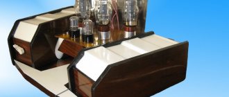
Scheme of three-way tube UMZCH G. Mudretsov on 6N1P, 6P14P
G. Mudretsov (MRB-1974) preceded his scheme for a three-band high-quality UMZCH with lengthy discussions about the need to divide frequencies into channels. In some amplifiers, this separation is carried out at the output: the amplifier amplifies the entire frequency band, and the signal is divided into two bands only by loudspeakers. In other amplifiers, the separation occurs at the input or before the final stage.
When the amplification is divided into several bands, lower frequencies are amplified by one amplification channel, higher frequencies by another. In this case, even with nonlinear distortions, the most harmful combination frequencies will not arise at the output of each channel.
When the frequencies at the amplifier output are separated, only the combination frequencies occurring in the loudspeakers are reduced, while the distortion created by the amplifier remains completely intact. Therefore, dividing the frequency range at the amplifier input gives higher sound quality, since the combination frequencies that arise not only in the loudspeaker, but also in the amplifier, are reduced. However, one should not think that the use of separated loudspeakers with single-side amplification is ineffective. First of all, the range of reproduced frequencies is significantly expanded. If it is not difficult to build an amplifier for a wide frequency range, for example, 40...10000 Hz, then it is impossible to reproduce such a frequency band with one loudspeaker.
Using multiple speakers reduces distortion caused by the Doppler effect. When one loudspeaker reproduces simultaneously low and high frequencies of a signal, the diffuser oscillates slowly with large amplitude at lower frequencies and at the same time makes rapid oscillations with low amplitude at higher frequencies. High-frequency sound turns out to be modulated by low-frequency sound. Such frequency modulation is perceived by ear as nonlinear distortion.
Multi-band audio reproduction systems effectively reduce the most harmful types of distortion - combination frequencies and frequency modulation from the Doppler effect in loudspeakers.
With three-way amplification, there is no need for a special tone control; The frequency response is adjusted over a wide range by a conventional gain control at the input of the low-frequency and high-frequency channels. The absence of a separate tone control significantly simplifies the circuit. Compared to a two-way amplifier, in which both channels have the same power and the same high quality of reproduction, a three-way amplifier adds only two stages of the high-frequency channel. High quality playback, ease of adjustment with little complexity - these are the advantages of a three-way amplifier.
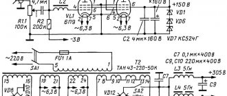
The schematic diagram of a three-way amplifier is shown in Fig. 53. The first amplification stage, made on the left (according to the diagram) half of the L1 lamp, is 6schk for all three channels; it amplifies the entire frequency band. After it, the range of amplified frequencies is divided into three bands. The frequency of separation of the channels of low and medium frequencies is 300 Hz, medium and high - 2500 Hz. At these crossover frequencies, each channel has the same frequency bandwidth (on the logarithmic scale of the frequency scale).
In the channel of higher audio frequencies (lamps L2 and L3), to attenuate low and medium frequencies, transition capacitors C1 and C3, as well as a capacitor in the bias circuit of the first stage C2, have a capacitance significantly less than the usual value. The final and pre-final stages are covered by negative feedback, the voltage of which is supplied to the cathode circuit of the second stage.
The mid-frequency channel has two voltage amplification stages, made on the right half of lamp L1 and lamp L4, and a push-pull final stage on lamps L5 and L6. The frequency division circuit has the most difficult task here: it needs to attenuate the low and high frequencies while providing good midrange boost. Attenuation of lower frequencies is achieved by reducing the capacitance of transition capacitors C11 and C14 and the bias capacitor C13, i.e. by the same means as in the higher frequency channel, but the capacitor capacitance is larger here. Attenuation of higher frequencies is achieved due to the shunting action of capacitors C12 and C15. The phase inversion stage is made according to a circuit with a grounded grid on the right half of the L4 lamp. This circuit has good symmetry and is convenient for introducing feedback. The feedback voltage is supplied to the grid of the right triode of lamp L4.
It may seem that with such a circuit the feedback will act only on the right triode of lamp L4. However, it is not. The right and left triodes of the L4 lamp are connected completely symmetrically. A direct signal is applied to the left triode grid; due to the coupling resistance between the stages, it also acts on the grid of the right triode. The depth of feedback depends on the ratio of the resistance values R22 and R24. Capacitor C20 prevents the occurrence of high-frequency generation. To raise lower and higher frequencies, the gain of the mid-frequency channel is reduced several times by the voltage divider R14, R15. The greater the attenuation of this divider, the higher the relative rise in frequency response in the region of higher and lower frequencies can be.
| Designation on the diagram | Number of turns | Wire brand and diameter, mm | Core | |
| Tr1 | ||||
| I | 1500 | PEL | 0.14 | Ш-12х12 |
| II | 41 | PEL | 0,74 | |
| TR2 | ||||
| I | 1000x2 | PEL | 0.14 | Ш-16х24 |
| II | 40+5 | PEL | 0,74 | |
| TR3 | ||||
| I | 1500x2 | PEL | 0.14 | Ш-20х30 |
| I | 45+45 | PEL | 0,74 | |
| Tr4 | ||||
| I | 286 | PEL | 0,68 | Ш-25х64 |
| II | 44 | PEL | 0,68 | |
| III | 285 | PEL | 0,68 | |
| IV | 44 | PEL | 0.68 | |
| V | 600 | PEL | 0,41 | |
| VI | 18 | PEL | 2,1 | |
| Dr1 | 1200 | PEL | 0,34 | Ш-16х 24 |
The low-frequency channel is made according to a similar circuit, with the exception of the frequency division circuit. To attenuate the higher and middle frequencies, negative feedback is introduced in the first stage of the channel (lamp L7a), the voltage of which is supplied from the anode to the grid of the lamp L7a through capacitors C23, C24, C22. In addition, the input of the second stage (lamp L8a) is bypassed by capacitor C28.
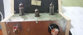
The rectifier (Fig. 54) has a filter for the final stages of low and medium frequencies and all other amplification stages.
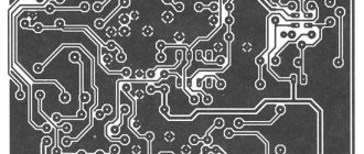
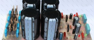
The amplifier parts are located on circuit boards (Fig. 55). Data for transformers and chokes are given in the table.
Source: Radioamator 1999. 40 best designs of tube UMZCHs over 40 years.
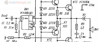
A simple DIY audio amplifier circuit
When creating a homemade device, a radio amateur has to solve many different problems. One of them is related to the output power, which is limited by the supply voltage. First of all, this applies to car systems, since they receive power from the on-board network. An exemplary option would be to use individual microcircuits. The circuit of a complete audio amplifier is a pre-stage with effective tone controls and a final block. The proposed design contains the following characteristics:
- Output power – 20 WX 2
- Frequency band – 40 – 18,000 Hz
- Distortion factor – 1.0%
- Supply voltage – 8-18 V
Sound amplifier for speakers printed circuit board diagram A powerful amplifier on a microcircuit assembled with your own hands can be used at home or installed in a car.
The simplest audio amplifier circuit
The simplest device consists of an integrated circuit and two capacitors. One of them is separating, and the second works as a power filter. The device does not require adjustment and, if assembled correctly, starts working immediately after switching on. The audio amplifier connection circuit allows power from a car battery.
The terminal circuit is made on a TDA7294 chip. The rated power delivered to a 4 ohm load is 70 watts, and the maximum is 100 watts. The chip is used for wideband speaker systems or a subwoofer. To obtain such power, you will need a bipolar power supply with a voltage of 35 volts.
Audio amplifier for speakers circuit board circuit
The printed circuit board for this circuit is made of foil-coated PCB by etching. The pattern of printed tracks can be applied with asphalt-bitumen varnish or other composition. The easiest way to etch a board is in a ferric chloride solution. In order for the audio amplifier on a microcircuit, made by yourself, to work stably, we install the TDA1552Q element on the radiator. To obtain good sound and minimal distortion, capacitors C11, 12, 13 and 14 must be film. Resistors R7 and R8 set the maximum undistorted signal on the speaker systems.
Audio amplifier circuit
Integrated circuits are gradually replacing transistors from low-frequency amplifier circuits. TDA2005-2052 devices have become widespread. They provide sufficient output power to provide sound for a car interior or living room. A simple DIY stereo audio amplifier can be assembled on a single TDA2005 chip.
It is better to use film capacitors C8 and C12. If the supply voltage does not exceed 12 V, then all electrolytic capacitors must be 16 V. With a higher supply voltage, the operating voltage of the capacitors must be increased. A self-assembled amplifier is used for speakers with a resistance of 2 to 4 ohms.
Simple DIY sound amplifier
You can assemble an audio amplifier with your own hands without microcircuits using any transistors, including both bipolar and field-effect ones. The use of field-effect transistors in the output stage made it possible to create a device whose characteristics are close to those of tube designs.
The scheme has the following characteristics:
- The frequency response is linear in the range 20 Hz-100 kHz
- Distortion rate at 1 kHz does not exceed 0.003%
- Output power 10 watts into 8 ohm load
To drive the output stage, a voltage of 0.7 volts is required, which must be provided by the preliminary stage. The NE5534 operational amplifier can be replaced with the domestic op-amp KR140UD608. Zener diodes must be designed for a stabilization voltage of 18 volts. The 1N4705 can be replaced by two semiconductors in series, 9 volts each.
ACTIVE CROSSOVER FOR THREE-WAY HI-FI AUDIO SYSTEM
Audio crossovers, or crossover filters in Russian, are devices in sound systems that create the desired operating frequency ranges for dynamic heads that are designed to operate in a specific frequency range. They do not accept frequencies outside these limits. If a low frequency is applied to the high-frequency speaker (tweeter), the sound picture will be distorted. High-frequency speakers should only handle high frequencies, and woofers should only receive the low-frequency range from the overall audio signal. The remaining middle band goes to mid-range speakers (midwoofers). Therefore, the task of crossovers is to divide the audio signal into the required (optimal) frequency bands for the corresponding types of dynamic heads.
Crossovers are divided into passive ones, consisting of only RLC
, and active ones, the filters of which use transistors or operational amplifiers. The most common are two-way with one cut-off frequency and operating on two speakers, and three-way with two cut-off frequencies and, accordingly, with three dynamic heads.
With the help of sensitive and accurate analyzers, it can be determined that the best sound quality can be achieved if the reproduced frequency range is divided into at least three parts, and the resulting bands are amplified and reproduced by separate means. From this “ frequency decomposition
"The terms "
tweeter
" -
high frequency
, "
midwoofer
" - mid-frequency speaker and "
subwoofer
" -
low frequency
.
When comparing passive and active crossovers (crossover filters), the former leads to power loss, and the characteristic curve of the band separation is not curved enough, so the signals of adjacent bands are mixed, which causes distortion, not to mention the special requirements for LC
-elements.
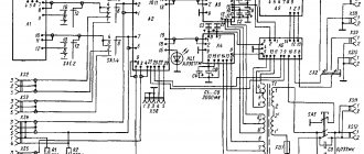
A much better solution is to use active crossovers, where the separation of the bands corresponding to the high, mid and low ranges is realized using high-precision, steep, linear filters with phase shift at a low level, which are then amplified by a stepped output to the corresponding speakers. The diagram of such an active crossover (left channel), which was published in the magazine “Hobby Elektronika” No. 12/2003
, is shown in the figure below.
Generated by frequency response
are shown in the figure below.
The HF
channel with a
frequency
response
24 dB/octave
(cutoff frequency about
5.5 kHz
) is formed
DA2.1-DA2.4
with a variable sensitivity resistor
R33
.
The remaining part of the spectrum is separated by an additional function filter ( AFF
) - in this case,
a low-pass filter DA1.2-DA1.4 (R13, R15, R16)
and fed to
fourth-order high-pass
filter DA3.1-DA3.4
, at the output of which a
midrange
, as well as the second
FDF DA4.1-DA4.3
, at the output of which
a low-frequency
channel is formed.
To obtain good filter performance, it is important to select accurate RC
-elements that determine cutoff frequencies.
It is advisable to use resistors with a tolerance of 1%, and when selecting capacitors (regular K10-17B
), use
C
-meter.
The PCB version for the stereo crossover option is shown in the figure below. Positional designations of components with an apostrophe indicate that it belongs to the right channel. The variable resistors used in the circuit are double ones for mounting on a printed circuit board RK-1233G1
.
Source