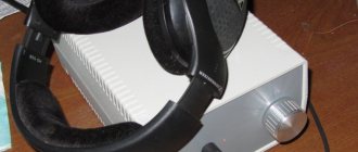
Simple schematic diagrams of homemade converters for receiving radio stations in the VHF bands on receivers in which the required frequency range is not available are presented. The converter is a converter of the frequency of the input signal into a frequency available for reception by existing equipment.
Typically, a homemade simple converter is based on either a transistor circuit or a frequency converter on a K174PS1, K174PS4 microcircuit. Recently, converter circuits based on imported SA602, SA612, NE612 microcircuits began to appear. But other options are quite possible.
In practice, the converter can be based on any microcircuit—a receiver frequency converter capable of operating at the required frequencies.
Here we describe the circuits of two converters based on the LA1185 chip from SANYO. This microcircuit is a frequency converter. It contains an RF amplifier, the input of which is supplied with a signal. Next comes a frequency converter, consisting of a mixer and a local oscillator. As well as a supply voltage stabilizer. The schemes are almost the same, but operate on different ranges.
FM-VHF converter on K174PS1
Almost all Soviet radios and receivers have a VHF range with a frequency range of 64.5-74 MHz. If you listen to this section now, you can conclude that this range is practically “dead”. In some large cities you can still hear one or two stations.
All leading radio broadcasting stations are located on the so-called “FM band”, which is also a VHF band with frequency boundaries of 87.5?108 MHz, and the name “FM” is unofficial and takes its meaning from the type of modulation - frequency modulation.
To transfer an old, Soviet receiver to the FM range, you can make changes in the VHF unit by changing the capacitance and inductance of the local oscillator, mixer, and so on. It will be much easier to assemble the FM-VHF converter, besides, the radio receiver will not be modified and the converter can be disconnected or removed at any time.
I would like to note that the FM-VHF converter presented in this article consumes only 2mA.
FM -VHF converter circuit
The diagram is taken from the magazine Modelist-Constructor No. 10 for 1990, presented by V. Rastorov (Taganrog).
The circuit is not complicated and works perfectly, and if anyone claims that it is unstable and works poorly, then most likely they did not configure it properly.
The converter operates on the basis of the K174PS1 microcircuit, which includes a local oscillator and a mixer. The local oscillator is tuned to a frequency of 23-34 MHz using elements L1, C1, C4, C5.
The signal received by the antenna through the isolation capacitor C2 is supplied to pin 7 of the K174PS1 microcircuit, and then it is mixed with the signal generated by the local oscillator. At pin 2 a mixed difference and sum signal is generated.
Now for an example. When receiving a radio station with a frequency of 103.1 MHz (Iskatel radio in Irkutsk), the signal from the antenna through C2 enters the mixer of the K174PS1 microcircuit, where the frequency of 103.1 MHz (and other frequencies) is mixed with the local oscillator signal. If we tune the local oscillator to a frequency of, for example, 30 MHz, then resistor R3 will have a mixed difference component with a frequency of 73.1 MHz, which will go through the isolation capacitor C6 to our Soviet receiver with a frequency range of 64.5?74 MHz. The total component on resistor R3 will lie at a frequency of 133.1 MHz and will not be received by our receiver.
The presented FM-VHF converter can also work in the opposite direction; by connecting an FM receiver, we can receive VHF stations lying in the range 64.5-74 MHz (the total component of the mixer will be received).
Circuit components
When designing the printed circuit board for the FM-VHF converter, I added two components that were missing from the diagram: a 78L05 stabilizer for the output voltage of +5V and a 330nF capacitor at the input of the stabilizer. This modification allows you to power the converter with DC voltage up to +28V.
An additional seat for capacitor C1 has also been added, this is for extreme measures of adjusting the local oscillator frequency (read below).
The capacitors are all ceramic, I used Chinese ones, the frequency does not drift away from the tuned station during 2 hours of operation. Resistors with a power of 0.25W. As an antenna, a piece of copper wire 20 cm long.
Coil parameters and settings
Most of the tuning depends on the coil parameters. I don’t have a high-frequency generator and a frequency meter, so I did the tuning using radio broadcast stations, which made the procedure much more complicated.
For the coil, 5-7 turns are recommended on a frame with a diameter of 4 mm with a ferrite core (permeability unknown). Wire diameter up to 0.63mm.
I had one ferrite core from a PC power supply inductor, permeability unknown. With 5-7 turns I caught a lot of FM stations, but I couldn’t fit the whole range. The adjustment is made by changing the position of the core in the coil frame.
Next, I tried to make a coil without a rod and frame. Excellent reception of stations at frequencies from 103.5 MHz to 107.5 MHz was on a frameless coil wound on a frame (diameter 5 mm) with copper wire (diameter 0.63 mm) and having 8 turns. When tuning, you need to loosen the coil turns a little and search for stations on the radio.
The most optimal and finishing coil was made on a frame from the oscillating circuit of a foreign receiver. Frame diameter 4mm. Inside the frame there is a tuning core with unknown permeability. The coil contains 6 turns of copper wire with a diameter of 0.63mm. The value of the local oscillatory circuit capacitor C1 was also changed to 630pF. Using a tuning core and changing the capacitance C1, I was able to tune the entire FM range on the VHF receiver.
To understand, in order to increase the local oscillator frequency, the inductance of the coil must be reduced and vice versa.
In any case, 5-7 turns on a frame with a diameter of 4-5mm allows you to easily tune in to several FM stations. And then by changing the distance between the turns or changing the position of the core, fine adjustment is made, which may have to be tinkered with. As a last resort, you can change the capacitance of C1; for this, the board has two seats for this capacitor. For capacitors connected in parallel, the capacitances add up. To increase the frequency of the local oscillator, the capacitance of capacitor C1 must be reduced and vice versa.
Installation in a radio receiver
It is recommended to install the converter closer to the metal part of the case, which is connected to a common wire or ground. I installed the converter board on the radio frame, which is connected to the common wire (in my case, negative).
Also, the FM-VHF converter should be installed as close as possible to the antenna connection socket.
When installing in portable receivers, you need to use a switch along the power line so as not to simply waste battery power. I did not install the switch, since I have a radio, and the power is taken from the +15V power supply line of the tone control unit.
In conclusion, I want to say that almost all stations are received cleanly, even without an antenna.
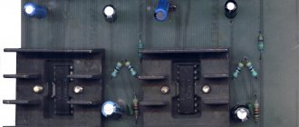
Printed circuit board for FM-VHF converter on K174PS1
FM converter on one transistor
The article describes the simplest VHF converter for receiving radio stations in the “European” range of 88-108 MHz on domestic radios. The design was repeated more than 200 times over several years.
In the converter circuit, the absence of scarce parts, ease of execution, setup without instruments, and stability of the circuit are the main features of the described device. Several years ago, an urgent need arose - to ensure the reception of radio stations in the European part of the VHF range (88-108 MHz). Initially, these stations began to appear in the countries of the former socialist camp, like mushrooms after rain, and then in our country.
At first, a big obstacle to progress was the lack of this range in the Soviet standard, and therefore the lack of mass radio receivers to receive it. A VHF converter came to the rescue. At one time, circuits of varying degrees of complexity were tested - from three transistor to one transistor.
It turned out that in most cases the simplest single transistor option was optimal. It should be noted right away that the diode mixer in most cases was significantly inferior to the transistor frequency converter in terms of frequency transmission (conversion) coefficient and harmonic spectrum.
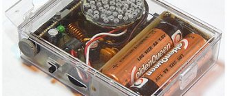
According to the diagram in Fig. More than two hundred (200!) converters were manufactured on the site. Not a single discrete element of the circuit was selected, and deviations in values reached up to 20%. Transistors were installed without checking the gain. The frequency converter is made on transistor VT1 type KT315 with any letter index. All circuits are without cores. The input circuit P and the output circuit L4 are wound with wire PEV-1-0.8. The communication windings L2, L5 and heterodyne circuit 13 are wound with PEV-1-0.18 wire. Number of coil turns: L1 – 6 turns; L2, L5- 2 vit.; L3 – 3+13 vit.; L4 – 7 vit.
First, on a 04 mm mandrel (a drill shank was used), coil L1 is wound turn to turn. The leads are cleaned of enamel, and the coil is soldered into the board. Then the L2 communication coil is wound. The drill is not removed from the reel yet. The end of the wire is cleaned of enamel and soldered into a circuit board. The communication winding is wound between the turns of the loop coil. Then the second end of the communication coil is soldered into the board, and the mandrel drill is removed from the coil. The outer turns of the contour coil are slightly moved apart. Coils L4 and L5 are wound and sealed in the same way.
The local oscillator coil L3 is wound on a plastic rod with a diameter of about 3.5 mm (vinyl rods from snowblower brushes were used). After stripping the insulation of the leads, the coil is soldered into the board. Then the remaining parts are installed. The length of their pins is minimal, so the height of the board is very small.
All capacitors in the circuit may have deviations from the values indicated on the diagram by up to 20%, the resistor - more than 30%. KT315 transistors were used with various letter indices, i.e. with a spread of gain factors over a very wide range. The capacitance of capacitor C6 generally ranged from several thousand pF to 0.1 µF. This did not affect the operation of the converter.
The leads of all elements had a minimum length. The whole setup consisted of choosing a working section of the range, namely a section. For some reason, most article authors avoid this issue. And then their followers wonder why they cannot receive radio stations from the entire VHF range on the converter? The range covered by the original radio receiver is about 1 MHz (65.9-74 MHz [1]).
Without changing the frequency overlap of this radio receiver, but only by transferring its tuning to another section of the VHF band with a converter, naturally, it is possible to ensure reception of only the same frequency band (about 10 MHz). And no more. And the new VHF range, according to the standard, occupies a band of 20 MHz (88-108 MHz), i.e. twice as big. This means that without expanding the reception bandwidth of a standard VHF receiver, especially with a fixed local oscillator setting of the converter, it is impossible to ensure reception of stations of the entire “European” VHF range.
This comes at the cost of the simplicity of the converter circuit. All that remains is to choose the correct tuning frequency for the converter local oscillator so as not to lose at least what is left. Before setting up the converter, the turns of the coils L2 and L4 are slightly moved apart. The output of the converter is connected to the antenna socket of the VHF radio. The converter supply voltage is not critical. The operation of the circuit has been tested when powered from a 5-12 V source, therefore, as a rule, the supply voltage of the main radio receiver circuit is used.
By tuning the main radio receiver, we achieve reception of any radio station in the new VHF range. By slightly moving the turns of the heterodyne circuit L3 of the converter, the received part of the sub-band is shifted. Sometimes, with large deviations in the capacitance of capacitor C4, it may be necessary to reduce the number of turns of L3 by 1-2 turns. Having achieved reception of the required radio station, check the settings of L1 and L4. If, when introducing a metal knitting needle (drill) into these circuits (one by one), the signal of the received station increases, then the turns of these coils must be slightly moved apart.
An increase in the volume of the received radio station when a thin ferrite core is inserted indicates the need to compress the coil turns. And one last thing. It is hardly necessary to select the capacitor of the local oscillator circuit of the C4 converter according to the TKE value. After all, almost all radio receivers to which converters will be connected have and use APCG. Accordingly, fluctuations in the converter supply voltage had virtually no effect on the stability of reception, and no significant effect of shielding of the converter was noticed when it was built into a radio receiver, so shielding was not performed.
Naturally, after minor changes to the circuit, the converter can be used with radios that have a grounded positive power source. To do this, you can go two ways. Change the type of conductivity of the transistor used in the converter or change the connection points of the common terminals of the L2,15 coils. They can now be connected to a common power supply. The converter mass is isolated from the radio body. Well, the simplest solution is to connect the antenna to the converter and the converter itself to the radio receiver through two small capacitors.
The printed circuit board drawing is shown in Fig. 2. In conclusion, I would like to note that the stability of the converter’s operation was primarily influenced by the stability of the parameters of all circuits. Especially in conditions of vibration (on vehicles), so the circuits were wound with a rather thick wire, and after adjusting the circuit they were filled with molten (soldering iron) paraffin. The printed circuit board was covered with several layers of varnish after all elements were soldered and configured.
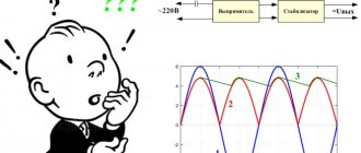
Formulation of the problem
I have already written about frequency stabilization and indication, this is understandable. But there is another important point: receivers with low IF have an intractable problem - the mirror channel. And this problem manifests itself when it is necessary to receive a weak station, next to which there are two strong ones. As a result, we hear a signal from a strong station interfering with the mirror channel.
This can only be effectively combated by increasing the IF, for example to the standard value of 10.7 MHz, and with such an IF a fractional detector should be used. We'll settle it on that. As a result, a receiver with a digital local oscillator, indication and a classic (almost) tube circuit emerges.