Everything has its beginning, and if we are talking about amplifier operating modes, the origins are, of course, class A. It is with this that the history of amplifiers in particular and electronic audio in general began. Everything that came before had nothing to do with electronics, and indeed nothing to do with electricity, and everything that came after is easiest to understand if you know how class A amplifiers work. Well, the most surprising fact: despite the fact that this circuitry has already managed to achieve its centenary, it is still in demand and competes on equal terms with the most advanced circuit solutions of the 21st century.
Principle of operation
Back in 1916, the Swedish scientist Ernst Alexanderson, who worked for the American company General Electric, received a patent for an amplifier circuit, which is known throughout the world as class A. The operating principle of a class A amplifier is extremely simple, and to create an amplifier of this type, one transistor or one lamp is enough . To understand how it works, let's consider a more classic solution: a lamp.
Directly in the process of amplifying the sound signal in a radio tube, three structural elements are involved: anode, cathode and grid. When power is applied to the circuit, a flow of electrons occurs between the cathode and anode, and the grid located between them acts as a control valve.
If there is an electrical potential on the grid, it prevents the free passage of electrons, and the higher the electrical potential on the grid, the fewer electrons pass from the cathode to the anode until the lamp is completely closed. Thus, by connecting the payload (the acoustic system) between the cathode and the anode and applying a signal to the control grid, we get the simplest power amplifier circuit.
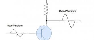
The specificity of an amplifier that works with an audio signal is that the sound wave has a symmetrical shape with positive and negative components equal in amplitude.
When such a signal is applied to the input of the amplifier, the following will happen: at the moment the positive half-wave passes, the lamp will open and close so that the output signal follows the shape of the sound wave at the input. But at the moment when the negative part of the half-wave arrives at the input, the grid will already be completely locked, and instead of playing sound at the output of the amplifier, we will get silence.
Despite the fact that in the article we are talking mainly about class A tubes, transistors are also capable of operating accordingly, and in the picture above you can see a standard circuit
In order to give the tube the ability to reproduce both halves of the signal, Ernst Alexanderson arranged for the zero point of the incoming signal to be shifted relative to the zero point (fully closed state) of the tube to approximately the middle of its operating range. Thus, the average position of the sound wave corresponded to the half-open state of the lamp.
At the moment the positive half-wave of the incoming signal passed, the lamp opened even more, and when the negative half-wave was reproduced, it closed, but partially, not reaching the minimum mark.
AudioKiller's site
Do-it-yourself amplifier, on an industrial board with an integrated power supply.
A headphone amplifier is an indispensable thing if you want to listen to music on headphones in high quality. Many amplifiers that drive speakers also have a headphone output. But they use the same amplifier to drive headphones that is used for speakers. It is specialized specifically for speakers, so it works worse on headphones. In addition, usually in such amplifiers the headphones are connected to the output through a resistor with a resistance of about 100 ohms. That is, the output impedance of such a “wrong headphone amplifier” is too high.
But if you use a specialized headphone amplifier, you get several advantages:
- A dedicated amplifier performs better and produces the best sound quality.
- You can make a headphone amplifier specifically for your headphones.
- It can be used as a separate unit, so as not to drive a large amplifier for headphones.
- It can be built into the main speaker amplifier as an additional unit, and get the best possible sound from both speakers and headphones.
You can buy a PCB for this headphone amplifier.
It seems like just recently I published a circuit diagram of a simple but pretty decent headphone amplifier and promised to make something better. But life moves too quickly, and much more time has passed than I planned. However, I have designed and built a very nice headphone amplifier. This amplifier has been working for me for over a year, fig. 1.
Rice. 1. Headphone amplifier assembly.
This is a stationary powered amplifier. The most important thing about it: this amplifier does not embellish the signal in any way. The output is exactly the same as the input. At the same time, the amplifier works perfectly with any headphones, except electrostatic ones.
By definition, the difference between what is input and what is output is called distortion. Therefore, if the distortions are much less than the threshold of hearing sensitivity, then we probably do not hear them. And it is the very small distortions of the amplifier that allow me to say that the sound at the output is exactly the same as at the input. This statement of mine is not fiction, or just an advertising phrase. This is reality, confirmed by measurements. That is, this amplifier does not change anything in the sound: it neither worsens nor embellishes.
Nowadays, equipment that embellishes (and sometimes even distorts) the sound is in fashion - through the efforts of audio publications, expensive equipment is advertised, which is sometimes made not by engineering, but “by concept”: without feedback (because feedback is EVIL!), on lamps according to amplifier circuits from cheap TVs from the 60s of the 20th century (because the lamp alone by its presence makes the sound incredibly beautiful, so the lamps do not even have to be turned on according to good circuits), etc. My headphone amplifier is not like that. What is in the recording is in the ears. If you want an embellished sound, this is not the place for you.
Another interesting property of the amplifier: the sound does not arise in the center of the head, as sometimes happens when listening to headphones, but somewhere incomprehensible. As if on the rim of the headphones. It’s difficult for me to explain my feelings in words, but they are pleasant, the music doesn’t hammer your brain, but surrounds you. Why this happens, I don’t know. I can’t even imagine the reasons for this effect, so I don’t know where to look for them.
Headphone amplifier concept
The amplifier uses a high quality operational amplifier (op amp). Modern op-amps have very good properties: high gain, high operating frequency, good linearity, low noise. Because of these qualities they are used. The only drawback of the op-amp is the relatively small output current: conventional op-amps are not designed to operate with low-impedance loads. Although in that old amplifier circuit the headphones were connected directly to the output of the op-amp, and everything worked, although such work is not terrible for the op-amp and it copes with it, the microcircuit is still not used quite as it should be. Just because it's slow doesn't mean it's working at its best. But we want to get the best, don’t we? And there are a number of options:
I. Use a special expensive op-amp with a large output current.
Advantages:
- The circuit will be the same as that of my single op-amp amplifier. So you can, in principle, make the same circuit on a different chip.
Flaws:
- A high-power op-amp microcircuit is expensive and in short supply. The cost of such a chip may be more than the cost of the entire amplifier.
- Such microcircuits are prone to excitation. In order for a powerful high-frequency op-amp to work well, you need to carefully route the printed circuit board, decouple the power, and compensate for the mounting capacitance. In general, there is a chance that the microcircuit will work poorly, and what does not work well cannot sound good.
II. Use a specialized headphone amplifier chip, which is produced by a number of companies.
Advantages:
- Miniature amplifier.
- Possibility of power supply from a single source with a voltage of 3...5 volts.
Flaws:
- These chips are being developed specifically for wearable devices. They may not work well with high or low impedance headphones. Or use headphones with low sensitivity.
- The quality may not always be high, since some chips are designed for mp3 players.
- Even if the quality of the microcircuit is high - and modern technologies make it possible to obtain very good microcircuits - then all the same, compare amplifier manufacturing strategies:
- make an amplifier with the highest quality sound.
- make a microcircuit that would work as well as possible from a 3 volt power source.
- Good microcircuits can be scarce and expensive.
III. Strengthen the output of a conventional op-amp.
Flaws:
- The circuit is becoming more complicated, but not very much, so we are not afraid of the complication of the circuit. In addition, the parts will need to be available and inexpensive.
Advantages:
- You can get very high sound quality, since the output stage circuit is specially designed for low-impedance loads. That is, instead of a universal device, we can use a specialized one, which in its field is necessarily better than a universal one.
- You can make an amplifier exactly for your headphones.
So the option of increasing the output of the op-amp is the most attractive
The headphone amplifier circuit is shown in Figure 2. The idea of the circuit is as follows: the operational amplifier provides voltage amplification and creates deep negative feedback. And an emitter follower is connected to its output, amplifying the current. There are circuits consisting of only one emitter follower, but they do not suit me:
- Their second harmonic is too high. Although it provides a “sweet sound”, it noticeably embellishes the sound.
- The emitter follower has too many higher harmonics, which are poorly perceived by ear. They are partly blocked by the “beautiful” second harmonic, but only partly. Therefore, the sound quality is unsatisfactory for me.
In this circuit, deep OOS compensates for higher harmonics. Thanks to the single-ended output, the second harmonic predominates in the spectrum, but all harmonics, including the second, are much less sensitive to hearing. As a result we have:
- excellent “correct” distortion spectrum;
- which doesn't really matter: the distortion is much less than the threshold of hearing sensitivity.
You can take an original amplifier with poor parameters and try to linearize it using OOS. That's how it will work out. It may turn out well, but if the original amplifier is bad enough, then the OOS may not correct it, but may even worsen it. It is because of such structures that they say that OOS is harmful. It's another matter if the original amplifier initially has the best possible parameters. Then OOS will improve it, and the result will be wonderful. This is exactly the strategy included in this amplifier. As a result, we get many advantages:
- A sufficiently high supply voltage, which allows the use of the highest impedance headphones. And at the same time not be afraid of clipping at all.
- Relatively large quiescent current, which allows the use of very low-impedance headphones (the quiescent current can be set as required).
- A good margin of output power, and a large “margin of safety” in all respects.
- Initially high linearity. And this is very important: if the original amplifier without negative feedback has good linearity, then the introduction of OOS will significantly improve its properties. If the linearity of the original amplifier is poor, then it happens that no OOS can help - the sound is still of low quality.
In fact, it was not at all necessary to make the output stage single-ended. There are other good options, they are still awaiting production and testing in reality (they work perfectly in the model). But a single-ended output stage in class A (and a single-ended stage can only work in it) - it looks “very Hi-End”, and since the sound quality is excellent, you will have something to brag about!
In fact, a single-ended output stage is applicable only for low-power loads, since the real efficiency of such a stage is no more than 40%. But this is exactly the situation we have - the required maximum output power is tens of milliwatts, so everything works great. And the operation of the output transistor in class A is a necessary condition. Because in this mode the transistor does not enter the cutoff - the current through the transistor is not interrupted, but always flows. Part of this current flows into the load. The current through the transistor cannot be interrupted (the transistor must not turn off) because the load current cannot be interrupted. But when operating in this mode, the transistor creates a minimum of distortion.
Headphone amplifier circuit diagram
Rice. 2. Headphone amplifier circuit.
So, what and how is arranged in the circuit. The headphone amplifier itself is stereophonic. The diagram shows only one channel - the left one. The right one is exactly the same. The dual operational amplifier drives both channels. Therefore, those parts that form the left channel on the printed circuit board have the index L in their name. This means that the right channel will need exactly the same component that will have the index R. For example, R4L and R4R. Components DA1, C4, C5, C6, R5, DA2, C7, C8, C9 are common to both channels and are used one per amplifier.
1. The operational amplifier is used in inverting connection. In older op-amps, such inclusion increased the linearity of the input differential stage. In modern op-amps the same thing happens, but their input stages are very good, so the improvement is very, very small and completely imperceptible to the ear. But there is still a benefit in such inclusion, more about that later. Resistors R3 and R4 create negative feedback (NFB) and set the amplifier gain to approximately three. This gain is enough for almost any headphones. If the volume is still not enough, you can increase R4 to 330 kOhm. Operational amplifier type OPA2134. This is a very good op-amp, intended also for high-quality audio, and it is not recommended to replace it with another.
2. Transistor VT1 – output emitter follower. Its load is the current source on transistor VT2; in this connection, the emitter follower works best. The DA2 stabilizer chip sets the voltage at the base of VT2, and therefore its current. This current is the quiescent current of the output stage, since it also flows through transistor VT1. Moreover, the quiescent current of transistor VT1 is rigidly stabilized by the constant current of transistor VT2. In principle, instead of a stabilizer microcircuit, you can use a zener diode, but with a microcircuit it’s a little better. The microcircuit is cheap and available, so we’ll do the best we can, even if it’s just a little bit. Resistor R5 sets the current through the stabilizer chip, and capacitor C6 reduces noise and possible voltage ripples. Instead of the DA2 microcircuit, it would be quite possible to use a zener diode, but the microcircuit is better for the same money.
3. Resistor R6 sets the current source current and, therefore, the quiescent current of the output stage.
4. Capacitors C4, C5, C7, C8, C9 – decoupling. Their goal is not so much to smooth out supply voltage ripples (these ripples should not exist initially), but to ensure the stability of the amplifier and pass the load current through it. It must be remembered that the load current is closed through the power source. Therefore, in order not to “drive” current through the power supply, we will allow it to be closed through the capacitors installed on the board. Ceramic capacitors C4, C5, C9 transmit high-frequency signals, electrolytic capacitors C7 and C8 transmit mid-frequency signals. There is no need to be afraid that ceramic capacitors are nonlinear - in this connection the voltage on them is constant, and they do not create distortion.
5. Resistor R2 – volume control. If it is not needed, then a jumper shown in dotted line is installed instead.
6. Circuit R1C1 protects the amplifier from ultrasonic and radio frequency interference by cutting off all frequencies above 48 kHz.
7. Capacitor C2 protects the input from direct current and at the same time cuts off frequencies below 7 Hz, which protects against infrasound. If you want the frequency response rolloff at a frequency of 20 Hz to be even smaller, use a capacitor with a capacity of 0.68 μF (cutoff frequency 5 Hz); if you listen to vinyl records, then it is advisable to reduce the capacitance C2 to 0.33 μF (cutoff frequency 10 Hz) .
8. Capacitor C3 increases the depth of feedback at frequencies above 70 kHz. It performs several functions at once:
- reduces the gain at these frequencies, therefore reducing the amount of ultrasound - this is important, because the headphone amplifier delivers the signal practically to your ears. If ultrasound is present there, it will have a harmful effect on your health;
- increases amplifier stability;
- improves transient response;
- completely eliminates the possibility of dynamic distortion (together with R1С1).
9. Resistor R7 separates the input and output grounds. It's not really necessary, but again, it makes it a little better.
10. Diode VD1 performs a very interesting function: it allows you to increase the maximum possible current in the load by 1.5 times.
How does the VD1 diode work?
Transistor VT1 is connected as an emitter follower, so it is capable of outputting a current of any value (within reasonable limits), even several amperes, if necessary. For example, in the case of low-impedance load. This occurs with a positive half-cycle of the output voltage. Transistor VT2 operates at the negative half-cycle. But it is turned on by a current source, and it is impossible to obtain a current greater than it sets in the load. Less - please, excess current will go to transistor VT1. Thus, when trying to obtain a large current in the load, the positive half-cycle we will get is quite large (an ampere or an ampere, but a quarter ampere is easy), but the negative current will be a maximum of 40 milliamps - as much as the quiescent current of VT2. You can, of course, increase its quiescent current, but this will increase its heating.
And here diode VD1 helps us. With a negative half-cycle of the output voltage and if there is not enough current in transistor VT2, the diode opens and passes the op-amp output current into the load. And this is a dozen or two milliamps. In fact, this situation is critical, it should not exist, since this loads the op-amp and distortions increase somewhat. Even though they remain small and unnoticeable, the very fact of increasing distortion is unpleasant. But any critical situation can occur once in a lifetime. For example, you made an amplifier to work with a load of 64 ohms and above, but you had to turn on a 16 ohm load and set the volume to high. Without the diode, the amplifier would overload and distort the sound. But with a diode it works. With a diode, the amplifier is quite loud even with 6 ohm speakers.
The influence of the VD1 diode and recommendations for the selection of components and installation are described in the article Class A headphone amplifier with a single-ended output on an industrial board.
In the amplifier circuit, a number of elements serve to improve its properties very slightly. It would be entirely possible to do without them. Why did I use them? To get maximum quality. In advertising for Hi-End equipment, we are told that the quality of this equipment is maximum. And the prices are also maximum. In this amplifier I received maximum quality at a low price. So this is a real Hi-End, but for reasonable money (in fact, prices for Hi-End are so high not because the equipment is actually always of high quality, but for economic reasons, but that’s a completely different story).
The amplifier circuit uses as many as two elements to combat ultrasound. It is important! The fact is that in the modern world we are surrounded by high-frequency radiation. This is radiation from phones, Wi-Fi, bluetooth, radiation through the air and through the network from switching power supplies. And filtering the sampling rate of DACs is not always ideal. When playing vinyl records, ultrasonic vibrations can also occur, caused by the movement of the stylus along the groove. Ultrasound is harmful to health, and if it is emitted by headphones directly into the ears... Radio frequencies are not emitted by headphones, but they can be converted to lower frequencies by passing through non-linear amplifier elements that are not designed to work with such frequencies. And the result of such a transformation can be very different; it can lie both in the audio range (extra unpleasant overtones) and in the ultrasonic range. Also, ultrasound can cause overload of the amplifier in terms of the rate of rise of the output voltage, and this will lead to dynamic distortion. In general, there are quite a few good reasons to get rid of microwave components.
This is where an inverting operational amplifier circuit helps. In this circuit, the suppression of ultrasound using negative feedback is not limited, so the amplifier as a whole forms a complete and effective second-order filter for ultrasound.
The input infra-low-pass filter (LPF) operates similarly. They are also harmful to the body, and can be emitted quite strongly by high-quality headphones. Especially a lot of low-frequency components can appear when playing vinyl records, but strangely enough, they can also come from a DAC. So there are also reasons to protect yourself from infrasound.
Both of these filters: ultrasound and infrasound operate quite far from the sound range, so they do not affect the sound (their influence is obviously less than the hearing sensitivity threshold). And yet close enough to the audio range to be effective. But everything is in your hands: if you believe audiophile propaganda, and believe that even small changes in the frequency response and phase response of the amplifier at the edges of the range (which are less than the limit of hearing sensitivity) are unacceptable for you, then you can expand the frequency range both downward and upward by changing the capacitance of the filter capacitors.
Amplifier parameters
Now about the sound quality. At the beginning of the article, I stated that the amplifier transmits to the output exactly what was at the input. The time has come to prove it. By definition, the difference between what is input and what is output is called distortion. Distortions are divided into two types: linear and nonlinear. Linear distortions are distortions of the frequency response and phase response. I don’t even give these characteristics: in modern transistor devices, poor frequency and phase characteristics can only be obtained intentionally. Nonlinear distortions are associated with the nonlinearity of electronic components (lamps, transistors, microcircuits), and it makes sense to measure them. So, the spectrum of nonlinear distortions at a frequency of 1 kHz is shown in Figure 3. A high-quality ESI Juli @ sound card operating in 24-bit, 192 kHz mode was used for measurements. The resulting spectrum is the spectrum of the sound card + amplifier system. That is, the pure amplifier is a little better.
Rice. 3. Amplifier distortion spectrum at a frequency of 1 kHz. The frequency band taken into account is up to 96 kHz.
How to understand them?
- The coefficient of nonlinear distortion Kg (THD) is 0.0012%. This is approximately 10 times less than the resolution of hearing (even according to the most optimistic psychoacoustic measurements). That is, we probably don’t hear these nonlinear distortions.
- The spectrum of harmonics is very narrow - it contains only the second harmonic, which “sounds beautiful” and a little third. The higher the number (order) of the harmonic, the more unpleasant it is for the ear (it would be more correct to say: the more unpleasant the distortion is created by an amplifier with such properties). A small component with a frequency of about 12 kHz is not a harmonic, since it is also present in the second graph. Most likely, this is some kind of interference.
Usually they stop there. But I wanted to study the amplifier in more detail. Therefore, here is the harmonic spectrum (and the value of Kg) when exciting the amplifier with a frequency of 10 kHz (Fig. 4). This is a more stringent test - amplifiers perform worse at high frequencies, so no one likes to do this test. I did.
Rice. 4. Amplifier distortion spectrum at a frequency of 10 kHz. The frequency band taken into account is up to 96 kHz.
The test took into account frequencies up to 90 kHz, that is, up to the 9th harmonic inclusive. But these harmonics are not present, the amplifier is very linear, visible distortions are of a maximum of 4th order. And their total value Kg (THD) = 0.011%. This is again much less than the resolution of hearing at this frequency. And again, a beautiful (correct) spectrum of distortion - the higher the harmonic number, the smaller its amplitude.
The next test is IMD intermodulation distortion. The test was carried out in the most stringent form: the sum of frequencies of 18 and 19 kHz was applied to the input (Fig. 5). At high frequencies, distortion is maximum, so what is shown in the figure is the maximum possible distortion of the amplifier. IMD = 0.005%, which is again less than the resolution of hearing.
Rice. 5. Amplifier Intermodulation Distortion (IMD).
Again, note the small number of additional frequencies that occur near the 18 and 19 kHz excitatory signals. This indicates that the order of the amplifier's nonlinearity is small, which means that the distortions it produces are not unpleasant to the ear.
So, the measurements confirm that the amplifier is excellent and does not introduce any noticeable distortion into the signal. Frequencies that are multiples of 50 Hz - interference from the network is actually also inaudible.
All tests were carried out under “combat” conditions. A standard power supply was used, both channels of the amplifier were working, and both channels were loaded at 64 ohms. The output voltage is 2 volts amplitude. This corresponds to an output power of 30 mW. In headphones of normal sensitivity (90...100 dB/mW) at this power, the sound pressure will be 120...130 dB - this is already the pain threshold of hearing. At lower volumes there is less distortion.
Headphone amplifier board
The wiring diagram is specially made simple so that even a beginner can make this headphone amplifier, fig. 6. It does not use surface mount components. Because of this, the dimensions of the board turned out to be not very small, but the board fits perfectly into the amplifier case (the case was purchased on Ali Express).
Rice. 6. Headphone amplifier. Homemade board.
The parts are not scarce or expensive, but to maintain maximum quality it is better not to deviate from the recommended components. Capacitors C1 and C3 are ceramic with TKE equal to NP0 (NP 0) - such capacitors are very linear. C2 – film lavsan. You can also use polypropylene, but the difference is not really noticeable (in proper blind testing). Transistors can not be installed on radiators, but with small radiators their thermal conditions, especially in the case, are still better. C6 can be used either aluminum of the specified capacity, or tantalum 47 uF at 16 volts. Capacitors C4, C5, C9 are ceramic from dielectric X7R. C7 and C8 would be good to use Low ESR, but regular ones are also possible. The resistance of resistors R7 should not be increased; if there are no such resistors, then jumpers are installed instead. In the absence of one-percent resistors, you can use “ordinary” ones with an accuracy of 5%, which it is highly advisable to select based on the equality of resistance in both channels of the amplifier. Diode VD1 is any modern silicon high-frequency (or pulse) diode. The greater its permissible forward current (the values of which usually range from 30...100 mA), the better. In principle, a rectifying diode will work, but very poorly - it is not designed to operate with frequencies above 1 kHz.
I made the board of this amplifier in an industrial way: Class A headphone amplifier with single-ended output on an industrial board. The same page provides additional tips on assembly, replacing parts and configuration, which will also help for assembling a homemade board.
power unit
To obtain maximum sound quality, the amplifier must have a good power supply, fig. 7. Despite the fact that all circuits are designed so that power affects them minimally (well, maybe except for some Hi-End products, which seem to be specially designed to work poorly from a “regular” power source), nevertheless, power should be good. The amplifier uses stabilized power supply. Smoothing capacitors C11, C12 (the numbering of the power supply parts continues the numbering of the amplifier parts, it just so happens) have a fairly large capacity. It is not advisable to use less than 1000 µF (but can be used as a last resort), there is no point in setting more than 3300 µF (but it will work). Resistors R11, R12 discharge the filter capacitors when the power is turned off. They are not required, but I am used to using them - otherwise you get into the circuit with a screwdriver after unplugging it, and sparks come from there! The stabilizer chips should not be replaced: the cheaper 7812 and 7912 stabilize the voltage a little worse, work worse with pulse currents and “don’t like” capacitive loads. Capacitors C13, C14 improve ripple smoothing. Diode bridge - any for a current of at least 1 ampere. It is highly desirable to install stabilizer chips on small radiators.
Rice. 7. Headphone amplifier power supply circuit.
The “slippery” point in this circuit is the use of resistors R8 and R9 in the primary winding circuit of the power transformer. Their purpose is to slightly trim the tops of the supply voltage sinusoid, and this in turn will reduce the value of the maximum induction in the transformer. As a result, the slight saturation of the core, which always occurs at maximum voltage, will be prevented, and the noise emitted by the transformer through its magnetic field will be reduced. This is a purely guerrilla method - it leads to a slight decrease in the efficiency of the power supply, but it works! At the same time, these resistors work as something like a soft start. The voltage drop at the tops of the sine wave is shown in Figure 8. It was inconvenient for me to connect an oscilloscope to the network to illustrate the results of the operation of resistors R8 and R9, so in Figure. Figure 8 shows the result of the simulation, but something very similar happens in reality. And the noise emitted by the transformer that might affect the circuit is actually reduced. At the same time, the efficiency of the C10 capacitor in suppressing high-frequency interference increases. Resistors R8 and R9 do not affect the main function of the power supply. C10 is a special polypropylene capacitor designed to work as a network noise filter. Now such capacitors are quite affordable. Replacing it with a “regular” one, for example K73-17, is highly not recommended, but if K73-17 is still used, then such a capacitor cannot be used for a voltage of 630 volts, or for a voltage of 400 volts.
Rice. 8. Reducing the maximum induction in the transformer.
Resistor R10 connects the circuit ground to the amplifier body. The presence of a resistor creates a protective function: in the event of an accidental short circuit to the housing, the short-circuit current will be limited. And the resistor itself can burn out, playing the role of a fuse. Its burnout will be noticeable, so that the problem will immediately become known. The connection to the case occurs automatically through the metallized mounting hole of the power supply and a mounting screw.
Important! The amplifier body must be connected to circuit ground at this one point only through resistor R10. There should be no other connections between the circuit and the housing.
Rice. 9. Power supply board.
A power transformer with a power of at least 8 W (in general, a power of 6 W is acceptable, but this greatly depends on the specific transformer - some of them can get very hot). It must contain two identical secondary windings (or one winding with a midpoint) with a voltage of 18...22 volts each. The permissible winding current must be at least 0.2 amperes. For example, TPP-232, TPP-234 are suitable.
All resistors, except those explicitly indicated in the diagram, have a power of 0.125 W and an accuracy of 5%.
After assembling the power supply, the high-voltage part of the power supply board (or better yet the entire board) on the mounting side should be coated with tsapon varnish. This will prevent leaks along the board from the network to the low-voltage part.
Amplifier and printed circuit board drawings. The PCB is slightly modified from the prototype shown here in the photographs.
headamp2-diy
An amplifier assembled on an industrial board with an integrated power supply.
30.04.2019
Total Page Visits: 5259 — Today Page Visits: 2
pros
At first glance, the scheme is quite nice and has a number of undeniable advantages. Firstly, it is simple, concise and is an excellent example of an extremely short audio path. Secondly, a lamp or transistor operating in class A is constantly in operation and instantly responds to changes in the incoming signal - they do not have the time delays that occur when leaving a completely closed state.
Third, the middle of the operating range of an electronic component is the zone in which it operates most efficiently and without distortion. This means that if you do not increase the amplitude to the maximum values (do not turn the volume knob particularly hard and do not connect a heavy load to the amplifier), the amplifier will operate exclusively in comfortable mode, and the output signal will have an almost ideal appearance.
Unfortunately, all these advantages without side effects can only be realized in low-current pre-amplifier circuits. And when it comes to working at the power required to interact with speaker systems, class A shows its equally obvious disadvantages.
In the previous article, we began to look at a simple technology for making a tube-based stereo amplifier with enough power to use it in a room. The most difficult design problem - the body - was solved by using a beautiful unnecessary Chinese speaker made from chipboard. Next, we will consider the assembly, configuration and final tests of a single-ended tube ULF.
We attach all the dimensional elements of the amplifier (mains and audio transformers, choke, high-voltage electrolytes) to a wooden base using screws. And we assemble the lamps and resistor-capacitor wiring on the top aluminum cover. Naturally, no printed circuit boards. All connections must be as short as possible, since they carry significant currents (incandescent circuits) and voltages (anode circuits).
With this type of installation, any settings and selection of parts are made easily and conveniently, because repeated soldering of parts onto a printed circuit board will inevitably lead to delamination of the tracks.
In general, after assembling the entire amplifier, we test the power supply. Don’t forget to solder a 2 watt 200-500 kOhm resistor to the anode output, parallel to the filter capacitor. It will quickly discharge the containers after switching off, otherwise you will have to do this every time you adjust with a screwdriver (which is not for the faint of heart).
Connections must be wires of sufficient thickness. You will not run a filament bus, through which a current of up to 4 amperes flows, with a 0.3 mm wire. And the use of wires of different colors (black - ground, red - anode, orange - glow, blue and green - signals) will prevent errors.
After making sure that the power supply output has the required voltage, the capacitors do not explode, and the diodes do not heat up (this can happen if there is an electrolyte with a strong leakage), we connect the amplifier. But first, only the output stage, on 6P41S.
The speakers must be connected, as a strong hum or whistle will indicate problems and assembly errors. We immediately measure the current consumption of each lamp by monitoring the voltage drop across the cathode resistors. According to Ohm's law: I=U/R =30/470 =70 mA. If the current is too low, the lamp will not produce a clear sound; if it is too high, it will overheat and burn out.
By touching the input grid with a screwdriver, you can hear the background. This means the cascade is working properly. You can connect a driver lamp - 6P14P.
To be honest, I really doubted whether she was aiming for her place. We are used to seeing her at the exit, but here she was given a secondary role. But the result turned out to be simply magnificent - excellent gain, anti-overload capability and a fairly smooth frequency response!
Do you know what the knob on the volume control is made of? This is a beautiful cap from a bottle of perfume :) So, having carried out a comparative audition of this single-ended amplifier with a similar one with a 6P14P at the output, I was convinced of the significant advantage of the freshly assembled one. The power is 2 times higher, which already allows you to listen to pleasant bass. To be fair, I would like to note that the high frequencies are somewhat weak. But overall the sound was pleasant and not tiring. With typical tube “softness”, expressed in depth and the absence of creaky distortion.
Analyzing the reasons for the decrease in the HF level, I came to the conclusion that the weak output transformer TVZ1, as for a powerful lowercase 6p41S, is to blame. In a good way, here we need a more solid TS-160 or TSSh-170. But the size of the case, as well as the desire to put them in a more powerful tube amplifier (there is a good idea to build a 100-watt stereo)... In general, it plays great, and the dimensions are sane - see the comparison with a mobile phone :)
Author: https://elwo.ru
You may be interested in:
| Radio tubes used in the article:
|
Comments on articles on the site are temporarily disabled due to a huge amount of spam.
Minuses
The main disadvantages of class A, as well as the advantages, stem from the operating principle chosen by the creator. The zero level of the input signal falls in the middle of the operating range of the electronic component, which means that when there is silence at the input, the transistor or lamp is already half open and operating at half its power, wasting a lot of energy. The real efficiency of class A amplifiers turns out to be significantly lower than the theoretical 50%. Of the 100% energy consumed by the amplifier, the acoustics receive no more than 20–25%, and all the remaining energy is converted into heat.
An increase in operating temperature can negatively affect the operating mode of the amplifying element; therefore, class A transistor amplifiers that produce any significant power have huge radiators.
If you want to get not tens, but hundreds of watts of power at the output, while maintaining the operating mode of the amplifier in class A, prepare a larger room and more powerful ventilation for heat removal, because due to the low efficiency, the amplifier itself will be huge, and its power supply will be completely colossal.
All this is followed by a number of related problems. Before the lucky owner of a Class A amplifier gets his first huge electric bill, he will have to spend a lot of money on the amplifier itself, because large power supplies, heavy tube output transformers and massive heatsinks of transistor amplifiers themselves cost money.
During operation, following increased energy costs, the audiophile will sooner or later encounter another problem with class A amplifiers - increased wear of the active elements of the circuit. This problem especially concerns lamps. Working in class A, they are constantly under heavy load, which reduces their already small work resource.
DIY Class A transistor amplifier
There were already publications on Habré about DIY tube amplifiers, which were very interesting to read.
There is no doubt that their sound is wonderful, but for everyday use it is easier to use a device with transistors. Transistors are more convenient because they do not require warming up before operation and are more durable. And not everyone will risk starting a tube saga with anode potentials of 400 V, but transistor transformers of a couple of tens of volts are much safer and simply more accessible. As a circuit for reproduction, I chose a circuit from John Linsley Hood from 1969, taking the author’s parameters based on the impedance of my 8 Ohm speakers.
The classic circuit from a British engineer, published almost 50 years ago, is still one of the most reproducible and receives extremely positive reviews. There are many explanations for this: - the minimum number of elements simplifies installation. It is also believed that the simpler the design, the better the sound; — despite the fact that there are two output transistors, they do not need to be sorted into complementary pairs; — an output of 10 Watts is sufficient for ordinary human dwellings, and an input sensitivity of 0.5-1 Volts agrees very well with the output of most sound cards or players; - class A - it is also class A in Africa, if we are talking about good sound. Comparison with other classes will be discussed below.
Interior design
An amplifier starts with power. It is best to separate two channels for stereo using two different transformers, but I limited myself to one transformer with two secondary windings. After these windings, each channel exists on its own, so we must not forget to multiply by two everything mentioned below. On a breadboard we make bridges using Schottky diodes for the rectifier.
It is possible with ordinary diodes or even ready-made bridges, but then they need to be bypassed with capacitors, and the voltage drop across them is greater. After the bridges there are CRC filters consisting of two 33,000 uF capacitors and a 0.75 Ohm resistor between them. If you take a smaller capacitance and a resistor, the CRC filter will become cheaper and heat up less, but the ripple will increase, which is not comme il faut. These parameters, IMHO, are reasonable from a price-effect point of view. A powerful cement resistor is needed for the filter; at a quiescent current of up to 2A, it will dissipate 3 W of heat, so it is better to take it with a margin of 5-10 W. For the remaining resistors in the circuit, 2 W of power will be quite enough.
Next we move on to the amplifier board itself. Online stores sell a lot of ready-made kits, but there are no fewer complaints about the quality of Chinese components or illiterate layouts on boards. Therefore, it is better to do it yourself, at your own discretion. I made both channels on a single breadboard so that I could later attach it to the bottom of the case. Running with test elements:
Everything except the output transistors Tr1/Tr2 is on the board itself. The output transistors are mounted on radiators, more on that below. The following remarks should be made to the author’s diagram from the original article:
— not everything needs to be soldered tightly at once. It is better to first set up resistors R1, R2 and R6 as trimmers, unsolder them after all adjustments, measure their resistance and solder the final constant resistors with the same resistance. The setup comes down to the following operations. First, using R6, it is set so that the voltage between X and zero is exactly half of the voltage +V and zero. In one of the channels I didn’t have enough 100 kOhm, so it’s better to take these trimmers with a reserve. Then, using R1 and R2 (maintaining their approximate ratio!) the quiescent current is set - we set the tester to measure direct current and measure this very current at the positive input point of the power supply. I had to significantly reduce the resistance of both resistors to obtain the required quiescent current. The quiescent current of an amplifier in class A is maximum and, in fact, in the absence of an input signal, all of it goes into thermal energy. For 8-ohm speakers, this current, according to the author's recommendation, should be 1.2 A at a voltage of 27 Volts, which means 32.4 Watts of heat per channel. Since setting the current can take several minutes, the output transistors must already be on cooling radiators, otherwise they will quickly overheat and die. Because they are mostly heated.
— it is possible that, as an experiment, you will want to compare the sound of different transistors, so you can also leave the possibility of convenient replacement for them. I tried 2N3906, KT361 and BC557C at the input, there was a slight difference in favor of the latter. In the pre-weekend we tried KT630, BD139 and KT801, and settled on imported ones. Although all of the above transistors are very good, the difference may be rather subjective. At the output, I immediately installed 2N3055 (ST Microelectronics), since many people like them.
— when adjusting and lowering the resistance of the amplifier, the low-frequency cutoff frequency may increase, so for the input capacitor it is better to use not 0.5 μF, but 1 or even 2 μF in a polymer film. There is still a Russian picture-scheme of an “Ultralinear Class A Amplifier” floating around the Internet, where this capacitor is generally proposed as 0.1 uF, which is fraught with a cutoff of all bass at 90 Hz:
— they write that this circuit is not prone to self-excitation, but just in case, a Zobel circuit is placed between point X and ground: R 10 Ohm + C 0.1 μF. - fuses, they can and should be installed both on the transformer and on the power input of the circuit. — it would be very appropriate to use thermal paste for maximum contact between the transistor and the heatsink.
Metalworking and carpentry
Now about the traditionally most difficult part in DIY - the body.
The dimensions of the case are determined by radiators, and in class A they must be large, remember about 30 watts of heat on each side. At first, I underestimated this power and made a case with average radiators of 800 cm² per channel. However, with the quiescent current set to 1.2A, they heated up to 100°C in just 5 minutes, and it became clear that something more powerful was needed. That is, you need to either install larger radiators or use coolers. I didn’t want to make a quadcopter, so I bought giant, handsome HS 135-250 with an area of 2500 cm² for each transistor. As practice has shown, this measure turned out to be a little excessive, but now the amplifier can be easily touched with your hands - the temperature is only 40°C even in rest mode. Drilling holes in the radiators for mounts and transistors became a bit of a problem - the initially purchased Chinese metal drills were drilled extremely slowly, each hole would have taken at least half an hour. Cobalt drills with a sharpening angle of 135° from a well-known German manufacturer came to the rescue - each hole is passed in a few seconds! I made the body itself from plexiglass. We immediately order cut rectangles from glaziers, make the necessary holes for fastenings in them and paint them on the reverse side with black paint.
The plexiglass painted on the reverse side looks very beautiful. Now all that remains is to assemble everything and enjoy the music... oh yes, during final assembly it is also important to properly distribute the ground to minimize the background. As was discovered decades before us, C3 must be connected to the signal ground, i.e. to the minus of the input-input, and all other minuses can be sent to the “star” near the filter capacitors. If everything is done correctly, then you won’t be able to hear any background, even if you bring your ear to the speaker at maximum volume. Another “ground” feature that is typical for sound cards that are not galvanically isolated from the computer is interference from the motherboard, which can get through USB and RCA. Judging by the Internet, the problem occurs often: in the speakers you can hear the sounds of the HDD, printer, mouse and the background power supply of the system unit. In this case, the easiest way to break the ground loop is to cover the ground connection on the amplifier plug with electrical tape. There is nothing to fear here, because... There will be a second ground loop through the computer.
I didn’t make a volume control on the amplifier, because I couldn’t get any high-quality ALPS, and I didn’t like the rustling of Chinese potentiometers. Instead, a regular 47 kOhm resistor was installed between ground and the input signal. Moreover, the regulator on an external sound card is always at hand, and every program also has a slider. Only the vinyl player does not have a volume control, so to listen to it I attached an external potentiometer to the connecting cable.
I can guess this container in 5 seconds...
Finally, you can start listening. The sound source is Foobar2000 → ASIO → external Asus Xonar U7. Microlab Pro3 speakers. The main advantage of these speakers is their own separate amplifier unit on the LM4766 chip, which can be immediately removed somewhere away. An amplifier from a Panasonic mini-system with a proud Hi-Fi inscription or an amplifier from the Soviet Vega-109 player sounded much more interesting with this acoustics. Both of the above devices operate in class AB. JLH, presented in the article, beat all the above-mentioned comrades by one wicket, according to the results of a blind test for 3 people. Although the difference was audible to the naked ear and without any tests, the sound was clearly more detailed and transparent. It's quite easy, for example, to hear the difference between MP3 256kbps and FLAC. I used to think that the lossless effect was more like a placebo, but now my opinion has changed. Likewise, it has become much more pleasant to listen to files uncompressed from loudness war - dynamic range less than 5 dB is not ice at all. Linsley-Hood is worth the investment of time and money, because a similar brand amp will cost much more.
Material costs
Transformer 2200 rub. Output transistors (6 pcs. with a reserve) 900 rub. Filter capacitors (4 pcs) 2700 rub. “Rassypukha” (resistors, small capacitors and transistors, diodes) ~ 2000 rub. Radiators 1800 rub. Plexiglas 650 rub. Paint 250 rub. Connectors 600 rub. Boards, wires, silver solder, etc. ~1000 rub. TOTAL ~12100 rub.
Peculiarities
Understanding how a Class A amplifier works, we can look at it from an audiophile point of view. The situation with distortion at low volume levels is quite understandable: while the signal amplitude is not high, the amplifier operates in ideal conditions and provides the output, if not an absolutely perfect signal, then something as close as possible to it. But the question arises: what happens when we turn the music up louder?
Up to a certain point, it’s okay, but as soon as the signal peaks approach threshold values (the maximum open and closed state of a lamp or transistor), distortion will increase significantly, like with any other amplifier, after which compression will occur with distortion going beyond all imaginable levels. normal limits.
Someone will note that any amplifier can be overloaded and distorted. This is true. But the subtlety of the point is that class A amplifiers are, by definition, low-power, which means bringing them to the maximum load is not difficult. This is what happens in those moments when an amplifier that has just reproduced quiet chamber music with an incredible level of detail suddenly dumps the louder sound of a symphony orchestra into an unintelligible mess.
The next specific feature of the circuitry concerns the power supply. This, by the way, is one of the most important components of any amplifier, because the energy entering the acoustics is the energy of the power supply, modulated by the incoming signal. To put it in more understandable automotive terminology, the power supply is the engine, and the amplifier circuit is the steering wheel.
So, the low efficiency of a class A amplifier and high quiescent current drives the power supply into rather difficult conditions: it must have a substantial power reserve so that, while delivering a constantly high current, it can be ready to instantly deliver many times more. After a sharp surge in the signal, the capacitors of the power supply need to charge, that is, take additional energy from the transformer, which is already constantly tasked with maintaining a high quiescent current of the amplifier.
Not all power supplies are capable of coping with this task without side effects, so if the sound of a powerful amplifier operating in class A seems slow to you, fast music is blurred, and the bass is invariably booming and spread out over time, don’t be surprised and don’t rush blame it on the acoustics or its poor placement in the room.
How class “A” amplifiers work 02/19/2021 19:46
Everything has its beginning, and if we are talking about amplifier operating modes, the origins are, of course, class A. It is with this that the history of amplifiers in particular and electronic audio in general began. Everything that came before had nothing to do with electronics, and indeed nothing to do with electricity, and everything that came after is easiest to understand if you know how class A amplifiers work. Well, the most surprising fact: despite the fact that this circuitry has already managed to achieve its centenary, it is still in demand and competes on equal terms with the most advanced circuit solutions of the 21st century.
Practice
Despite all the shortcomings and technical features, class A amplifiers are still produced by different manufacturers and form a very noticeable niche in the Hi-Fi equipment market, and to be precise - in the High End segment, where dimensions, power consumption, operating complexity and even price can be neglect the sound for the sake of His Majesty.
In addition, from 1916 to the present time, many talented engineers have been born who have found ways to significantly compensate for the above-mentioned problems.
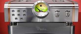
An excellent example of the above is the Octave V 16 Single Ended tube amplifier. The words Single Ended in the name are translated as “single-ended”, which is a technical description of the operating mode of the lamps and, in fact, is synonymous with the concept of “class A”.
In order to invigorate the classic circuit design and bring the amplifier's performance characteristics closer to modern realities, Octave developers have implemented several original solutions that correct the operating mode. Adaptive three-stage amplifier mode control controls the amount of bias current based on the maximum amplitude of the incoming signal, so as not to keep the amplifier circuit in a high-power mode unnecessarily.
And when there is no signal at the input for more than two minutes, the Ecomode mode is activated, which reduces power consumption by up to 35%. Thus, an amplifier left unattended will not heat up the room to no avail.
The developers fought for sound quality no less than for energy efficiency, so they used high-tech transformers with magnetic field compensation, advanced pre-amplifier stages that expand the range of reproduced frequencies, as well as the most advanced stabilization circuits that eliminate noise and hum, which class A amplifiers enjoy demonstrated even with a slight deviation from operating parameters.
As a result, the amplifier can be used with completely different loads: from low-impedance acoustics to high-impedance headphones, without fear of damaging them or simply going beyond the operating mode. Tracking electronic circuits reconfigure the output stages automatically.
Reading this, it’s time to get inspired and decide that absolutely all problems have already been solved by modern engineers. But don’t rush, because you need to look at your passport details. And there a very specific picture emerges. With low levels of noise and distortion, having nearly two dozen kilograms of live weight and consuming up to 200 W from the network, Octave V16 Single Ended produces no more than 8 W per channel on acoustics with an impedance of 4 Ohms when using the most powerful lamps. This is quite enough for headphones, but where to look for suitable speakers?
Tube amplifier circuits. Part 1. From Hi-Fi to High-End
AS AN INTRODUCTION
Experts and observers are unanimous that Hi-Fi amplifiers, replicated in mass equipment and available to everyone, have ceased to be the standard of quality. In Soviet jargon, Hi-Fi correlates with High-End'oM as "Khrushchev" and today's "improved-plan houses". However, it is unlikely that it will be possible to draw an exact boundary between these two categories of equipment. After all, on the one hand there is super Hi-Fi, and on the other - affordable High-End, which even sound tasters cannot distinguish by the quality of the finished product - the sound of voices and music. For example, we know that there is an equal final rating given to both the obviously High-End amplifiers of the Octave V50 and Arion Acoustics Adonis, and those similar in price, but, judging by the advertising, the clearly Hi-Fi amplifiers of the Musical Fidelity set and the mysterious JA Michell Engineering Alecto. For our places, firmly forgotten by the god of progress, we can draw an analogy with the situation in radio electronics in Soviet times. On the one hand, there is the powerful radio industry with its “medium gray consumer goods”, always unable to keep up with the chariot of progress, and on the other, amateur radio designers with single copies of high-quality equipment. And, conversely, on the one hand, there is well-established factory technology, and on the other, cigarette ash on the circuit board, perhaps a glass of vodka, or maybe unwashed hands after eating lard... The combination of these conditions did not give a win to either side. In that world that is still otherworldly for most of us, times have long since changed, so we can confidently consider High-End equipment to be something like homemade products made in a factory, or a professional approach to amateur radio design (for us it has always been the equivalent of a creative approach !). And, most likely, these are not so much original circuit solutions as careful technological finishing of non-serial or small-scale copies of handmade devices. True, there are two significant features that arise from the combination of the above-mentioned opposites. The first of them is a clear disregard and widespread violation of all kinds of “taboos”, of which there are a great many in practical radio electronics, in order to achieve a given sound quality. The second is associated with the extremely high cost of the equipment, which allows the use of any non-trivial, and sometimes simply exotic, approaches to circuit and technological solutions. In the light of this approach, the most striking features in the High-End class are audio frequency power amplifiers (AFPA), speaker systems and playback devices, especially for vinyl discs, although interesting solutions for CD players are not excluded. So, by its unusual appearance, the High-End UMZCH is immediately recognizable, but this is not our topic. The main thing is that we immediately see lamps protruding outward from the body of the overwhelming majority of designs. This can be either an entire tube amplifier or a tube power stage, but removing transistors from high-end equipment is a general trend, although exceptions do occur. The same general task is to ensure the linearity of the amplification mode, for which they use the operating mode of the first kind or class A (without cutting off the anode current) or, in extreme cases, AB, although the latter at maximum powers reminds of its nonlinearity by the appearance of “step” type distortions. The structural diagram of the UMZCH is “to tears” simple, it is known to everyone who is at least a little familiar with this matter. Several inputs are switched by a conventional bib, although the Hi-Fi already has electronic switches controlled from a common remote-controlled processor. The signal first goes to the pre-amplifier, and then to the output stages of the UMZCH. The load of the amplifier is acoustic systems or speakers connected through a matching device, which corrects the frequency response of the amplification path and can be located both in the UMZCH housing and in the speakers. Typically, the load resistance is in the range of 1...16 Ohms, so the output power of the amplifier varies when connecting different speakers. It is considered ideal for this class of equipment to reduce the power by half when the load resistance is reduced by half. The amplifier is covered by negative feedback (NFB) with varying degrees of depth and coverage: either the entire UMZCH, or part of the cascades, or a multi-loop NFO is installed - everything depends, on the one hand, on the necessary stability of the circuit, which the NFO gives it, and on limiting the magnitude of the inevitably increasing dynamic distortion with increasing OOS depth on the other hand. So, we have already touched on general “taboos” that usually do not matter when designing High-EncTa. This is also an extremely low efficiency of about 10...15% of terminal stages operating in class A mode. This is also a return to the use of lamps, which inevitably causes the use of output transformers - the thunderstorm and scourge of designers of the bygone era of lamp technology. And if you add a power transformer and power filter chokes, you get a powerful set of sources of low-frequency magnetic fields. However, the technology is modern, and the old problems have gone away on their own: the transformer is made with a power reserve, is tightly packaged and encased in a casing, it does not heat up and does not hum. And the output transformer is also so broadband, with a uniform frequency response, that its influence is not noticeable at all. Another “taboo” on increasing weight and dimensions is forgotten when using wall-mounted installations. Soldering some parts on the contact petals of ceramic lamp sockets, and others on mounting bars made of solid copper rods, in principle, does not save volume, but there is no influence of circuit elements on each other, as with close printed wiring. Here, something completely unthinkable in the old days, and for today’s Hi-Fi too, was used, connecting blocks, boards and nodes to each other with multi-core wires, massively reminiscent of power ones. Gather 5-7 varnished wires with a diameter of 0.1 mm into one bundle, and then braid a braid of 7-11 such bundles, cover it all with an insulating tube and cover it with a copper braid wound on an aluminum screen. This or something like this is how wires are made both for installation work and for connecting equipment with cables inside the kit. For the latter, you need good terminals and connectors that do not oxidize, fit tightly, are durable, in a word, only one metal is suitable for their manufacture and they call it gold. But this is already in the realm of exotic things that can be bought for a lot of money. And here’s another “taboo”, or superstition, or spell, whatever you want to call it, and it concerns push-pull cascades. Their theoretical parameters are excellent, but practice has shown that the asymmetry of the excitation circuits and amplification arms significantly distorts the reproduced sound, so more and more often in our time they are returning to a single-ended circuit of the output stage, as in the Art Audio Diavolo UMZCH, the circuit of which is shown in Fig. 1. She and more reliable, more stable, and less capricious in tuning than a two-stroke. But still, in High-End the latter not only does not lose ground, but also at a high level of technology allows you to realize all its advantages, including lower output impedance, improved filtering of higher harmonics in the load (for class AB mode), lower requirements for filtering variable components in the power circuit. The diagram of a typical push-pull output stage of the Jadis DA5 UMZCH in all respects is shown in Fig. 2.
Figure 1 Tube single-cycle UMZCH Art Audio Diavol - circuit diagram
Figure 2 Schematic diagram of the Jadis DA5 push-pull tube power amplifier
Two types of environmental feedback are also shown here: local on the shielding grid and deep on the control grid of the first stage of the UMZCH. The output power level at different speaker impedances is selected by connecting the anode circuit to different terminals of the transformer. To reduce the background of the power supply network, a balun potentiometer is included in the filament circuit. It should be noted that the first stages are designed to provide the required minimum noise, and the subsequent stages provide the necessary amplification using a differential cascade design, as is done in the Jadis DA5 (Fig. 3). As we see, another taboo has been broken - instead of isolating capacitors, which have always been installed in lamp cascades, a galvanic connection has been made, which for the designer is an extra headache when calculating modes, and for listeners of these wonders of the world - a balm for the soul, since there are no distortions from - for separators limiting the signal spectrum.
Figure 3 Fragment of the Jadis DA5 tube amplifier circuit diagram
And here’s another “wrong” solution - there are no preamps and tone controls. The reason for this is the uniform frequency response, because in such devices the harmonic coefficient does not exceed a tenth of a percent, and the unevenness of the frequency response does not exceed a fraction of a decibel. This principle of UMZCH layout can be called no-frills design, and Sony also joins it: in its most recent amplifier developments, instead of stereo amplification channels, there is dual mono. Presumably, the quality of recording on CD media and the width of the stereo base make it possible to do without channel balance. However, as experts say, the stereo effect can be obtained even from monophonic devices, if, of course, there are at least two of them. There is one significant drawback of Hi-Fi equipment, the elimination of which in High-End amplifiers should be considered an achievement of progress. For Hi-Fi, experts recommend placing the final amplification stages in speaker boxes. And this is not to save space. The fact is that in power amplifiers with strong negative feedback, as the capacitive load increases, phase shift phenomena are observed, as a result of which parasitic positive feedback occurs instead of negative feedback. If both amplifiers were placed together, it would be impossible to do without a wire connected to the output of the amplifier and going to the loudspeaker; This wire, under some circumstances, may just turn out to be such a capacitive load. Thus, by placing the loudspeakers and the Hi-Fi power amplifier together, the dimensions of the device with switching, four program sources and a pre-amplifier are reduced, and on the other hand, unwanted phase shift in the power amplifier is eliminated in the loudspeaker block. All this is unimportant for High-End UMZCH, in which the load capacitance is technologically compensated. In general, special care must be taken when using shielded wire. It is completely wrong to shield every wire that carries an audio frequency. In this case, excessive precautions only bring harm, because the screen and the wire core form a capacitive shunt, which in high-impedance circuits inevitably causes losses at higher audio frequencies. When designing a chassis, we must strive to make do with a minimum of shielded wire. To achieve this goal, it is necessary to shorten as much as possible all wires carrying sound frequencies. If you make sure that the wires going to the inputs of the pre-amplifier stages are not located too close to each other, then basically only the control grid circuit of the first pre-amplifier tube will have to be shielded. In doubtful cases, it is better to install a metal screen 5-10 mm from the “suspicious” wire rather than using a shielded wire, since in this case the stray capacitance of the installation will be less. These rules do not apply to High-End amplifiers, because in them the internal installation and connection of the amplifier to the speaker are carried out with special multi-core wires, which have already been mentioned above. By the way, there are reports from radio amateurs that they changed the connecting wires in their old designs to new ones and received a completely unexpected improvement in sound quality. This only confirms the well-known truth that everything new is well-forgotten old.
Simple circuits
Our parade of High-End circuitry opens with V. Borisov’s single-tube amplifier (R-3/76) on a 6F5P type lamp, in a cylinder of which there are two independent lamps - a triode and a pentode with a common filament. The triode is used in the voltage pre-amplification stage, the pentode in the power amplification stage. Amplifier sensitivity 100 mV. Output power measured at 1000 Hz input: -1.5 W with less than 3% THD. The frequency band of uniformly amplified oscillations is 50…20,000 Hz. The amplifier input can be supplied with a signal from a piezoelectric pickup or from other sources of audio frequency signals. To be honest, this circuit is recommended by the author for beginners, however, it has all the signs of High-End circuitry, if, of course, you add the appropriate technology. Yes, and you need to start somewhere. So, the circuit diagram of the amplifier is shown in Fig. 4. The audio frequency voltage is supplied to the two-socket block LU1, in parallel with which a variable resistor R1 is connected, which is a volume control. From the resistor motor, the signal is supplied to the control grid of the L1a triode and amplified by it. The higher (according to the diagram) the resistor slider is located, the greater the signal voltage on the control grid. By the way, the designations on the diagram and images of the elements are made in the standards that were used at the time of publication of the materials used.
Figure 4 Schematic diagram of a High-End single-tube amplifier by V. Borisov
For normal operation of the radio tube, it is necessary to apply a negative bias voltage relative to the cathode to its control grid. In this amplifier, the initial bias is formed when the anode current passes through resistors R3 and R4. The control grid of the triode is connected through resistor R1 to a “grounded” conductor and, therefore, a negative voltage acts on it relative to the cathode, equal to the voltage drop across the cathode resistors -1.7 V. Due to the introduction of resistors R3 and R4 between the cathode and the control grid of the lamp Negative AC feedback occurs, reducing the gain of the cascade. To weaken the effect of this feedback, a capacitor C1 is connected in parallel with resistor R3. Resistor R2 acts as a load for the anode circuit of the triode. The amplified signal voltage created across it is fed through the isolation capacitor C2 to the control grid of the pentode L1b. The low-frequency signal amplified by it is supplied through the output transformer Tr1 to the voice coil of the electrodynamic head of direct radiation Gr1 and is converted by it into sound vibrations. Resistor R8 and capacitor C7 of this stage perform the same function as similar parts of the first stage. With the help of capacitor C6 and resistor R6, negative feedback on alternating current is created, which is necessary to regulate the timbre of sound in the high frequency region. The higher (according to the diagram) the motor of the variable resistor R6 is located, the greater the feedback voltage is supplied to the pentode grid, the lower the gain of the cascade at higher frequencies of the operating range. In such cases, the high frequencies of the amplified signal are said to be “cut off.” Resistor R9, connecting the ungrounded terminal of the secondary winding of the output transformer with resistors R3, R4, creates a second negative feedback circuit. By covering both stages, it allows for more uniform signal amplification across the entire operating frequency range and reduces nonlinear distortion. The amplifier is powered from an alternating current network with a voltage of 220 V. The power supply is formed by a transformer Tr2 and a full-wave rectifier using diodes D1-D4 connected in a bridge circuit. Rectified voltage ripples are smoothed out by capacitor C8. A constant voltage is supplied to the anode of the L1b pentode (through winding I of the output transformer) directly from the capacitor C8, and to the pentode screening grid through the decoupling filter R7C4. The anode voltage is supplied to the first stage of the amplifier through an additional decoupling filter R5C3. The use of decoupling filters prevents parasitic feedback between stages through a common power supply. Incandescent lamp L2, connected in parallel with winding III of the transformer, serves as an indicator that the amplifier is turned on. For the power supply, you can use a transformer with a power of 40-60 W of any type, including those from tube receivers or radiograms. On winding II there should be an alternating voltage of 190-210 V, on filament winding III - 6.3 V. You can also use a homemade transformer made on a Ш22Х40 core. For a network voltage of 220 V, winding I must contain 1040 turns of PEV-1 0.25 wire, winding II - 965 turns PEV-1 0.15, winding III - 34 turns PEV-1 0.6. Output transformer Tr1 - TVZ-2-1 (unified output transformer for the audio channel of televisions). It can be replaced with a transformer from any tube radio or TV with a single-ended output stage in the low-frequency amplifier. Most of the fixed resistors and electrolytic capacitors C1 and C7 are mounted on a homemade circuit board located in the basement of the chassis near the lamp socket. Capacitor C2 is soldered directly to terminals 1 and 9 of the lamp socket (Fig. 4), capacitor C5 is soldered to the terminals of the primary winding of the output transformer, resistors R7 and R5 are soldered to the terminals of the positive plates of capacitors C8, C4 and S3. The fuse holder with fuse and power switch B1 are located on the rear wall of the chassis. We should not forget that the amplifier's power supply circuits operate at fairly high voltages. Therefore, when starting to test and set up an amplifier, you must be especially careful and, of course, not touch conductors with high voltage. When replacing parts or making changes to installation, the amplifier must be disconnected from the mains. After checking the installation according to the schematic diagram, resistor R9 should be unsoldered from resistors R3 and R4, and capacitor Sb should be unsoldered from the pentode anode. 40-50 s after turning on the power, when the cathodes of the lamp warm up, a weak background of alternating current should appear in the head, which is a sign of the operability of the power supply and the output stage of the amplifier. If now the motor of the variable resistor R1 is placed in its uppermost (according to the diagram) position and its ungrounded terminal is touched, for example, with tweezers, then an alternating current background should appear in the head. This is a sign of the performance of the amplifier as a whole. Now the volume control slider should be placed in the lowest position (according to the diagram), measured and, if necessary, adjusted the operating modes of the lamp. The recommended voltages at its electrodes, indicated on the circuit diagram, are measured relative to the common (“grounded”) power conductor with a voltmeter with a relative input resistance of 10 kOhm/V. Without compromising the operation of the amplifier, these voltages can be 15...20% higher or lower. If the measured voltages; are significantly overestimated, you should introduce an additional decoupling filter R10C9 between the rectifier and the amplifier (it is shown in Fig. 4 with dashed lines) and select the required voltage with resistor R10 (it should be 1 W). The bias voltage at the triode cathode is selected with resistor R3, and at the pentode cathode with resistor R8. Then you can connect a pickup to the amplifier input and play the record. The sound should be loud and change smoothly as you rotate the variable knob of resistor R1. When the connection between resistor R9 and the cathode circuit of the triode is restored, the sound volume of the head will decrease slightly and the sound quality will improve. If, after connecting resistor R9, self-excitation of the amplifier appears, it means that positive feedback has arisen between the output and input stages and the amplifier has turned into a low-frequency oscillation generator. To eliminate this phenomenon, it is enough to swap the connections of the terminals of winding II of the output transformer. After restoring the connection of capacitor C6 with the anode circuit of the pentode and checking the smoothness of the sound timbre control with variable resistor R6, the setup of the amplifier can be considered complete. To begin with, we have given a detailed description of the principle of operation, design and configuration in order to have an example of how to work on your own design. In the future, those details that may well be replaced by the personal experience of a radio amateur will be omitted, and more attention will be paid to the nuances of the circuit and design features.
Many circuits developed by radio amateurs were designed for record players, especially portable ones. This is explained by the fact that historically the first UMZCHs were placed in gramophones, and the so-called radiogrammaphone was obtained. An example of such a circuit, which was powered from a 220 V network, was the two-tube amplifier by V. Mikhailov (BZHR-5/59), shown in Fig. 5. This circuit is with an open input, like the previous one; in addition, there are other similarities between both designs, so let’s pay attention to the features.
Figure 5 Schematic diagram of a single-ended tube amplifier by V. Mikhailov
Firstly, there is no deep OOS from the amplifier output to the input, there is only local OOS in each stage - these are R2 and R6, which do not have blocking capacitors. Secondly, the power supply of the circuit, the output power of which at a nonlinear distortion coefficient of 3% is 4 W, is carried out according to a single-cycle circuit, therefore the anode winding Tr2 has the same number of turns as the primary network winding. A design feature of the UMZCH installed in radiogramphones is its location away from the drive motor, as far as possible in the limited volume of the suitcase in which the entire circuit is enclosed. An additional factor that protects the UMZCH from interference from the engine is the shielding of the wire running from the pickup to R1 and further to the L1 grid, as well as the entire amplifier as a whole.
The circuit of E. Dodonov’s battery player (R-5/61), which is shown in Fig. 6, looks different from the previous ones. Judging by the name, the device is powered by a battery, most likely a rechargeable one, for which a 150 V AC converter-generator is included in the power supply.
Figure 6 Schematic diagram of a tube amplifier with an E. Dodonov converter
Two low-power lamps allow you to get 1 W at the amplifier output, which with a fairly high efficiency. amplifier is not too ruinous for the battery. High efficiency is obtained by switching the final stage of the amplifier to class C operating mode with a cutoff angle of about 60 degrees. The power reserve is not fully realized, since to reduce distortion, an OOS is introduced from the output winding of the transformer Tr1 to the cathode of the input lamp L1 through the chain R14-C6. The first stage uses a 6Zh5P lamp, which has a fairly high slope of the static current-voltage characteristic compared to other low-power pentodes. The filaments of the lamps are powered directly from the DC battery, so the filaments of both lamps are connected in series. To eliminate self-excitation along the power supply circuit, use capacitors SZ, C5, C8, and resistors R12, R13. The power converter is assembled on P4B pulse transistors, which can be replaced with any pnp transistors with a maximum permissible power of 10 W.
A peculiar development of the single-tube theme is a simple stereo amplifier (Fig. 7), given by G. Gendin in the literature “Homemade ULF”, MRB, 1964. It uses a 6FZP type triode-pentode, which allows you to develop a power of 1.5 W in a frequency band of 60 …12000 Hz with an input signal of 250 mV.
Figure 7 Schematic diagram of a stereo tube amplifier by G. Gendin
This amplifier is made entirely for use in stereo sound. For this purpose, the volume control resistor R1 is made double, and in the cathode circuit of the first stage there is a resistor R6 to adjust the stereo balance between the channels. An immediately noticeable drawback is that when playing monophonic programs, only one channel works, while the second simply warms the atmosphere. The lack of feedback covering the entire amplifier creates the risk of self-excitation, so the amplifier has taken strict measures to prevent it. Firstly, in the power circuit there is a filter with a cutoff frequency of 100 Hz, consisting of inductor Dr1 and capacitors C7, C8. Secondly, in the input circuit of the first stage, OOS is implemented through chains of resistors R4, R2 and a balanced resistor R6. Thirdly, the OOS operates on the grid of the second stage through the divider R7-R8. To reduce the influence of temperature instability of the filament voltage on the parameters of the lamps, 100 Ohm trimming resistors R11 are connected parallel to the filament windings, made separately for each lamp. Their midpoint is connected to ground through resistor R13, which is part of the anode supply voltage divider R12-R13. This connection creates a positive bias of 20...30 V at the midpoint of the filament winding and makes it possible to suppress low-frequency background due to filament voltage pickup in the useful signal circuit. As an output and power transformer, you can use the same ones as described in V. Borisov’s circuit, adding an additional filament winding to the power transformer.
A more advanced version of this scheme is the stereophonic set-top box by A. Vorobyov-Obukhov, which is designed for playing stereophonic recordings using a conventional monophonic system (R-10/72). This is already a rather complex amplifier, but it still retains such formal features of simplicity as, for example, the presence of a single tube in the channel, low power, and a limited number of parts. The operation of the set-top box is based on the property of the stereo effect to appear at frequencies above 200-300 Hz. This phenomenon allows you to use a mono amplifier to amplify frequencies below 200-300 Hz, and to amplify frequencies above 200-300 Hz - two simple amplifiers of a set-top box with a stereo speaker system. The design of speaker systems in this case is dramatically simplified, since most of the complications in them are caused by the need for good reproduction of frequencies up to 200-300 Hz, which you don’t have to worry about, since a separate low-frequency amplifier successfully copes with this task. The console (Fig. 8) contains two single-tube amplifiers using lamps L2 and L2′ and a mixing stage using lamp L1. When playing a record, the low frequencies of the right and left channels of the pickup go to the mixing stage and then to the input of the low-frequency radio amplifier. High frequencies of the right and left channels are amplified by separate amplifiers of the low-frequency set-top box. Low frequencies are filtered by the C6R6, C6'R6' chains and the automatic bias circuit, thanks to the small capacitance of the capacitors SZ, SZ' and C4, C4'. Potentiometers R2, R2′ are used to adjust the volume. Using potentiometers R10, R10′, you can set the stereo balance and the required maximum power by adjusting the depth of feedback in the amplifiers of the set-top box. The output of the mixing stage is designed for connection to an amplifier with an input impedance of at least 470 kOhm. The console is powered by the amplifier's rectifier.
Figure 8 Schematic diagram of a tube amplifier by A. Vorobyov-Obukhov
During installation, special attention should be paid to shielding the signal circuits of the console lamps. The cord connecting the output of the set-top box to the amplifier must be made with a shielded wire. It makes sense to ground the middle point of the filament winding of the amplifier's power transformer, or apply a positive bias of 10-20 V to it from the anode power source, as in the previous circuit. Speakers should have a voice coil impedance of 4-6 ohms. Paired resistors SP-3-7 are used as potentiometers R2, R2′.
The next UMZCH without an output transformer by L. Kononovich (R-b/59), with even greater stretching, can be called simple. It contains three lamps, a fine-compensated volume control, a separate tone control for low and high frequencies and a unique output stage circuit assembled from series-connected 6P18P type lamps, which is called “Tandem” (Fig. 9). The possibility of turning on a loudspeaker without a transformer in such circuits is explained by the fact that in the presence of a high-capacity capacitor C14, both lamps L2 and LZ are connected via alternating current in parallel, which reduces the output resistance of the “Tandem” to a value less than the resistance of the leading lamp L2. Its mode is chosen in such a way that the output impedance of the cascade is close to 100 Ohms, and its load is served by two speakers connected in series, 16 Ohms each.
Figure 9 Schematic diagram of a tube power amplifier by L. Kononovich
Such circuits were not widely used, because it is not possible to obtain an output impedance of less than 600...1000 Ohms in powerful stages, and special high-impedance loudspeakers are required to connect to them. In this circuit, due to the approach of the L1 lamp mode to saturation, a significant mismatch between the output resistance and the load, and the presence of deep feedback from the amplifier output to the cathode of the L1b lamp, the output power is reduced to 2 W. The advantages of this circuit include a wide band of amplified frequencies of 30...20000 Hz, which is limited only by isolation capacitors. Also a positive quality is the large depth of tone control, which reaches 20 dB. And finally, a significant advantage is the large margin of stability of the amplifier over the entire frequency band. The listed advantages ensure high sound quality of the UMZCH.
To conclude the review of simple circuits, we present a “foreign” example of amateur radio creativity, which was published in R-1/65. This is a stereo amplifier from the Bulgarian I. Kusev. The amplifier (Fig. 10) is designed for stereophonic and monophonic playback of programs from radio broadcasting stations and gramophone records. The maximum output power of each amplifier channel is 6 W with a nonlinear distortion coefficient of no more than 1%, rated power 1.5 W, with a nonlinear distortion coefficient of no more than 0.8%.
Figure 10 Schematic diagram of a stereo tube power amplifier by I. Kusev
Depth of tone control of lower sound frequencies at a frequency of 20 Hz/dB. Depth of timbre adjustment of higher sound frequencies at a frequency of 16 kHz +12 dB. The amplifier reproduces an audio frequency band of 20...16000 Hz with an uneven frequency response of no more than 0.5%. The first stage of both channels of the amplifier is made using two triodes of the ECC82 lamp according to the cathode follower circuit. Frequency response regulators R9 - R10 are turned on at the inputs of the second amplification stages. This regulator should be given special attention, since it allows you to change the frequency response of the amplifier without reducing the amount of feedback. The tone controls of higher R25, R25a, and lower R21, R22 audio frequencies are included in the frequency-dependent feedback circuit between the second and third stages of the amplifier. The stereo balance control R37 is connected between the third and fourth stages of both amplifier channels. The last two stages of the amplifier are covered by frequency-dependent negative feedback with a depth of 20 dB. The feedback voltage from the secondary windings of the output transformers is supplied to the cathode circuits of the lamps of the pre-final stages of the amplifier. In addition to smooth, the amplifier has a stepwise tone control in four positions: “normal”, “orchestra”, “speech”, “bass”, which allows you to obtain the desired sound timbre of both higher and lower sound frequencies. The output stages of each amplifier channel are made using EL84 tubes using an ultra-linear circuit. Each amplifier channel is loaded with two loudspeakers 6 W and 1.5 W. To improve the sound of the speakers, it is recommended to slightly alter them, guided by the sketches shown in Fig. 11
Figure 11
The ECC82 lamp can be replaced with a 6N1P lamp, the ECC83 lamp with a 6N2P lamp, and the EL84 lamp with a 6P14P lamp. The EZ81 kenotron is replaced by two 6Ts4S kenotrons connected in parallel or one 5TsZS kenotron. In relation to domestic lamps, the parts have the following data. The output transformer Tr1 (Tr2) is assembled on a core made of Sh-20 plates, the thickness of the set is 25 mm (window area 5.4 cm2). Its primary winding contains 2500 turns of PEL 0.18 wire. The tap to the shielding mesh is made from the 500th turn, counting from pin 2. The secondary winding consists of two sections connected in series: 57 turns of PEL 1.0 wire and 60 turns of PEL 0.12. The terminals of the first section are connected to terminals P, to which the load is connected - two parallel-connected loudspeakers ZGD-2 (or 4GD-2). A 120 W power transformer is assembled on a core made of Sh-30 plates, the thickness of the set is 48 mm, the window area is 14.6 cm2. The windings contain: network - 440+320 turns of wire PEL 0.69 + PEL 0.51; boost - 870+870 turns of PEL wire 0.25; kenotron filament - 19 turns of PEL 1.2 wire; filament lamps: 24 turns PEL 0.96 and 24 turns PEL 0.72. The Dr1 filter choke is assembled on a Ш-19хЗО core, the gap is 0.2 mm. Its winding consists of 4500 turns of PEL 0.22 wire. The chokes in the network winding circuit of the power transformer each contain 110 turns of PEL 0.12 wire. They are wound on SCG-2 carbonyl cores.
FURTHER
Sound
Since this text is part of a large series of publications devoted to various types of amplifiers, in the process of its preparation one large comparative audition was conducted, in which amplifiers of various classes participated. To give the listening experience a sufficient degree of objectivity, two models of floor-standing speakers were chosen.
One of them was a deliberately heavy load with low sensitivity - a large, tight bass driver, and required high power input. The second was intended to be the other side of the coin: an extremely light load that could work with any, even low-power, amplifier. And in all cases, this testing scheme was quite working until the Octave V16 Single Ended appeared on the scene with its 8 W per channel.
Under heavy load, the distortion was so real that it seemed you could touch it, and the load, previously known as light, successfully coped with the role of heavy. In the absence of another pair of speakers with a power of several watts and a sensitivity above 100 dB, headphones played the role of a light load.
With speakers that require at least 25 W according to their passport, the Octave V16 Single Ended worked surprisingly well. If you do not abuse the volume, you can fully appreciate the lively, open and clear sound, which is simply excellent on quiet audiophile recordings.
The situation becomes more complicated when it comes to more dynamic music, and on rock songs the amplifier happily dumps the sound of guitars into mush, giving as a bonus audible compression. The only saving grace is the fact that compression and distortion performed by tubes, unlike transistors, gives the sound a rather pleasant coloration.
If you try to reduce the load on the amplifier, lower the volume, and then sit closer so as not to lose sound pressure, the picture is corrected. There is no dirt, there are more parts, and compression is not felt. Here I will note that this amplifier is quite small in size; it can be placed not only in a rack, but even on a table, for use with headphones and near-field bookshelf monitors.
It was possible to fully experience the amplifier's belonging to the High End category through headphones. Absolutely crazy detail, open, spacious and timbre-rich sound, controlled and clear bass - everything you can dream of. And, characteristically, even with fast, heavy music, the amplifier began to behave with dignity. No imposingness, no mess, no booming in the low-frequency range. This is what it means to provide a class A amplifier with optimal operating conditions.
Class D audio amplifiers: features and benefits. Part 1
Class D amplifiers have become very popular in recent years, although they were first introduced back in 1958. What are Class D amplifiers? How are they different from other types of amplifiers? Why is this class particularly well suited for audio applications? The answers to all these questions are contained in this article.
Benefits of Class D Amplifiers
The job of audio amplifiers is to transmit the audio input signal to the audio reproduction system at the required volume and power level—accurately, efficiently, and with little interference. Audio frequencies are the range from 20 Hz to 20 kHz, so the amplifier must have a good frequency response throughout the entire range (or in a narrower area if we are talking about a speaker with a limited playback bandwidth, for example, a mid-range or tweeter in a multi-band system). Powers can vary (depending on the specific device): milliwatts in headphones, watts in television sound systems and PC audio, tens of watts in home and car sound systems, hundreds or more watts in powerful home and concert sound systems. Conventional analog audio amplifiers use linear-mode transistors to generate an output voltage that accurately scales the input voltage. The voltage gain is usually quite high (about 40 dB). If the forward gain is included in the feedback circuit, then the gain of the entire feedback circuit will be large. Feedback in amplifiers is often used because high gain in combination with feedback improves the quality of the amplifier: it suppresses distortion caused by nonlinearities in the forward circuit and reduces noise from the power supply due to the fact that the power supply effect ratio (PSRR) is reduced. In a conventional transistor amplifier, the output stage transistors provide a continuous signal at the output. There are many different designs for audio systems: Class A, AB and B amplifiers. All, even the most efficient, linear output stages have greater power dissipation than Class D amplifiers. This property of Class D amplifiers gives them an advantage in a variety of systems, such as how low power dissipation means less circuit heat, saves board space, reduces cost, and extends battery life in portable devices.
Comparison of amplifiers of different classes
As a rule, the output stages of linear amplifiers are directly connected to the loudspeaker (only sometimes through a capacitor). If bipolar transistors (BTs) are used in the output stage, they usually operate in linear mode, with a high voltage between the collector and emitter. In addition, the output stage can be implemented using MOSFETs, as shown in Figure 1. In linear output stages, power is dissipated because the generation of VOUT inevitably leads to non-zero IDS and VDS values in at least one of the output transistors. The amount of power dissipated depends on the amount of bias of the output transistors.
Rice. 1. Linear output stage based on MOS transistors
In Class A amplifier circuits, one of the transistors is used as a constant current source, providing the maximum amount of current that can be required by the speaker. As a result, good sound quality can be achieved with Class A amplifiers, but the energy loss in such circuits is extremely high due to the fact that a large direct current flows through the output transistors (it is of no use here), and through the loudspeaker, where it actually flows , and is needed, the current does not pass. In Class B circuits there is no bias current and therefore much less energy is dissipated. In devices of this class, the output transistors operate in push-pull mode, that is, the transistor MH “supplies” current, and the transistor ML “discharges”. However, the sound quality when using class B circuits leaves much to be desired due to nonlinear distortions (such as “steps”) that occur when switching transistors. Class AB is a compromise - a combination of class A and class B; There is a constant bias current here, but much less than in Class A circuits. Using a low bias current avoids “step” distortion, achieving high sound quality. The power loss in this class of circuits falls between that of Class A and Class B, but is typically only slightly greater than that of Class B amplifiers. A Class AB amplifier circuit is similar to a Class B amplifier and is capable of delivering or sinking large output currents. Unfortunately, even in successful class AB designs, power loss remains significant due to the fact that the average output voltage is very different from the supply voltage. A large range of drain-source voltage changes leads to large values of the IDSVDS product, and therefore to large power losses. Class D amplifiers, thanks to a fundamentally different topology, are characterized by uniquely low power loss compared to all the types of devices mentioned above.
Rice. 2. Class D amplifier circuit without feedback circuit
In a Class D amplifier circuit (see Figure 2), the output voltage of the amplifier is switched between positive and negative power supplies, and thus a train of pulses is observed at the output. This waveform contributes to low power loss, since no current flows through the output transistors when they are closed, and when they conduct current, the voltage value VDS is small, therefore the product IDSVDS is also small. Since most audio signals are not a series of pulses, a Class D amplifier circuit necessarily includes a modulator that converts the audio signal into a pulse signal. The pulse spectrum includes both the audio signal itself and significant high-frequency components caused by the modulation process. There is usually a low-pass filter (LPF) between the output stage and the speaker to minimize electromagnetic interference and prevent high-frequency signals from being fed to the speaker.
Rice. 3. Differential switching output stage with inductive-capacitive low-pass filter
The filter (see Fig. 3) also must not allow power losses in order to maintain the gain that the switching circuit of the output stage provides. As a rule, capacitors and inductors are used in the filter, and the only element where power loss occurs is the speaker. Figure 4 compares the theoretical output stage power dissipation (PDISS) of Class A and Class B amplifiers with the measured power dissipation of the AD1994 Class D amplifier.
Rice. 4. Power loss in the output stages of class A, B, and D amplifiers
Power dissipation is calculated based on the output power (PLOAD) delivered to the speaker when the audio signal is sine wave. The output power is normalized to the PLOAD max level, at which the sinusoidal signal is “cut” from above so that the total harmonic distortion factor is 10%. The vertical line shows the PLOAD power at which the “cutting” of the sine wave begins. The figure shows that significant differences in power dissipation are observed over a wide range of load power and are especially pronounced at heavy and medium loads. At the beginning of the sine cutoff, the losses in the output stage of a class D amplifier are 2.5 times less than in the class B stage and 27 times less than in class A. It is worth noting that in the output stage of a class A amplifier the energy loss is greater, than in a loudspeaker - this is the result of using a large DC bias current. The efficiency of the output stage (Eff) is determined by the expression:
Eff = PLOAD /(PLOAD+ PDISS).
At the beginning of the sine cutoff, the efficiency is 25% for class A amplifiers, 78.5 for class B amplifiers and 90% for class D amplifiers (see Fig. 5). The best efficiency values for amplifiers of classes A and B are often given in the literature.
Rice. 5. Efficiency of output stages of amplifiers of classes A, B and D
The advantage of Class D amplifiers is that they allow you to expand the operating power range. This is important for audio reproduction, as long mid-range power levels at high volumes do not utilize the full dynamic range, and short, powerful peaks reach PLOAD max levels. So, for audio amplifiers PLOAD = 0.1. PLOAD max is a reasonable operating power level at which PDISS should be determined. At this level, the power loss in class D amplifiers is nine times lower than in class B and 107 times lower than in class A. For an audio amplifier with a PLOAD max value of 10 W, an operating level of 1 W seems optimal for listening. Under these conditions, the Class D output stage dissipates 282 mW; in class B - 2.53 W; and in class A - 30.2 W. The efficiency of Class D amplifiers at a given power drops to 78% from 90% at higher powers. But even 78% is incomparably better than the efficiency of classes B and A - 28 and 3%, respectively. The differences in efficiency and power dissipation are significant from the point of view of the use of the listed amplifiers. At power levels above 1 W, large heat losses in the linear output stages lead to the need for additional costs for the cooling system. For power levels less than 1 W, the heating from energy dissipation in the output stage is not so significant, but the fact of unnecessary energy loss becomes important here. If the system is powered by a battery, then the line output stages will drain the battery much faster than systems with Class D amplifiers. From the above example, you can see that a system with a Class D amplifier draws 2.8 times less current than Class B amplifiers and 23 times less current than Class D amplifiers. .6 times less than Class A amplifiers - resulting in a significant difference in battery life for devices such as cell phones, MP3 players and handhelds. So far we have only considered the output stage of the amplifier. However, if we consider all the consuming elements of the amplifier system, then linear amplifiers become more serious competitors to class D at low operating powers. The fact is that the power that is spent on generating and modulating a pulse signal is relatively large with a low output power. Thus, the total losses of a well-designed class AB amplifier at a relatively low power can be approximately the same as the losses in a class D amplifier. But at high powers, a class D amplifier has undeniable advantages in terms of power dissipation.
Comparison of differential and single-ended versions
Figure 3 shows a differential option for connecting output transistors in a class D amplifier with capacitive-inductive filters. A full bridge (H-bridge) consists of two half-bridge circuits operating in switch mode, which supply pulses of opposite polarity to a filter consisting of two inductors, two capacitors and a speaker. Each of the half-bridges consists of two transistors: the “upper” MH, connected to the positive power bus, and the “lower” ML, connected to the negative power bus. The diagrams show that pMOS transistors are used as “top” transistors. nMOS transistors are also often used as top-of-the-line transistors; they can reduce gate size and capacitance, but require special control circuitry [1]. Full bridge circuits are typically powered from a single supply (VDD), with the negative power supply (VSS) connected to ground. At the same values of VDD and VSS, the differential circuit provides a gain in signal swing of two times and in power of four times compared to an asymmetric circuit. Voltage surges may occur on the power rails of a half-bridge circuit due to the energy stored in the inductance of the LC filter. The dV/dt rise rate of these transients can be limited by using large capacitors between the VDD and VSS supply rails. A full-bridge circuit does not have this problem, since current flows from one half-bridge to the other, creating a local loop, and thus this current does not affect the supply voltage.
Features of Class D amplifiers
The low power dissipation in Class D amplifiers provides significant advantages when used in audio paths, but developers will certainly be faced with the need to solve the following problems: – selection of output transistors; – output stage protection; - sound quality; – modulation method; – radio interference; – development of an LC filter; – high cost of the system.
Output Transistor Selection
The output transistor is sized to minimize power loss over a wide range of different signal values. The requirement for a small VDS value when passing a large IDS current means that the output transistor must have a low open-channel RON resistance (about 0.1 ... 0.2 Ohms). But this requires a large transistor with significant gate capacitance CG. The circuit that drives the transistor's gate and drives a capacitive load consumes power equal to CV2f, where C is the gate capacitance, V is the change in gate voltage during charging, and f is the switching frequency. These "switching losses" become excessive if the capacitance or switching frequency is high, so there are some practical limitations. Thus, transistor selection must be done by selecting the ideal ratio to minimize current loss (minimum IDS VDS product) and minimize switching losses. RON losses dominate at high power levels, while switching losses have a greater impact at low power levels. Transistor manufacturers strive to minimize the RON CG product in their devices to minimize possible power losses and give engineers the greatest freedom in choosing the switching frequency.
Output stage protection
The output stage must be protected from various potential hazards. Overheating: Thermal losses in the output stages of class D amplifiers, although less than in linear amplifiers, can nevertheless lead to dangerous overheating of the output transistors in cases where the amplifier operates at high power for a long time. A temperature control circuit is used to protect against overheating. The simplest of these circuits turn off the output stage if it heats above the threshold shutdown temperature. The cascade temperature is measured by a built-in sensor. The cascade remains switched off until it cools down. Using a temperature sensor, you can not only turn off the cascade, but also temporarily reduce the volume level when overheating, thereby reducing thermal power loss in the cascade and maintaining the temperature within operating limits. Output transistor current overload: Low on-resistance output transistors do not cause any problems if the output stage and speaker are connected correctly. But if the output is shorted or connected to a positive or negative power rail, very large currents can flow in the circuit. Inattention in this matter can result in damage to the transistors or the rest of the circuit, so current monitoring and protection are necessary. Simple current control systems turn off the cascade at current values above a set threshold. More complex systems implement feedback that configures the amplifier to operate in a safe mode without turning it off. In such circuits, shutdown occurs only as a last resort, when the system cannot configure the amplifier to operate within acceptable limits. Current control systems also make it possible to protect against current surges during resonances in dynamics. Supply voltage reduction: Most switching output stages only work well when the supply voltage is high enough. Problems begin when the supply voltage drops. This moment is controlled by a blocking system, which allows the output stages to operate only when the supply voltage is above a threshold level.
Rice. 6. Transistor control circuit with switching off before switching on
Output transistor turn-on time: The upper (MH) and lower (ML) (see Fig. 6) output transistors have very low on-resistance. Therefore, it is very important to prevent a situation where both output transistors are open at the same time, since in this case a circuit with low resistance will arise between VDD and VSS, through which a large through current will flow through both transistors. At best, they will overheat and power losses will increase, and at worst, the transistors will fail. The turn-on transistor control system prevents the possibility of current through by forcing both transistors off before turning either one on. The time interval during which both transistors are turned off is often called "dead" time.
Sound quality
A few words should be said about how you can achieve high-quality sound using class D amplifiers. The clicking noises that often occur when turning amplifiers on/off negatively affect sound quality. Unfortunately, class D amplifiers also suffer from this problem if you do not pay enough attention to the operation of the modulator, the output transistor control system and the inductive-capacitive filter in the amplifier's on and off modes. Signal-to-noise ratio (SNR): To prevent amplifier noise floor from significantly affecting audio quality, SNR should be 90 dB in low-power portable devices, 100 dB in mid-power devices, and 110 dB in high-power systems. These performance values are achievable in most amplifier designs, but specific noise sources must be monitored on a case-by-case basis to achieve satisfactory overall SNR. Nonlinear Distortion: Nonlinear distortion does not refer to nonlinear effects during the modulation process, but to distortion due to dead time in the output stage, which is necessary to prevent current through-through. The main information about the audio signal is provided by the pulse width at the modulator output. The need to introduce a delay by the amount of “dead” time leads to a change in the pulse duration, and this causes nonlinear distortions proportional to the relative error of the pulse duration. The smallest “dead” time, sufficient to prevent breakdown of the output stage, ensures a minimum level of nonlinear distortion. The work [2] describes in detail a method for minimizing distortions in switching circuits. Other sources of noise include differences in the rise and fall times of the pulses, mismatched timing characteristics of the output transistors, and nonlinear effects in the LC filter. Power Supply Rejection Ratio (PSR): The circuit in Figure 2 shows that power supply noise is transferred directly to the speaker. This occurs due to the low resistance of the output stage transistors. The low-pass filter effectively removes the high-frequency component, but passes all sound frequencies, including noise. A detailed description of the influence of power supply noise in differential and single-ended switching output stages is contained in [3]. Without intentionally addressing harmonic distortion or power supply effects, it is rare to achieve a PSR better than 10 dB or a THD below 0.1%. THD is often the cause of unpleasant-sounding high-order distortion. Fortunately, there are effective ways to solve these problems. Using deep feedback (as is done in many linear amplifiers) often helps. Feedback from the LC filter input significantly improves PSR and reduces any distortion and noise that occurs before the LC filter. Distortion in the LC filter itself can be reduced by including a speaker in the feedback loop. Sound quality with PSR values greater than 60 dB and THD less than 0.01% is entirely achievable in carefully designed closed-loop Class D amplifiers. However, feedback complicates the design of the amplifier, since it becomes necessary to ensure the stability of the amplifier (a non-trivial task for high-order circuits). In addition, analog feedback is needed to monitor pulse width distortions, so the control circuit must contain an analog part to operate the feedback signal. To reduce the cost of an integrated circuit, some manufacturers prefer to cut down the analog part of the circuit or even abandon it completely. Some devices use open-loop digital modulators in conjunction with an ADC to monitor changes in supply voltage, and the modulator's operation is adjusted to compensate for these changes [3]. This method improves PSR, but does not solve the problem of distortion. Other digital modulators try to compensate for pulse duration distortions in advance or take into account the obviously non-ideal characteristics of the modulator itself. This may partially eliminate some of the causes of distortion, but not all. With the help of such techniques, relatively good sound quality is achieved using class D amplifiers without feedback, but feedback is still necessary to obtain the best sound quality.
Literature
1. International Rectifier, Application Note AN-978, HV Floating MOS-gate driver ICs. 2. Nyboe F., et al “Time domain analysis of open-loop distortion in class D amplifier output stages”, presented at the AES 27th International Conference, Copenhagen, Denmark, September 2005. 3. Zhang L., et al "Real-time power supply compensation for noise-shaped class D amplifier", presented at the 117th AES Convention, San-Francisco, CA, October 2004.
The end of the article will be published in “EK2”, 2008.
TOP 5: Best headphone amplifiers – Rating 2022:
| Model | Description | |
| 1. Beyerdynamic A 2 1400$ | The best headphone amplifier under $1500: high quality, class A; | |
| 2. Fostex HP-A3 280$ | Best DAC for headphones under $300: transistor stationary amplifier; | |
| 3. Fiio Olympus 2-E10K 80$ | Best USB headphone amplifier under $100: Fiio external amplifier; | |
| 4. Sennheiser GSX 1000 225$ | Good headphone amplifier from Sennheiser: gaming DAC for computer; | |
| 5. SMSL M6 220$ | Best headphone amplifier under $220: from Aliexpress for PC; | |
5 SMSL M6
The best headphone amplifier under $220, from Aliexpress - for PC
SMSL M6 is the best headphone amplifier under $220. Classic, modest but pleasant design, good switching capabilities and excellent sound for the money. This headphone DAC amplifier sounds detailed, natural, vintage, one might say.
The presentation is quite soft with an emphasis on midbass. The rise in this segment is small; it cannot be said that the bass covers anything. The resolution and dynamic range show that this is far from the most basic headphone amplifier for PC.
- SMSL M6 – the best headphone amplifier from Aliexpress
- Rating of portable headphone amplifiers
+ / —