Inductor is a passive component of electronic circuits, the main purpose of which is to store energy in the form of a magnetic field. The property of an inductor is somewhat similar to a capacitor, which stores energy in the form of an electric field.
Inductance (measured in Henry) is the effect of creating a magnetic field around a current-carrying conductor. The current flowing through the inductor creates a magnetic field, which has a relationship with the electromotive force (EMF) that opposes the applied voltage.
The resulting reaction force (EMF) opposes the change in alternating voltage and current in the inductor. This property of an inductive coil is called inductive reactance. It should be noted that the inductive reactance is in antiphase to the capacitive reactance of the capacitor in the AC circuit. By increasing the number of turns, the inductance of the coil itself can be increased.
Stored energy in inductance
As you know, a magnetic field has energy. Just as there is a reserve of electrical energy in a fully charged capacitor, there is also a reserve of magnetic energy in an inductive coil through the winding of which current flows.
The energy stored in the inductor is equal to the expended energy necessary to ensure the flow of current I in counteracting the EMF. The amount of stored energy in the inductance can be calculated using the following formula:
where L is the inductance, I is the current flowing through the inductor.
Hydraulic model
The operation of an inductor can be compared to the operation of a hydraulic turbine in a flow of water. The flow of water directed through a turbine that has not yet been spun up will feel resistance until the turbine is completely spun up.
Next, the turbine, which has a certain degree of inertia, rotates in a uniform flow, practically without affecting the speed of water flow. If this flow is suddenly stopped, the turbine will still rotate by inertia, creating water movement. And the higher the inertia of a given turbine, the more it will resist changes in flow.
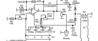
Transistor tester / ESR meter / generator
Multifunctional device for testing transistors, diodes, thyristors...
More details
Also, an inductive coil resists changes in the electric current flowing through it.
Marking
When considering inductors, color and code markings are evaluated. If you look at the first numbers, the inductance indicator is displayed. Next, the deviation parameter is taken into account:
- Silver 0.01 µH, 10%.
- Gold 0.1 µH, 5%.
- Black 0.1 µH, 20%.
- Brown 1.1 µH.
- Red 2.2 µH.
- Orange 1 µH.
- Yellow 4 µH.
- Green 5 µH.
- Blue 6 µH.
- Violet 7uH.
- Gray 8 µH.
- White 9 µH.
Marking
In an unstable alternating electric current circuit, you cannot do without an inductor. The main types of insulated conductors are described above and their parameters are demonstrated. The frequency level is taken into account, as well as properties.
Inductance in electrical circuits
While a capacitor resists changes in alternating voltage, inductance resists alternating current. An ideal inductance will have no resistance to direct current, however, in reality, all inductive coils themselves have a certain resistance.
In general, the relationship between the time-varying voltage V(t) passing through a coil of inductance L and the time-varying current I(t) passing through it can be represented as a differential equation of the following form:
When a sinusoidal alternating current (AC) flows through an inductor, a sinusoidal alternating voltage (EMV) is generated. The amplitude of the EMF depends on the amplitude of the current and the frequency of the sinusoid, which can be expressed by the following equation:
where ω is the angular frequency of the resonant frequency F:
Moreover, the phase of the current lags behind the voltage by 90 degrees. In a capacitor, the opposite is true, where the current leads the voltage by 90 degrees. When an inductive coil is connected to a capacitor (series or parallel), an LC circuit is formed that operates at a specific resonant frequency.
Inductive reactance XL is determined by the formula:
where XL is the inductive reactance, ω is the angular frequency, F is the frequency in hertz, and L is the inductance in henry.
Inductive reactance is the positive component of impedance. It is measured in ohms. The impedance of the inductor (inductive reactance) is calculated by the formula:
Characteristics of elements
The exceptional parameters of this device include the following:
- They have high inductance;
- Suitable for different current strengths, which you need to pay attention to when used in different devices;
- Loss of resistance in conductors, cores, and other elements;
- High efficiency in use;
- Turn capacitance may be parasitic;
- Inductance and its changes affect the temperature coefficients of the device;
- Quality factor values may depend on temperature.
Inductor connection diagrams
Parallel connection of inductors
The voltage across each of the inductors connected in parallel is the same. The equivalent (total) inductance of parallel-connected coils can be determined by the formula:
Series connection of inductors
The current flowing through inductors connected in series is the same, but the voltage across each inductor is different. The sum of potential differences (voltages) is equal to the total voltage. The total inductance of series-connected coils can be calculated using the formula:
These equations are valid provided that the magnetic field of each coil does not affect neighboring coils.
Inductor quality factor
In practice, an inductor has a series resistance created by the copper winding of the coil itself. This series resistance converts the electric current flowing through the coil into heat, which leads to a loss of induction quality, that is, quality factor. Quality factor is the ratio of inductance to resistance.
The quality factor of the inductor can be found through the following formula:
where R is the winding's own resistance.
Tags
features of the inductor. Inductor inductor induction coil current inductor coil work filters induction coil. coil type. spiral coils. suitable coils low frequency inductor. alternating current required current coil alternating current. and chains.
self-inductionandarticlelossvery-calledresponsecircuitssourcespresentsmomentstotalelectromagneticsitegraphics
Inductor. Inductance formula
The basic formula for coil inductance is:
- L = inductance in henry
- μ 0 = permeability of free space = 4π × 10 -7 H/m
- μ g = relative permeability of core material
- N = number of turns
- A = Cross-sectional area of the coil in square meters (m2)
- l = coil length in meters (m)
Direct conductor inductance:
- L = inductance in nH
- l = conductor length
- d = conductor diameter in the same units as l
Air core coil inductance:
- L = inductance in µH
- r = outer coil radius
- l = coil length
- N = number of turns
Inductance of multilayer air core coil:
- L = inductance in µH
- r = average coil radius
- l = coil length
- N = number of turns
- d = coil depth
Flat Coil Inductance:
- L = inductance in µH
- r = average coil radius
- N = number of turns
- d = coil depth
Inductor design
An inductor is a winding of conductive material, usually copper wire, wound around either an iron-containing core or no core at all.
The use of materials with high magnetic permeability, higher than air, as a core helps to retain the magnetic field near the coil, thereby increasing its inductance. Inductive coils come in different shapes and sizes.
Most are made by winding enameled copper wire over a ferrite core.
Some inductive coils have an adjustable core that allows the inductance to vary.
Miniature coils can be etched directly onto the PCB in a spiral pattern. Low-value inductors can be located in microcircuits using the same technological processes used to create transistors.
Application of inductors
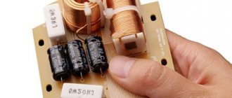
Inductors are widely used in analog and signal processing circuits. They combine with capacitors and other radio components to form special circuits that can amplify or filter signals of a specific frequency.
Inductors have a wide range of applications ranging from large inductors such as power supply chokes that, in combination with filter capacitors, eliminate residual noise and other oscillations in the power supply output, to as small inductors as those found inside integrated circuits.
Two (or more) inductors, which are connected by a single magnetic flux, form a transformer, which is the main component of circuits operating with an electrical power supply network. Transformer efficiency increases with increasing voltage frequency.
For this reason, aircraft use AC voltage with a frequency of 400 hertz instead of the usual 50 or 60 hertz, which in turn allows for significant savings in the mass of transformers used in the aircraft power supply.
Inductors are also used as energy storage devices in switching voltage stabilizers, in high-voltage electrical power transmission systems to deliberately reduce system voltage or limit short-circuit current.
Species and types
There are low-frequency and high-frequency models. Screw and spiral coils are classified into a separate category. There are also modifications that are used in radio engineering. They are suitable for protecting capacitors or resonant circuits.
Devices in radio engineering
For transformers, coils with a cascade amplifier are suitable. The last category includes variometers; the main difference is the high frequency of the oscillatory circuits. Chokes can be single or double. The inductance and power supply of the system depends on this.
Low frequency
To be included in an electrical circuit, a low-frequency inductor is used. It is designed to suppress alternating current. The formula takes into account cyclic frequency and inductance values. The devices are based on a core made of steel. It can be with or without filters.
You may be interested in Installing an RCD in an apartment
To influence the frequency, a game is played with resistance. In a DC circuit, the voltage must remain constant. Filters are used to reduce the frequency. The main problem is the small capacity. To familiarize yourself with the inductor in detail, it is worth learning more about the resonant frequency, which stands out on the operating signal circuit.
When voltage increases in the circuits, stress is placed on the frame. The DC circuit uses opaque wirewound resistors. Single-layer universal-type coils are also suitable for these purposes. Their peculiarity is the use of ferrite rods.
Low frequency coil
High frequency
The devices are manufactured with different types of winding. We are talking about a set of advantages that save in a given situation. The scope of application of the elements is wide, taking into account the significant modulation frequency. In this way, it is possible to combat the increased resistance of metals. The coils have a core.
The main task is modulation of the generator frequency. It occurs due to signal amplification, and the process can be monitored by connecting an oscilloscope. Many high-frequency coils are not stable because they use a ceramic frame. It has a short shelf life, plus they are susceptible to high humidity.
Interesting! Modern products are made of aluminum and are compact.
Electricians are familiar with circuit and non-circuit modifications of high frequency. Depending on the winding, the stability of the electrical parameters is taken into account. High frequency models may use magnets and wires. We are talking about powder materials made from dielectrics.
The manufacturing process is associated with the cold pressing method. Inductive sensors differ in their protection. At enterprises, elements can be immersed in a solution or threaded into a tube. This is done to avoid short circuits. Global manufacturers solve the problem by using a secondary coil.
High frequency coil
The models have significant resistance and have a problem with electrolyte concentration. This changes the properties of the inductor. The conductivity of the solution decreases and the frequency of the electromagnetic field increases.