Characteristics of GM-70
Typical operating parameters
- Type of electrode system - triode
- Heat - direct
- Base - special
- Decoration: glass
- Lamp anodes were made of copper, steel or graphite.
The tube was often used in short-wave amplitude modulation radio transmitters to control the level of the output signal by varying the voltage at the anode of the output generator tube. It was also used in broadcast amplifiers, for example TU-5-3.
Among radio amateurs, the GM-70 has found wide use in homemade designs of low-frequency amplifiers intended for high-quality sound reproduction. The advantages of the lamp are low internal resistance, high output power, and linear current-voltage characteristics. It is capable of delivering up to 15 W in class A, up to 40 W in class A2 and up to 170 W in class B2.
The GM-70 is called the queen of triodes by radio amateurs for its high power and linearity of characteristics, as well as the beauty of its appearance.
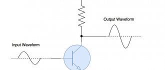
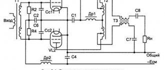
Circuit diagram of an audio amplifier based on a GM70 radio tube
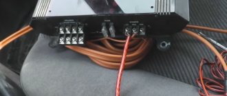
The anode supply is common to both channels, the filament and negative bias supply are different for each channel. Here is a list of radio elements for one channel:
R1 – 1k R2 – 330K R3 – 250 R4 – 33k 10 W R5 – 4k 10 W R6 – 11k 20 W R7 – 1k 5 W R8 – 380K 5 W R9 – select for 100 mA R10 – 470 5 W R11 – 160K 2 W R 12 – 51 10 W R13 – 51 10 W R14 – select for 200 mA P1 – potentiometer 100 Ohm 25 W
C1 – 0.1uF 600V C2 – 50uF 600V C3 – 0.22uF 1000V C4 – 10uF min. 160V C5 – 10uF min. 160V C6-C14 – 680nF 1200V
L2 – Throttle BCP-13 GC NI
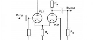
Amplifier circuit for GM-70
In this circuit, the cathodes of the driver tubes are placed on the ground, therefore there is a fixed bias. A 6P3S in triode connection works as an output driver. The main power filter capacitors are located in the power supply itself. The amplifier blocks contain only a few non-polar capacitors of small capacity to power the input and driver stages.
Reviews from audiophiles: GM-70 is the breadth and scale of sound. This tube can be used to create a decent amplifier with an output power of more than 20 W. The sound is very powerful and a bit straightforward. The small nuances of the musical work are somewhat suppressed by this power and pressure, and I would like a more delicate sound.
History develops in a spiral. It's time to create a tube amplifier. It turned out to be not at all easy. It was necessary to turn off the postulates of the transistor vision of the world within ourselves, to rebuild everything under the tube one. There is practically nowhere to get knowledge: books on lamps have mostly gone to the trash. I had to dig up the internet. It took about a year to find knowledge and an acceptable pattern for repetition.At first I wanted to make an A class with 2 6P3S in parallel, but rejected this scheme. I thought 6 watts would not be enough. Then I came across Manakov’s 6E5P circuit - GM 70 23 watt A class. For eyes . Difficulties began where I did not expect. 1 where to find IRON. My feet took me to the oldest cinema in the city. It turned out that the smoking room was alive. In the basement the LOMO U 013 tube amplifiers were lying and waiting for me (inscription on the nameplate). 2 clock on 6Р3С. The unshaven electrician gave me four of them and a whole box of 5Ts3S. My breath was spiraling with happiness. The iron was twisted from there to 30 kg. The manufactured output trance passed 35 kHz without decay. I made it from two Ш plates placed on top of each other, I borrowed the idea from Demchenko. I soaked the coils with an ointment made from wax welded with transformer oil (I came up with this myself). The cross section of the iron is 18 cm square. weight 7.5 kg. Look here:
The next problem is the socket under the GM-ku - it does not exist and is not expected. I solved it in my own way: a flange was machined from stainless steel in which the skirt of the lamp is fixed with a screw-pin,
the flange itself is attached to the top panel of the case, and the contacts are removed from a powerful military connector and brought to the required diameter with a drill.
As I gained knowledge in tube science, I decided that the coupling capacitor was worse than the coupling trans. Then I came across A. Shalin’s diagram, kindly posted for everyone to see:
And I must say, it’s very laconic. I found from the network about 20 circuits on GM 70 and 211 lamps, but I immediately liked Shalin’s circuit, I decided to stop with it, contacted him, asked how the interstage trans works, and made it according to his recommendations. For which I thank him very much. From theatrical hardware, the -3dB band turned out to be 8Hz 38kHz:
The GM 70 filament is powered by a torus. In an electrical goods store you can find tori for illuminating display cases with 12V halogen lamps
in this 200 W trance, 12 V is wound in 2 wires. Minimal alteration and you have 20V with an ideal midpoint.
The anode GM70 is powered by the TS180, can you photograph it? It was made according to the doubling scheme on 5Ts3S. For each kenotron there is a capacity of 20 microfarads * 500V, extracted from those amplifiers and then 2 capacities in parallel
choke 10 Gn 12.5 cm of iron is almost half the output and the main capacitance MBGV is 200 μF * 1000 V. The reference book on containers says that it works well in pulse mode, which was our preference in choosing it. Actually, I stole this food from Demchenko again, in his “ongaki” scheme. Although you can’t stupidly repeat it, one kenotron is connected incorrectly. The grid bias here is all just 4 fast diodes, a P filter, although there are already electrolytes and not BG, there is nowhere to get them. But at least the shunted K40U9. and the throttle is the simplest from the TV set 5-0.08. With a quality mark. And also a resistive divider to adjust the mixing. Everything seems to be okay with GM nutrition.
Now 6E5P is powered by its own transformer for iron, similar to the interstage one, it’s even a pity to waste it there, it’s too good. anode according to the scheme as a grid one for GM 70. Heat with a midpoint. Everything is simple here. How many diagrams had to be revised to simply say this.
The hard stuff is over. Although there is one more trance. I'll tell you about it later.
Weight with the housing per channel gained 28 kg. I would recommend starting to build an amplifier with the chassis. Because installation on plywood often ends there, unless electrical injuries happen to loved ones.
Here's what it looks like before painting.
The output trans was placed on top of the amplifier. It is closed with a large stainless steel cylinder (from household goods - a container for food) under a small separating trans (a mug with a torn off handle) and another MBGV, to which I soldered 2 ears for fastening.
I made the volume using an autotransformer. The hardware, if you can call it that, was taken from a Kip amplifier with 2 tubes.
it turned out to be a permalloy and skipped the band linearly up to 55 kHz, and my generator does not generate any further. P iron 1.2 cm rod type.
There are 5500 turns of 0.1 on 2 coils with taps for 12 switch positions. 35 H winding inductance. In our city there is a certification center; in the laboratory there is a device that measures elephant Hn, so here’s a chocolate bar and there. Measure. This is a hint where to find the L meter.
Turning on and tuning the assembled ULF
The first start must be made in the following order:
- turn on the power lamp and, if necessary, set the appropriate filament voltage - 20 V for GM70.
- connect the input lamps, check the filament value is approximately 6.3 - 6.5 V.
- Set the voltage in the negative power supply to about 100 V.
- The anode power supply has approximately 1000 V at load.
Current values for 6S19P – 20 mA and for GM70 – 80 mA.
The cost of building the amplifier is almost 100,000 rubles, the time is 1 year. The price of the GM-70 lamp is about 2000 rubles, 6S19P is about 200, 6S3P is also about 200 rubles. Total weight about 90 kg. The amplifier operates stably for many months, the currents are also stable, which is extremely important. We recommend this design because the sound really compensates for the time spent.
A resistor, for example 1 MΩ, must be placed between the bias potentiometers and the terminal connected to the negative voltage. By adding such a resistor, the lamp will be blocked in an emergency, and nothing will happen to it.
Compared to factory tube ULFs, the resulting device represents a significantly higher level of sound quality. After all, if someone listens to classical music, jazz, instrumentals, loves good vocals, good-sounding classical guitar, it is difficult to find something better than triodes. Useful files for those who want to repeat the design in the archive. Project author Dariusz , email
- SUPER QUALITY 10 W AMPLIFIER
- NUTUBE 6P1 TUBE AMPLIFIER
- SE TUBE AMPLIFIER
- ULF WITH CATHODE FEEDBACK
Sergei Klimanski
Again I set out to complete the amplifier I had started earlier. True, the circuit had to be changed, because in the selected steel case from Dun Mei https://www.vt4c.com/shop/program/main.php?cat_id=1&group_id=2 there was no place for interstage UIS transformers so that they would not pick up interference from power supply circuits and from network transformers, the total rated power of which is 800 W (400 W anode and 400 W filament). This time I took the classic Dynaco ST-70 circuit https://diyaudioprojects.com/Schematics/Dynaco-ST70-Tube-Amp-Schematic.htm as the basis for the pre-amplification. The board purchased on e-Way was assembled according to the standard design, only instead of 7199 there is a 6GH8A installation, which has the same pinout as the 6F1P. Also suitable here are 6EA8, 6U8 (ECF82). The only thing that was changed was the values of the correction circuits and the OOS resistor was set to 10 K instead of 1K, which led to a decrease in the OOS value to 6 dB. The 6F1P filament is powered by rectified current; unfortunately, no tricks made it possible to power it directly from the 6.3 V winding of the transformer. And from the power divider of the first stage, approximately +100 Volts are supplied to the filament to eliminate the background.
The driver stage is assembled on 6Н12С (6BL7) with a quiescent current of 15 mA. The 6N12S filament is powered by an alternator, one of the terminals is grounded. Without changing the ratings of the parts, you can install 6N8S here, but then the cascade is reduced to 8 - 10 mA, which is not enough for the GM-70.
The output stage operates in class AB with a quiescent current of 50 mA, the anode voltage is slightly more than 1 kV, the bias is fixed at about minus 110 volts, the current of each lamp is adjusted separately. Despite the push-pull, the filaments of the output lamps are powered by a constant voltage, since it is very difficult to completely eliminate the background when powered by alternating voltage. As an experiment, A-431S transformers with Raa = 4300 Ohms were installed as output transformers, which is perhaps more consistent with the internal resistance of the GM-70 (about 1200 Ohms) than was the case in the earlier design, especially since the circuit now has an OOS .
The power supply is basically left unchanged - these are toroidal transformers from ANTEK with a diode rectifier, only it is supplemented with a bias supply circuit to the GM-70 - a small-sized printed transformer with a power of 2 W is used as a network for this circuit. The scheme is still preliminary, adjustments are possible.
Measurements first. Bandwidth at minus 1 dB from 7 Hz to 39 kHz. Unfortunately, the spectrum is dominated by the third harmonic with the second harmonic practically absent; at 5 V at the output, the third harmonic is minus 46 dB from the first, at 15 V at the output – minus 32. Apparently, because of this, the sound is quite sharp, and if more or less acceptable at low volumes, but becomes unpleasant at high volumes. We'll have to modify the diagram.
The modification was reduced to converting the pentode part of the 6F1P into a triode. After this, the sound improved, and what’s interesting is that I liked the sound of the ECF82 Telefunken and 6GH8A RCA less than the 6F1P - the Soviet light bulb (made in ’66) has a less noisy midrange and a richer bass register. During three hours of operation, the amplifier case warmed up to 40 - 50 degrees in places, and the output transformers also became warm, but this did not affect the operation of the amplifier in any way. What else I liked is that after converting the pentode to a triode, the noise level dropped to 2 mV - a meter away from a speaker with a sensitivity of 98 dB, the background is not audible at all. Measured output power is 42 watts. Another interesting observation. I replaced the cathode resistor R4 with a 1.2K AllenBradley and became convinced that the carbon resistors were noisy - a clearly audible white noise appeared in the speakers, which disappeared after replacing the AB with a regular metal oxide one (only later I installed a blocking electrolyte). The scheme after revision is also, apparently, not final. For details. Potentiometer VR3 VR4 is a dual linear one; it sets the overall bias level for both lamps in the channel, and potentiometer VR5 balances the anode current of the lamps in the pair. Anode resistors 6Н12С – Kivame, interstage capacitors – MKT ERO.
Today, May 14, 2012, I finally managed to lower the background level to 0.8 mV at 6.8 Ohms and listen to the assembled amplifier on good acoustics. No fan yet, although I have planned to install one on the rear panel of the amplifier. Over 4 hours of continuous operation, the temperature inside the amplifier case stabilized and did not exceed 64 degrees. Unfortunately, the output transformers got very hot (the black ones are heated by as many as four GM70 lamps with their radiation!), so we will have to install a mirror screen.
Equipment. Denon CD player, recently purchased DAC from Audio Instrument with a tube-transformer output, van den Hul interconnect cables, speakers - Visaton B200 full-range speakers with a 1/4 wave resonator bass design, custom speaker cables from Custom Hifi Cables Ltd UK. Material – 1. Marc Kohn gold disc, 2. Adriano Chelentano “L’Animale”, 2008, 3. Ian Clarke, “Within” Diva Music studios, UK, 2005. The first thing that caught my eye (or rather, my ears) – It’s that the triode connection of the first stage on the 6F1P still sounds inexpressive and I returned to the original circuit with a pentode connection, exactly like Dynaco’s. At the first listening, the drivers were 6N8S MELZ, 6F1P - Svetlana 1966. The GM ones for now are all used, bought on the market; although there are new lamps, I haven’t installed them yet.
I've heard a lot of comments about the sound of the GM-70, opinions are very different, from rejection like the “straightforward” sound or “were you sitting in the front row in the concert hall?” to delights like “powerful”, “killer”. But what I heard was a revelation for me. I must admit that my scale for assessing the sound of an amplifier turned out to be too narrow and, unfortunately, it is difficult for me to adequately describe what I heard; I need to expand my scope of musical perception. With an absolutely impeccable tonal balance, good stage and excellent dynamics, the amplifier revealed its ability to perfectly convey the emotional coloring of music at low volumes; I have never heard such a flute (disc 3) on any amplifier before. Yes, yes, dear reader - a flute - and on the GM-70! If someone had previously told me that I would be listening to a flute solo performed by a two-stroke on a GM-70, I would have only laughed in response... I called my wife and all evening we listened and listened as if spellbound - you can’t fool a woman - it is the excellent transmission of the emotional part of the music that attracts our fair half... About the bass and treble, detail, etc. I'm not talking anymore. I admit, of course, the SE will have greater detail in conveying nuances on the 2A3. I assembled four 2A3 amplifiers, but what I couldn’t get from them was bass dynamics and that very emotional transmission of musical images. It's all there. One of my acquaintances, a car enthusiast who knows his subject not from advertising brochures, once admitted that a real passenger car starts with a 3-liter engine. So I came up with an analogy - that maybe a real tube amplifier starts at 40 watts...? There is an opinion, which by the way is absolutely correct, that even with the help of a 3-watt single-cycle you can get a loud noise in the room that is unbearable for people. But the point is that the amplifier's job is to create musical images, not noise. And this is where you need a power reserve to correctly reproduce the entire dynamic range of the recording. At least, this is how I explained what I heard to myself, because the diagram is standard and there are no special details in it. If we estimate the cost, then this amplifier cost me about 700 dollars, 80% of which were transformers and housing. For those who have golden hands and who wind trances themselves, the cost of an amplifier will be completely ridiculous. As a piece of advice, it would still be good to take more Raa output trances; after all, distortion is high at high volumes.
Added May 15. Yesterday I installed a 12 volt 80 mm computer fan on the rear panel; with its continuous operation, the temperature inside the case did not rise above 26 degrees in 4 hours. True, it is still a little noisy and I mocked up a simple fan control circuit that turns it off during pauses and when the average signal level is low. Works great. The response threshold is set by potentiometer VR1. There is only a small modification left - to install a stereo balance control, while it is not there yet. After finalizing the placement of conductors inside the case and after installing a grounded protective grill on the pre-amplifier board on the 6F1P (this grill also protects the board from GM70 radiation), the background level dropped to a level of 0.3 mV and is no longer completely audible on acoustics with a sensitivity of 95 dB. Photos of the insides of the box will be later, when I complete all the installation of imperfections.
Towards the end, a couple of photos of 6F1P lamps, one of them is Svetlana, the other is presumably an Eagle with its old logo.
Again I want to thank Sergei Glazunov, this time for the wonderful DAC, I really liked this product for its musicality and very accurate transmission of the material.
Transformers for amplifier
- Output transformers SE100-1 7k/8/4 Ohm cores EI120/73
- Two inductance coils 5H/500mA core Ei84/42
- Other choke 10H Ei54 core 100m/18
The output transformers are not homemade, but ready-made. Their main parameters:
- Ra – 7 k
- L – 30 H / 120 Hz
- R (dc) – 170 Ohm
- Imax – 0.2 A
- Weight about 7 kg
Transformer frequency range:
- 6 Hz – 53 kHz -3dB Р = 1W 8R
- 6 Hz – 51 kHz -3dB Р = 1W 4R
- 14 Hz – 28 kHz -0.5dB Р = 1W 8R
- 14 Hz – 25 kHz -0.5dB Р = 1W 4R
- 18 Hz – 38 kHz -3dB Р = 30W 8R
- 18 Hz – 37 kHz -3dB P = 30W 4R
- 25 Hz – 25 kHz -0.5dB Р = 30W 8R
- 25 Hz – 22 kHz -0.5dB Р = 30W 4R