Sensor for automatic activation of UMZCH
AF power amplifiers are now usually made on UMZCH integrated circuits. This is very convenient because it allows you to obtain a fairly high-quality Hi-Fi amplifier relatively inexpensively and without significant labor costs. In addition, the UMZCH microcircuit, in addition to the signal amplification function, has other useful functions, for example, an output that switches it to an energy-saving mode. In this case, there is no need for a powerful power switch that turns off the UMZCH completely, but it is enough just to change the voltage at the corresponding pin of the microcircuit. Thus, it is possible to organize control of turning the UMZCH on and off automatically, due to the signal source. In this case, you need to make a sensor for the presence of an input signal and additionally attach a timer to it. A timer is needed so that the UMZCH does not turn off during breaks between programs or pauses in a piece of music. In this case, it is necessary that the amplifier turns on immediately after the signal arrives at the input, without delay.
The schematic diagram of the sensor is shown in the figure. The input resistance of the sensor is 100 kOhm; usually the input resistance of an integral UMZCH is much lower. But, if necessary, the input resistance of the sensor can be increased by increasing the resistance of resistors R1 and R2. These resistors must be of the same resistance, since they create a bias voltage at the op-amp input equal to half the supply voltage. This is necessary for the op-amp to operate from a single-pole power supply. The sensor input is connected parallel to the input of one of the stereo channels of the UMZCH. During the absence of a signal, there is no alternating voltage at output A1, transistor VT1 is closed and the voltage at its collector is equal to logical zero. In this case, the voltage at the output of logic element D1.3 is a logical unit. This should correspond to the off state of the UMZCH.
As soon as a signal arrives at the input of the UMZCH, it also arrives at the input of op-amp A1. The op-amp amplifies this signal and can even be limited (it doesn’t matter), the main thing is that it reaches a level at which transistor VT1 begins to open in switch mode. In this case, there will be pulses of arbitrary shape and frequency on its collector, the very first of which will trigger a monostable on logic elements D1.1 and D1.2. A logical one will appear at output D1.4 for a time not less than the time constant of circuit R7-C5. With this voltage, through resistor R8 and diode VD1, capacitor C7 will relatively quickly be charged to a logical one voltage. The output of element D1.3 is zero, which turns the UMZCH into operating mode.
During breaks between programs, pauses in a piece of music, there is no alternating voltage at output A1, transistor VT1 is closed and the voltage at its collector is logical zero. Accordingly, the output D1.1 will be a logical one, and the output D1.4 will be zero. But this does not lead to the UMZCH turning off immediately, because in this mode, when output D1.4 is zero, capacitor C7 is discharged mainly through resistor R9 and its own leakage, which takes about a minute. Therefore, the UMZCH turns off only a minute after the signal source has been turned off.
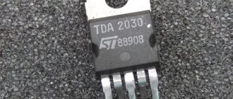
The K561LE5 digital microcircuit can be replaced with imported analogues of type 4001. The operational amplifier type NE5534N can be replaced with almost any general-purpose op-amp, for example, with TL071, K140UD6 or another.
Setting up. By adjusting resistance R3, you need to set the gain A1 at a level at which the sensitivity of the sensor is sufficient to reliably turn on the UMZCH even with a very small signal, but the circuit does not respond to noise or interference in the preamplifier.
Author: Lyzhin R.
Single-ended amplifier Semigor in economical class A
The idea to assemble an amplifier in “economical” class A appeared in connection with the approach of summer. Honest class A is good for everything, except for the large amount of heat generated, which warms the listening room and the listener’s body itself. All this leads to increased consumption of electricity and beer.
Rice. 1. Pseudo-single-ended output stage in economy class A
Figure 1 shows a simplified circuit diagram of the output stage. I’ll say right away that I agree that everything has already been invented, but I haven’t come across such a specific scheme. If it has another author, write to me and I will provide a link.
The idea is standard. When the positive half-wave of the signal is amplified, T2 and T4 are closed, and T3 operates as a normal emitter follower, all of whose current flows to the load. When the negative half-wave increases, T2 controls the current T4 in such a way that the current through R2 = const and T3 remains in the active mode. Below is an approximate calculation of the circuit.
We assume that the current transfer coefficients of the transistors are significantly greater than 1, then:
Ik = Ie = Ib • h , where
Ik – collector current;
Ie – emitter current;
Ib – base current;
h – current transfer coefficient of the transistor.
If transistors T1 and T2 are of the same type and are in the same temperature conditions (on the same radiator), we can assume with reasonable accuracy that:
I1 • R1 = I3 • R2.
The following relations are also valid:
I3 = I2 + I4
I5 = I4 – In = I2 • h3 , where h3 is the coefficient. current transmission T3.
This implies:
I4 = [I1 • h3 • (R1/R2) – In] / (h3 – 1)
or, taking into account the fact that h3 >> 1 :
I4 = I1 • (R1 / R2) – Iн / h3
When the load current is 0, the quiescent current does not depend on h3 and is determined by the expression:
I4 = I5 = I1 • (R1 / R2)
The maximum current through the load when amplifying the negative half-wave of the signal can be found from the condition: I4 = 0, then:
In max = I1 • h3 • (R1 / R2)
Rice. 2
To practically test the idea, I assembled a circuit, which is shown in Fig. 2. This is a working prototype that I hope to finalize over time.
- The input stage is a transistor SRPP.
- A 22 Ohm variable resistor sets the quiescent current to 190 mA.
- The KD213 diode will limit the voltage drop across the current sensor (1 Ohm resistor).
- An additional KT626 transistor, connected to a common base, increases the speed of the control circuit and reduces the power dissipated on the upper KT626 transistor.
- The coil in the emitter of the lower 2T908 transistor ensures the stability of the circuit.
Author: Igor Semynin , based on materials: semigor2.narod.ru
Design
This is how it was planned to use the voltage from the power supply:
- +36V, -36V - power amplifiers on TDA7250
- 22V - switch-on delay and speaker protection circuits
- 12V - electronic volume controls, stereo processors, output power indicators, thermal control circuits, fans, backlighting;
- 14V - electronic tone controls.
- 5V - temperature indicators, microcontroller, digital control panel.
The voltage stabilizer chips and transistors were mounted on small heatsinks that I removed from non-working computer power supplies. The cases were attached to the radiators through insulating gaskets.
The printed circuit board was made of two parts, each of which contains a bipolar rectifier for the UMZCH circuit and the required set of voltage stabilizers.
Rice. 4. One half of the power supply board.
Rice. 5. The other half of the power supply board.
Rice. 6. Ready-made power supply components for a homemade power amplifier.
Later, during debugging, I came to the conclusion that it would be much more convenient to make voltage stabilizers on separate boards. Nevertheless, the “all on one board” option is also not bad and is convenient in its own way.
Also, the rectifier for the UMZCH (diagram in Figure 2) can be assembled by mounted mounting, and the stabilizer circuits (Figure 3) in the required quantity can be assembled on separate printed circuit boards.
The connection of the electronic components of the rectifier is shown in Figure 7.
Rice. 7. Connection diagram for assembling a bipolar rectifier -36V + 36V using wall-mounted installation.
Connections must be made using thick insulated copper conductors.
A diode bridge with 1000pF capacitors can be placed separately on the radiator. Installation of powerful KD213 diodes (tablets) on one common radiator must be done through insulating thermal pads (thermal rubber or mica), since one of the diode terminals has contact with its metal lining!
For the filtering circuit (electrolytic capacitors of 10,000 μF, resistors and ceramic capacitors of 0.1-0.33 μF), you can quickly assemble a small panel - a printed circuit board (Figure 8).
Rice. 8. An example of a panel with slots made of fiberglass for mounting smoothing rectifier filters.
To make such a panel you will need a rectangular piece of fiberglass. Using a homemade cutter (Figure 9), made from a hacksaw blade for metal, we cut the copper foil along its entire length, then cut one of the resulting parts perpendicularly in half.
Rice. 9. A homemade cutter made from a hacksaw blade, made on a sharpening machine.
After this, we mark and drill holes for the parts and fastenings, clean the copper surface with fine sandpaper and tin it using flux and solder. We solder the parts and connect them to the circuit.
Legends and myths
If you type the phrase “buy a voltage stabilizer” in the search bar on your PC, you will get a kilometer-long list of sellers who will assure that their super-precise devices are necessary for all users without exception. In most cases, prices range from five to six figures.
But upon deeper analysis, it turns out that not everything is so simple.
- Precise adjustment of the voltage parameter is a good marketing ploy for the manufacturers of these same stabilizers. They often indicate ranges of ±2, 4, 6% and even 0.5% and sell devices at exorbitant prices. In reality, for the vast majority of equipment, a real voltage of 220-230 V ± 10% is sufficient. Almost all equipment has a margin of “strength”; in extreme cases, you can familiarize yourself with the recommendations of the audio equipment manufacturer from the device’s passport;
- All stabilizers improve sound quality - this is not true, moreover, a stabilizer can worsen the sound signal. This is the problem with many electronic stabilizers created on the basis of thyristors and triacs. The reasons are radio interference emitted by such semiconductors. This fact has been proven many times when connecting an oscilloscope to the output of stabilizers of this type.
Conclusion
Relay and electromechanical (servo-drive) type stabilizers do not have any noticeable effect on sound quality. Their main task is to ensure normal operation of all elements of the user’s equipment and protect them from premature failure. It is recommended to purchase a voltage stabilizer for audio equipment only if it is reliably known that the voltage in the network is unstable and differs from the standards specified by the audio system manufacturer.
To accurately determine the average voltage value, measurements should be taken at different times of the day, on weekdays, weekends and holidays.
When choosing a voltage stabilizer, you should be guided by the following considerations:
- The power of the device must be no less than that of electricity consumers. Optimally - with a 3-5 fold margin;
- choose either relay or servo. Electronic (triac, thyristor or double conversion) can interfere with sensitive equipment, especially budget models whose switching moment is not tied to the moment the current crosses zero;
- A relay stabilizer is a cheap device, but since the relay contacts constantly burn out, sometimes you will have to repair it (replace the relay).
Summarizing all of the above, we conclude that the optimal stabilizer for acoustics is a servo drive one. It does not distort the output signal, does not create interference, makes adjustments with a high degree of accuracy and is not very expensive.