About power supplies
At least two articles have already been written about the power supply for the amplifier: Power supply for TDA7293 and TDA7294 and Power supply for the amplifier - circuit and operation. The second of them examines in detail the structure of the power supply and the operation of its components. The power supply circuits that are described in the articles are actually excellent, they work well, and it is according to them that the vast majority of power supplies are built, both in homemade and industrial equipment. What will happen here? Here I want to give a practical circuit for a “flawless” power supply for an amplifier.
“Impeccable” does not mean “the most perfect” or “the best.” And not only because for some, “the best” is one with a built-in coffee machine. This power supply optimally (and not at all maximally!) eliminates all errors, interference and instabilities. So, to get power quality, not ideal, but sufficient for excellent operation of almost any amplifier.
A typical power supply circuit is given in the article Amplifier Power Supply and shown in Fig. 1. This is an excellent power supply, implemented in a similar form in a huge number of devices. The transformer divides it into two parts: to the left of the transformer is the high-voltage part, connected to the AC network, and to the right is the low-voltage part, connected to the amplifier.
Rice. 1. Amplifier power supply diagram.
The high-voltage part of the power supply must contain a fuse and a power switch. It is also highly advisable to use a surge protector. Typically, using a noise suppression capacitor gives fairly good results. Moreover, I highly recommend using it.
A more complex filter can be used, but with caution - depending on the filter circuit and the presence or absence of grounding of the case, a complex “correct” filter can create problems: the case may be under mains voltage when communicating through Y-capacitors. In addition, it is necessary to correctly estimate the current consumed by the amplifier from the network, otherwise the filter will be overloaded with current and its efficiency will be significantly reduced. In addition, ready-made assembled filters are quite expensive, and when assembling a filter from separate components, there is a chance of making mistakes in their correct use.
We'll talk about good network filters another time. For now, we’ll make do with one noise-suppressing capacitor, which is usually quite sufficient.
Therefore, let's deal with the part that is located to the right of the transformer - the low-voltage one. The work of this part is more important.
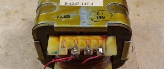
↑ Transformer
The standard frame of the selected standard size has 10 pins, 5 on each side. I ran it like this:
- 1-2: primary winding - 86 turns with PEV-2 wire 0.335 mm
- 3-4-5: self-supply winding with a midpoint of 4-2×15 turns PEV-2 0.335 mm
- 6-7-8: winding of a bipolar source, midpoint 7-2×15 turns PEV-2 0.335 mm
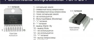
- 9-10: anode winding - 186 turns (or 200 for the stabilizer) PEV-2, 0.112 mm
- Separate leads: filament winding - 6 turns PEV-2, 0.6 mm
The winding order is straight as indicated here. Insulation must be laid between each winding (or better yet, each layer). For example, I use this self-adhesive polyester tape:
I highly recommend her. Well, or varnished fabric. You can use fluoroplastic (aka Teflon) or FUM tape with caution, because fluoroplastic is fluid and with strong winding force it will simply spread between the turns. And with weak force there will be no room left for the windings themselves. In general, we focus on polyester or varnished fabric.
The filament winding is wound on top of all the windings, but the ends are made longer and not down, but up. After this, the transformer is assembled and fastened with staples.
Traditionally, it is customary to divide the primary winding into 2 parts, and wind one part first, and the second last, after the other windings. In general, this is true, this reduces leakage inductance and increases magnetic coupling. But this is not our choice.
It's all about the glow of the lamps - at startup they are cold and require a very high starting current. Rectifier diodes and switches may not understand such greyhound jokes and explode. Therefore, it is better to wind the primary winding first and not divide it. The leakage inductance will increase, but the magnetic coupling will weaken and the current-voltage characteristic will become steeper. As a result, at the start, during a sharp increase in current, there will not be an equally sharp increase in the current in the switches.
Then make 1 short-circuited turn of copper foil on top of the windings and core, i.e. This screen is made not just over the windings, but over the entire transformer! It would be useful to later connect this screen to the common bus of secondary circuits.
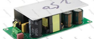
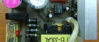
Next we deal with the conclusions: first, the ends of the windings with the conclusions are soldered, after which the transformer is soldered into the board. Then the ends of the filament winding are measured to a length sufficient to connect to two pads near the transformer (ST1 and ST2), the ends are stripped and tinned, and the ends themselves are put on with heat shrink tubing. Afterwards the ends are soldered into the board. The photo shows a transformer without a copper screen.
"Flawless" power supply for the amplifier
The circuit of a “flawless” power supply is shown in Figure 2. It is not fundamentally different from the original one shown in Figure 1. Several additional elements have been added to the circuit, which slightly improve its operation. They improve it a little, because it is impossible to greatly improve the original scheme.
Rice. 2. “Impeccable” power supply for the amplifier.
A transformer is connected to the left contacts (~, Gnd, ~), and a constant supply voltage is supplied to the amplifier from the right contacts (+, Gnd, -).
Resistors R1, R2 together with capacitors C1, C2 form two snubbers, each of which is connected to its own half-winding of the transformer. The snubber serves to suppress possible high-frequency oscillations (oscillations). Where might these fluctuations come from? The current from the transformer is consumed in short pulses, this is the work of the rectifier on a capacitive load. At the moment the rectifier diodes close, the current in the circuit decreases to zero in a fairly short time. Due to the inductance of the transformer, voltage surges may (or may not) occur, the energy of which is usually “gently” dissipated by the resistance and capacitance of the transformer windings. But sometimes, under very unfortunate circumstances, the energy stored in the inductance of the transformer (and causing voltage surges) can be dissipated in the form of high-frequency oscillations. Moreover, each half-cycle of the network voltage is accompanied by a “flare” of high-frequency oscillations. Snubber capacitors pass such oscillations to resistors, where the energy is dissipated, turning into heat. To be honest, I have never encountered such oscillations in practice. In all cases there were no conditions for their occurrence. Therefore, snubbers are a rather unnecessary element of this scheme. Most likely, there will be no work for them. What then do I use them for? But we make the best power supply for the amplifier, don't we?
Diodes VD1-VD4 form a rectifier. Why this particular one is the best, I have already written about this. The rectifier uses Schottky diodes. Not because they are more magical. And not even because they are faster. But because:
- Less voltage drops across them, which means the amplifier will receive more voltage.
- Less voltage drops across them, which means that at the same current they will heat up less than “regular” diodes.
By the way, the faster the diodes used in the rectifier, the greater the chance of shock oscillation, which has to be suppressed by snubbers.
Each of the diodes is shunted by a capacitor (C3...C6). These capacitors, like snubbers, reduce switching interference, but for each diode separately. Interestingly, the shunt capacitors form a bridge, Fig. 3. The transformer is connected to one diagonal of this bridge, and the load to the other. Therefore, with an ideal bridge balance, high-frequency interference coming from the network through the transformer does not reach the load. To do this, the capacitors must have the same capacity. But there is no need to select them by capacity. It is enough to use capacitors of the same rating. The fact is that this function is secondary: interference in the network must be suppressed even before the transformer, so a slight imbalance of the bridge caused by the scattering of capacitor capacities is not at all terrible. And the imbalance of the bridge will be small, so the interference will be suppressed quite well.
Rice. 3. Bridge of shunt capacitors.
By the way, the capacity of the shunt capacitors is many times greater than the capacity of the rectifier diodes. So capacitors make the current switching process much slower (the diode turns off quickly, but current continues to flow through the capacitor). Therefore, the “fast diode plus capacitor” system turns out to be much slower than the “regular slow diode without capacitor” system. Nevertheless, despite the “excessive slowness”, the system with a capacitor is better, which has long been known. This once again confirms the fact that myths about the good “sounding” of fast diodes in a rectifier are just myths.
Large-capacity electrolytic capacitors C7...C12 store energy and act as a power filter. They are charged by short current pulses coming from the rectifier, and give this energy to the amplifier in pauses when the voltage in the network passes through zero. If we consider their work from the other side, then these capacitors smooth out the ripple of the supply voltage. The main thing is that the amplifier receives energy from these capacitors during 90% of its operating time. So the capacitors must be of high quality. But no magical properties are required from these capacitors. It is much more important to choose and connect them correctly. We look at this below.
Film capacitors C13, C14 help electrolytic capacitors operate at high frequencies. The fact is that all capacitors have a certain maximum operating frequency, above which their properties noticeably deteriorate. And for electrolytic capacitors, this maximum operating frequency is in the audio range. That is, at higher audio frequencies, large-capacity electrolytic capacitors do not work well enough.
Selection of voltages for secondary windings
Knowing the required voltage at the output of the rectifier after the electrolytic capacitors, you can approximately calculate the required voltage at the output of the secondary winding of the transformer.
The numerical value of the direct voltage after the diode bridge and smoothing capacitors will increase by approximately 1.3..1.4 times compared to the alternating voltage supplied to the input of such a rectifier.
In my case, to power the UMZCH you need a bipolar DC voltage - 35 Volts on each arm. Accordingly, an alternating voltage must be present on each secondary winding: 35 Volts / 1.4 = ~25 Volts.
Using the same principle, I made an approximate calculation of the voltage values for the other secondary windings of the transformer.
Capacitors
A typical dependence of the impedance (impedance modulus) of an electrolytic capacitor with a capacity of 10,000 μF on frequency is shown in Figure 4 (according to the Nichicon company, I put the red dots on the graph). The dotted straight lines on the graph show the behavior of an ideal capacitor (line Xc) and an ideal inductor (line XL).
Rice. 4. Dependence of impedance (impedance modulus) of an electrolytic capacitor on frequency.
At low frequencies, the capacitor behaves “correctly”, and has the properties of a capacitor: as the frequency increases, its impedance decreases proportionally. This occurs to the left of point A in Figure 4 when the graph representing the properties of the capacitor coincides with the ideal line Xc. At higher frequencies (between points A and B), the capacitive properties of the capacitor deteriorate and its active resistance and inductance begin to affect. At point B, the capacitor is simply a resistor, but at higher frequencies (between points B and C) it is inductive. At even higher frequencies (to the right of point C), the capacitor is an inductance, where its properties coincide with the inductance line XL.
So the capacitor, whose characteristic is shown in Figure 4, works well at frequencies up to about 1 kHz, and at a frequency of 20 kHz it is practically a resistor. At higher frequencies it is an inductance. Capacitors with larger capacitances have an even lower maximum operating frequency.
In fact, not everything is as bad as it seems. Even at these high frequencies, the capacitor is able to store and release energy. That is, he works and does his job. But the fact that the capacitor exhibits the properties of inductance can cause unstable operation of the amplifier. Sometimes high-frequency oscillations occur in amplifiers (amplifiers self-excite) due to the inductive nature of the power supply circuit. Therefore, film capacitors of sufficiently large capacity are connected in parallel with electrolytic capacitors. They have a much higher maximum operating frequency and maintain capacitive operation in the audio and ultrasonic ranges, compensating for the inductive nature of electrolytic capacitors.
To be honest, film capacitors are not needed in this place. Inside the amplifier's power supply, which is made as a separate unit, additional film capacitors are practically of no use. Because the amplifier is connected to the power supply using a cable. The resistance and inductance of the cable “eat up” the entire capacitive component created by film capacitors. So the benefit of capacitors C13 and C14 is very small. But they don't do any harm. Such capacitors simply need to be installed on the amplifier board near the output transistors. In that place they work well, and without such capacitors installed on the amplifier board, it is almost impossible to obtain high sound quality. In the absence or insufficient capacity of these film capacitors on the amplifier board, high-frequency oscillations (oscillations) occur in the amplifiers. But since there is no harm from film capacitors, let them bring at least a little benefit. Ultimately, they will help suppress the high-frequency interference that passes through all our filters. With film capacitors, such interference has no chance. It is important that installing such capacitors on a printed circuit board does not worsen the performance of the power supply - so that the resistance and inductance of the conductors does not increase.
This amplifier power supply contains three pairs of electrolytic capacitors. How many pairs of capacitors should there be? When connected in parallel, the capacitances of the capacitors are summed up. Three 10,000 µF capacitors connected in parallel have an equivalent capacitance of 30,000 µF. Is it possible to use one capacitor with a capacity of 30,000 microfarads instead of these three capacitors? Can! Why didn't I do that? There are several reasons:
- high-capacity capacitors are scarce and expensive;
- high-capacity capacitors have large dimensions, so it is not always convenient to place them in the case;
- For the capacitor to operate most efficiently, its actual physical connection (the connection shown in the circuit diagram is fictitious) must be correct. Large capacitors are usually located outside the printed circuit board, and are connected by wires. In this case, it is more difficult to ensure correct connection, Fig. 5. And the resistance of the connecting wires will be greater.
Rice. 5. Correct connection of capacitors.
How many pairs of capacitors can you use? Usually from one to four or five. But most often it’s two or three. In this case, the design of the power supply is most convenient. By the way, using several capacitors of smaller capacity instead of one large one can be a good solution also because the smaller the capacitor’s capacity, the better its high-frequency properties (see Fig. 4).
↑ Assembly Features
The entire structure is located on a board measuring 160 mm x 92 mm. You need to start with the SMD parts on the bottom side of the board, because after installing the lead parts it will become difficult to solder:
Next, the output parts are installed.
It is advisable to install a small radiator on the integrated stabilizer IC2. The same radiator is a must
install on transistor Q3 if there is a high-voltage stabilizer.
Integrated stabilizers IC3 and IC4 can be installed on a piece of L-shaped aluminum profile, which should rise slightly above the filter capacitors. The same applies to diodes D20, D28, D29 and D30 in TO-220F packages.
Don't forget the jumper wires! On the board drawing they are indicated in red, supposedly on the top layer of metal. But our payment is one-sided.
Capacitor array
There is an opinion that if you use an array of capacitors - several dozen small capacitors connected in parallel, the result will be an equivalent capacitor with good high-frequency properties. This is wrong. The inductance and active resistance of the installation will be too high, and will destroy all the benefits of such a solution. I showed this in the article Capacitor Array - Myths and Reality. There is another option for including an array of capacitors, I will definitely consider it a little later and publish the results.
You can also find recommendations to connect an electrolytic capacitor of small capacity, about 100...220 µF, in parallel with the “large” capacitors. Such a capacitor does not lose its properties up to frequencies of 10...20 kHz. But this is unnecessary. One small capacitor, unable to deliver any significant current, will not bring any benefit. It will only complicate the design of the board, as a result of which the inductance and active resistance of the installation will most likely increase. The operation of such a capacitor is similar to that of a film capacitor, but the film capacitor has a much higher frequency.
Sometimes snubbers are also connected to the DC output circuit (in parallel with the filter capacitors). For example, a similar solution is in the Application Note 1849 manual from National Semiconductor. In fact, they are not necessary either.
- For high-frequency oscillations to occur at this point in the circuit, something fantastic must happen.
- Snubbers serve to remove high-frequency energy. When an amplifier is connected to the power supply, it takes away so much energy that no oscillations will occur.
- Electrolytic capacitors have a fairly high internal resistance (ESR), which effectively dissipates the energy of these possible vibrations.
So, our circuit contains both necessary and simply useful capacitors; we have abandoned the useless ones.
Other components and connection to the body
Resistors R3 and R4 serve to completely discharge the filter capacitors when the power is turned off. It is quite possible to do without them. The need to discharge filter capacitors is not urgent, but there are some reasons to do so. It would take quite a long time to describe them, so I will refrain. I recommend using discharge resistors, although not very strongly, and if you don’t want to, don’t use it. Keep in mind that at idle, when nothing is connected to the power supply, the duration of complete discharge of the filter capacitors (with the element ratings indicated in the diagram) is about one hour.
LEDs are used as indicators. The current through the LEDs is pre-selected to be very small, and the brightness of their glow is low. These LEDs are not installed on the front panel of the amplifier to indicate power, but on the power supply circuit board. Their purpose is to show you that everything is okay, everything is working. But if you want, these LEDs can be installed on the front panel. Then the current through them should be increased by reducing the resistance of resistors R5 and R6 by approximately half.
Resistor R7 connects the circuit ground to the amplifier body.
Important! The circuit ground must be connected to the amplifier case at only one point! All other elements connected to circuit ground must be isolated from the chassis.
And it makes sense if this point is located in the power supply. But the connection is not made directly, but through a small resistance resistor. The galvanic connection is preserved, and the resistor itself acts as a fuse. In case of a short circuit to the housing it:
- limits current;
- burns out and breaks the short circuit.
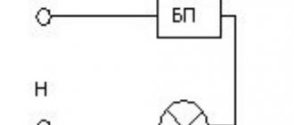
If your electrical network has real high-quality grounding, and the sockets are equipped with a third contact actually connected to the ground, then it is recommended to ground the amplifier case, as shown in Fig. 6. Both resistors are 0.125 W.
Rice. 6. Grounding.
But such a connection can only be made if you are confident in the quality of the grounding. Otherwise, leave the middle pin of the network connector not connected anywhere.
It is forbidden to connect the amplifier housing to other network wires except grounding!
Separate meals?
Sometimes you can hear that a high-quality amplifier should have separate power supply - each of the stereo channels should be powered from a separate power supply. There is a “dual mono” amplifier design principle, when two independent mono amplifiers are installed in one housing. Sometimes amplifiers are even made in the form of monoblocks - a completely single-channel amplifier with its own power supply, placed in its own separate housing. In fact, the candy bar is a marketing gimmick. The dual-mono design reduces manufacturing costs: Instead of designing dual-channel circuit boards, the engineer is paid to design a single-channel circuit board that is half the size. Small single-channel boards are also cheaper to assemble and configure. And the defect of one small board causes less losses than a large two-channel board.
So is there a need for separate power supply for the stereo channels of the amplifier? I guess, yes. After all, power supply voltage drops caused by the operation of one amplifier channel fall into another channel. But let's figure out what's really going on. An experimental study of this issue is described in the article Separate power supply for stereo amplifier channels.
The mutual influence of amplifiers through a common power source occurs in two ways:
- Supply voltage sags caused by the operation of one amplifier channel lead to a decrease in supply voltage in the second channel. And therefore, to the possibility of clipping occurring in it.
- Power instability caused by another channel of the amplifier penetrates the “clean” channel of the amplifier and causes interference in it.
Let's start with the second point. The better the amplifier (this is built into its design), the less it is affected by interference coming from the power supply. There is even such an amplifier parameter: supply voltage ripple suppression (instability) ratio (PSRR, or kSVR).
For good amplifiers this coefficient is quite large. That is, with good amplifiers, interference coming from the power supply has virtually no effect on the amplified signal. Therefore, you don’t have to be afraid of them (if you do everything correctly). But with bad amplifiers with a low PSRR value, interference from the power supply circuit may well have a noticeable effect on the signal.
But then it turns out that separate power supply is more necessary for bad amplifiers!
Indeed, in high-quality amplifiers, noise in the power supply circuit is suppressed so well that the amount of it that enters the signal does not in any way affect the sound quality. The mutual interference of stereo channels along the power supply circuit is so small that it is lost against the background of other types of interference and distortion. Naturally, this only happens with proper design of the entire device as a whole. So we won’t get any problems from this side.
The first point is much more important - the effect of voltage sags caused by one channel on another channel of the amplifier. After all, if the supply voltage decreases, the maximum output power of the amplifier decreases. There is a possibility for clipping to occur. But in fact, one common power supply for several channels is no worse, and sometimes even better, than two separate units.
Let's conduct a thought experiment. Let's say we have a single-channel amplifier (or monoblock) designed to reproduce a monophonic signal. The amplifier is equipped with a power supply in which the transformer has a power of 50 W, and the capacity of the storage capacitors in the power filter is 10,000 μF. For a stereo signal you need to use two such amplifiers. We will combine them into a common housing and provide them with a common power supply. The resulting stereo version of the amplifier uses a transformer with a power of 100 W (=2∙50) and storage capacitors with a capacity of 20000 uF (=2∙10000). Now let's compare these two amplifiers: one with a dual mono structure, and the other a stereo with a "double" power supply.
Let's consider one of two extreme cases. Let's feed both stereo channels of this amplifier the same monophonic signal. It will make no difference whether the amplifier's two channels are powered by two separate power supplies or by one double power power supply. All voltages - maximum, minimum, average, as well as the amount of ripple will be the same. Because, on the one hand, we doubled the number of channels, and therefore the current consumption, and on the other hand, we also doubled the power of the power supply. So in this case there is no difference, one common power supply is used, or two separate ones.
Another extreme case. Now let's apply a stereo signal to the inputs of our amplifier. It differs from monophonic in that each channel has its own sound. So, the extreme case is that there is sound in one of the channels, but not in the other. This sometimes happens at the beginning or end of a musical composition. How do our stereo amplifiers behave, one of which is equipped with separate power supplies, and the second with a common power supply for two channels?
An amplifier with separate power supplies works like this: one of the channels is idle, and the second operates in standard mode. Its power is provided by storage capacitors with a capacity of 10,000 μF in its separate power supply. Accordingly, voltages and ripples have a given value.
An amplifier with a common power supply operates in improved conditions: it has the resources of both power channels at its disposal! That is, to obtain the same signal we use a 100 W transformer and storage capacitors with a capacity of 20,000 μF. As a result, the ripple will be half as much, and the minimum supply voltage will be slightly higher than that of an amplifier with separate power supplies.
Indeed, while one of the individual power supplies is idle, the common power supply operates at full capacity on the other amplifier channel.
The properties of a real stereo signal are approximately in the middle. The music volume is higher in one channel and then in the other. When the volume in one of the stereo channels is lower, the corresponding amplifier consumes less power from the power supply. And each time, the common power supply transfers the freed-up resources to the stereo channel that needs them more. This is equivalent to increasing the power supply power by approximately 5...15%. Separate power supplies are not capable of this.
I see this especially well when I use my AV receiver. It has five channels with a common power supply. When I listen to stereo audio, all the power from this power supply goes to the two front channel amplifiers. And these two amplifiers never lack power from the five-channel power supply.
Thus, there is no point in making separate power supplies for each of the amplifier channels.
But sometimes they still use separate power supplies. In these cases, there are always quite compelling reasons of a different nature. For example, one high-power transformer does not fit into the housing. Or two transformers are installed so that the magnetic fields they create cancel each other out. Or it is structurally more convenient to place two small power supplies in the case instead of one large one. Or each of the amplification channels should be a separate independent module with the ability to quickly increase the number of channels. Or something else.