Why do you need a surge protector: a brief explanation
The very name of this electronic circuit explains its purpose. The word “filter” indicates the elimination of harmful interference, and “network” identifies its source.
In other words, all electrical debris coming from the power supply is screened out at the input of our device and does not affect the quality of operation of the household appliance. The main network signal of 220 volts with a frequency of 50 hertz passes through the filter without hindrance.
Electromagnetic interference in the network appears spontaneously; it is impossible to predict its occurrence. Even simply turning on an incandescent lamp generates an initial surge of current, creating a zone of transient processes.
Connecting the electric motors of a refrigerator, washing machine or dishwasher is associated with a change in inductive reactance. The current of such switching on can exceed tens or more times the rated load value.
This creates a significant voltage drop in the network. And then there follows a surge, forming high-voltage interference.
These processes take place for a short time. At the time of using analog household appliances, they did not cause much harm, and simple filters were built into audio and video equipment that performed their functions perfectly.
They reliably smoothed out all those quick dips and spikes in voltage by their design, preventing them from reaching sensitive electronic circuitry.
It is important to understand that the filter works exclusively with short-term dips and peaks in the input signal. If such a process takes a little longer, then another device is needed - a voltage stabilizer.
What harm does electromagnetic interference cause?
- The voltage of short-term pulses is superimposed on the main power signal of the network 220. In this case, an overvoltage may occur at the amplitude point, which can burn through the working insulation layer or damage the electronic component.
- Extraneous signals penetrating into low-current circuits distort the operation of sound recording or sound reproducing devices, video equipment, television receivers, and expensive digital equipment.
- Special equipment allows you to gain access to confidential information through electromagnetic noise transmitted along a neutral conductor laid outside the apartment.
To reliably deal with interference, you need to know the features of your home network.
How to make it yourself
The easiest way to make a passive low-pass filter. This is due to the fact that it is manufactured using only a few elements. Among the features of doing the work yourself, we note the following:
- Detailed calculations are carried out. You can increase convenience by using special calculators, which are used to calculate the parameters of the main elements of the product.
- The most suitable scheme is selected. It involves the use of a special separator, which is made in the form of an adder. In this case, high-quality sound cannot be achieved, but the device will last a long time.
A simple filter for a 2-way amplifier is easy to assemble. The instructions for carrying out the work are as follows:
- A signal is sent to the input of the operational amplifier.
- A signal is sent to MS2.
- The signal from the low-pass filter output is transferred to MS2.
- The voltage stabilization unit is created on the basis of a resistor, capacitor and stabilizer.
- When the supply voltage is less than 15V, resistor R11 is excluded from the circuit. The input signal adder is assembled on components R1, R2, C1, C2. This item is disabled when a mono signal is input. The signal source is connected directly to the second contact.
- Capacitor C7 is designed to filter the output signal. The signal controller is based on R9, R10, C8.
- To obtain the device you will need a printed circuit board. You can make it yourself from fiberglass, the recommended sheet dimensions are 2 by 4 cm.
- The surface is polished to a shine and then degreased. The printed drawing of the circuit is transferred to the surface.
- Etching is carried out using a special composition. Excess copper is dissolved, after which the surface is washed with clean water.
To connect individual elements, soldering is carried out. If the circuit is assembled correctly, it should work immediately, with no additional configuration required. If there is no sound, you will have to check the reliability of all connections. During operation there is a possibility of damage to the main elements.
Active filter
The active subwoofer filter has become very widespread. Such a scheme has the following features:
- The active element does not load the speaker system.
- The input signal is filtered. Due to this, it is possible to eliminate noise.
- With the right approach, you can flexibly configure the amplifier.
- The original spectrum is often divided into several channels. The active filter circuit allows you to select low, mid, and high frequencies.
You can make an active filter yourself; this does not require special equipment.
Passive filter
A passive device is easier to manufacture, but has less attractive characteristics. Its features are as follows:
- Designed to filter out low frequencies in a given range.
- Doesn't boost the signal.
There are a large number of passive filters on sale. They can last for a long period and are relatively small in size.
Basic performance characteristics of filters that are important to know
The fight against electromagnetic interference from the network is carried out in different ways. Screen adaptation and the use of electronic components are popular.
Which case combats interference more effectively?
A distinctive feature of high-quality products is a closed metal screen, which eliminates the passage and interference of extraneous electromagnetic signals. It is connected to the ground loop.
In Soviet times, it indicated the diagram of internal connections and technical characteristics of the product.
Such a housing can be made common to the entire device, as is done for a microwave oven or a computer system unit.
Numerous modern modules produced to filter interference from household networks have a conventional plastic casing.
They are deprived of the ability to protect against external interference and extraneous radiation.
In addition, marketers often call ordinary extension cords a surge protector, which is not entirely correct. In this case, their external similarity is used.
Design features and electrical characteristics that improve filtration conditions
Availability of a switch
Marketers pay attention to it by showing small ease of use. It is installed on regular extension cords.
However, this is where his role ends. It simply allows you to turn off or supply power to consumers without pulling the plug from the socket. This function is useful when the socket block is covered by furniture and access to it is difficult.
Permissible load current
I recommend paying close attention to the electrical characteristics declared by the manufacturer. They must be observed.
The load current, for example 10 amperes shown on the case, is the maximum consumption of all connected devices. It cannot be exceeded, because the internal circuit will overheat and insulation damage will occur.
It is important to take into account here that in such a closed structure the thickness of the stranded copper wire does not exceed 1 mm square.
The chokes are made with the same cross-section and act as inductive reactance.
When connecting consumers to filter sockets, it is necessary to calculate the total load current. Quite often a situation arises where it is unacceptable to turn on a vacuum cleaner or kettle in parallel with a running computer.
Filters manufactured in countries with a voltage of 100 or 110 volts (for example, the USA, Japan) may fall into the hands of individual users. They have different pin connectors.
But replacing them with our standard will not allow the use of such devices in our wiring. The entire internal circuit needs to be redone, and this is more expensive than purchasing a new unit.
Main electronic components of the internal circuit
Varistor protection
Even the cheapest designs use one varistor. It stands at the input between the phase and zero potentials. At normal network voltage, it has a very high electrical resistance and does not interfere with the operation of the circuit.
When a residual overvoltage pulse comes from the network, not completely extinguished by the SPD devices, the internal resistance of the varistor sharply decreases.
Due to this, according to Ohm’s law, a large current begins to flow through it, which is converted into thermal energy, and only the permissible voltage level enters the circuit.
Three varistors are used for three-wire wiring. They are turned on to eliminate differential and common-mode voltage noise.
Inductors and capacitors in a high-frequency circuit
The design of the high-frequency filter uses the dependence of capacitive and inductive reactance on the signal frequency.
The usual 50 hertz easily passes through the inductance. For high-frequency interference, a large resistance is created here. Therefore, the windings of the coils are connected in series with the conductors. They are made with the same cross-section as the main wire.
Capacitors are connected in parallel to differential and common-mode noise. Capacitance has an inverse relationship with signal frequency. It shunts high-frequency voltage.
Features of the ferrite ring
It is useful to place a ferrite filter at the ends of the cable a few centimeters from the connector, as is done on a laptop power supply.
Such a passive element in the form of a solid or composite cylinder suppresses RF interference passing through the cable with its inductive reactance.
In this case, depending on the composition of the material and the brand of the ferrite ring, the following occurs:
- reflection of part of the high-frequency interference by inductance back into the network;
- or partial absorption of high-frequency waves by ferrite material (more efficient);
- or a combination of both functions.
The quality of interference suppression by ferrite can be increased. It is enough to pass the cable several times around its ring. However, this is not always possible in practice.
It should be taken into account that interference-absorbing ferrites are not used on multi-core wires of low-current digital data transmission circuits or audio and video signals. They work as an in-phase transformer passing similar signals.
Schematic diagram
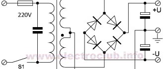
Figure 2 shows a typical power supply network filter circuit. It shows a three-wire (European) power supply network: “phase” - “zero” (“neutral”) - “ground”. Immediately at the filter input there is a varistor VR1.
Its task is to suppress high-voltage surges in the network. When such a surge appears, the electrical resistance of the varistor drops sharply, and it closes this interference through itself, not allowing it to pass further. Next, inductor T1 and capacitors C1, C2, C3 are included, forming an LC filter.
The resistance of the inductor increases with increasing frequency of the current, and the resistance of the capacitors decreases, so that all high-frequency noise is delayed or “drains” into the ground.
Interference can occur not only between the network wires (“phase” and “neutral”), they will be filtered by capacitor C3, but also between the “phase” and “ground”, and interference “neutral” - “ground” is also possible. To effectively suppress such interference, capacitors C1 and C2 are used.
Rice. 2. Typical power supply network filter circuit.
In the absence of ground, the common point of capacitors C1 and C2 “hangs” in the air, which leads to the creation by them and inductor T1 of a parasitic oscillatory circuit, which begins to emit a high-frequency electromagnetic field, becoming a source of potential danger for nearby radio equipment.
Rice. 3. Network filter circuit without grounded capacitors and connection to ground.
Therefore, in a two-wire network, filters are used without these capacitors and connection to the ground (Fig. 3). A typical amplitude-frequency response (AFC) of a network filter is shown in Fig. 4. From this graph it is clear that the higher the frequency of interference, the more effectively it is suppressed.
Rice. 4. Dependency graph.
It is worth dwelling on one feature of power filters. It will all be about the same “land”. There is a whole class of network filters in which the grounding wire has no connection with the internal circuit, except for the corresponding contacts of the Euro sockets themselves and the grounding contact of the Euro plug.
This achieves an important advantage: when operating from a grounded network, all filter sockets are grounded, as expected. But if there is no “ground” in the power outlet (a typical case of a domestic power supply network), all filter outlets are connected to each other via a grounding contact (of course, the filter itself is not grounded)
Why is it important?
Let's imagine, for example, a diagram of connecting various peripherals to a computer, shown in Fig. 5a (typical case - a printer, scanner, external audio amplifier, etc. are connected).
This is an ideal scheme: everything is connected to a grounded power supply network, the potentials of the device housings are the same (zero), since they are connected to ground. In the event of a breakdown or damage to the insulation of any of the devices, the “excess” voltage will go into the ground.
Rice. 5. Schemes for connecting various peripherals to a computer.
Now let's take a connection diagram for the case of a network without grounding (Fig. 5b). As you can see, there is no ground wire, and the only connection between the device cases is a low-current interface cable (more precisely, its braided shielding).
If there is a difference in potential between the computer case and the external device (and this happens all the time!), equalizing currents flowing from a higher potential to a lower one can easily “burn out” the input and output ports of the connected devices.
There are many such cases. The most common is the burnout of the input or output of the sound card if it is connected to an external signal source or to a sound amplifier.
To solve the problem, you need to connect these devices to a “European” extension cord, not even connected (for lack of it) to an external “ground” (Fig. 5c). Here, the electrical potentials of all devices are equalized, through currents will choose an easier path through the grounding contacts of Euro sockets, and nothing bad will happen.
Industrial and homemade filters for a three-wire power system
Among the mass-produced products there are quite useful technical solutions that the home craftsman should pay attention to.
Brief overview of useful functions of factory models
One of the popular developments, widely represented in the trade, is the Pilot series of filters of different designs.
The circuit diagram of the Pilot surge protector is shown in the picture to make it easier to understand its capabilities.
I will dwell on the tasks that Pilot XPro, specially created for comfortable work, extending the life of connected consumers and reducing electricity consumption, is designed to solve. This:
- protection against surge voltages by varistors;
- prevention of high-frequency interference by inductive-capacitive reactances;
- power management through the introduction of the Master Control ;
- protection against overvoltage associated with zero loss;
- smooth switching off and switching on of equipment under load with the Zero Start due to the elimination of current surges by the built-in circuit ;
- automatic switching on of consumers after elimination of emergency power failure;
- two levels of protection against current overloads or short circuits due to a fuse and a bimetallic release;
- indication of network connection and supply voltage level;
- temperature control and automatic shutdown when overheating.
Master Control function defines one socket as the main socket (as a master socket). The main consumer with a power of more than 50 watts is connected to it, for example, a computer system unit.
When it is turned on, the automation simultaneously powers three other sockets with peripheral equipment. It also turns them off when power is removed from the main unit.
There are sockets on the case that are not controlled by microprocessor automation. They are used for lighting, telephones, and other equipment.
You can find out more detailed information about this equipment in a short video by the owner of ZIS Company.
Selection and acquisition of equipment
The factory radio interference filter does not do its job well because it does not take into account the design features of each speaker system. Car owners are forced to purchase several products with different characteristics. After sequential testing, a product remains in the electrical circuit that provides a minimum level of interference.
It is possible to refine the factory design, which consists of replacing electronic components. Additionally, an electrolytic capacitor is installed at the input, which is complemented by a film element connected in parallel. The capacitance of the capacitors is 100 µF and 10 nF.
Model range “Eurobion Yubas”
The company produces several configurations of Eurobion septic tanks. They differ in size and the presence of some additional functions.
The model line is represented by the following devices:
- Eurobion-5R ART
- Eurobion -5R ART Midi
- Eurobion -8R ART
- Eurobion -8R ART Midi
- Eurobion -8R ART long
The number in the abbreviation means the number of people for which the installation is designed. Midi and Long models are designed for areas with high groundwater levels. This is far from a complete lineup.
Characteristics of Eurobion-5R ART
Installations of this type have a capacity of up to 900 cubic meters. liters per day. Designed for year-round use in private households inhabited by 1 to 6 people.
They have a volume of 2.38 to 2.80 cubic liters. The hole for the waste pipe leaving the house is set at a level of 60 -80 cm. The maximum salvo discharge does not exceed 390 cubic liters.
Characteristics of Eurobion-8R ART
These models have a capacity of up to 700 cc. liters per day. Designed for year-round use in private households inhabited by 6 to 9 people.
They have a volume from 4.35 to 6.12 cubic liters. The hole for the waste pipe leaving the house is set at 60 -120 cm. The maximum discharge of wastewater is limited to a volume of 700 cubic liters.
4.Assembling the back wall
General diagram of the rear wall assembly
Video, assembly of rear windows and central panel of Triton shower cabins
https://youtube.com/watch?v=H-HckMh3XCM
First
Video, installation of additional equipment on the Triton shower cabin
https://youtube.com/watch?v=BpUXUUNyX4E
Second
Third, screw the center pillar to the rear windows. Also attach the mounting brackets to the back of the post. Treat the junction areas with neutral silicone sealant.
Fourth, use a corner to secure the rear windows to the tray, having previously drilled holes with a drill with a diameter of 2.5 mm. Treat the joints with silicone sealant.
Details
Surge filter circuit for 220 V
- High-frequency oscillations, hitting the inductor, increase its degree of resistance and therefore will not pass further (inductive resistance is proportional to the frequency).
- Contacts on the capacitor will dampen high frequencies if the capacitance is chosen correctly (the resistance of the capacitor with this connection method is inversely proportional to the frequency of current oscillations).
In two circuits, a resistor with a huge resistance will be connected in parallel with the capacitor.
It will act as a load for an element such as a capacitor when the power is turned off (a free type of charge may begin to accumulate on the capacitor, which is dangerous even after 100% disconnection of the filter from the AC mains). You can make the simplest surge protector yourself. By the way, it is best to buy a ferrite filter in the form of an extension cable with a detachable diameter. Its purpose in the operation of the circuit is to suppress high-frequency interference along the power supply circuit by increasing the conductor inductance, as well as absorbing radiation directly by the ferrite. This is an excellent solution for connecting home appliances to the power supply. Other implementations of the network electrostatic precipitator are also possible. As an example, we can cite the diagrams that are used in the Pilot technique. We provide you with instructions on the assembly process of a conventional network filter yourself. Assembling a filter from the proposed circuits is quite simple, and this does not require printed circuit boards or a single housing on an extension cord. With a good choice of the size of the elements and their layout, they can be placed in the housing of an inexpensive varistor filter for the network. The circuit that is available must be cut (contacts from the varistor to the sockets, leaving the varistor itself), and the elements will be placed in accordance with the diagram and soldered. Everything should work out as planned.
Capacitors C1 and C2 can be combined into one if there are the necessary indicators and free space. Or, on the contrary, dial using several parallel connections, if free space allows. It is best to use film capacitors from 0.22 to 1 µF. It is better to take the maximum permissible voltage with a reserve (in case of interference with sudden voltage changes), for example, up to 680 V. Resistance R3 should be from 0.5 to 1.5 MOhm. It is also better to take power with a reserve for better thermal output of 0.5 W. In circuit No. 3, the coils and capacitor will be changed, and it is the coils that have the most optimal inductance indicators for their small size and the tasks facing them. It turns out that you will use much fewer parts for soldering.
Precautionary measures - what is important to consider
A self-made surge protector with a voltage of 220 V is a complex technical device. Its assembly process is impossible without knowledge of electrical engineering. All work must be carried out in compliance with all safety measures. Otherwise, there is a risk of electric shock. As was written earlier, the capacitors were designed for high voltage.
They are capable of accumulating a residual charge. A current shock will be possible even after a complete filter disconnection from the mains (alternating current). For this reason, a resistor connected in parallel is mandatory.
Before soldering, you need to make sure that all elements are in good working order (it is important to measure the basic parameters with a tester and compare them with the declared ones). Wires should not be allowed to cross, especially in places of potential heating (on exposed contacts and resistors)
Before connecting to the network, it is important to make sure (that is, “ring” using a tester) if there is no short circuit.
Door installation
The doors are installed last. The process itself depends on the type of door. Roller doors are considered the most difficult to install, as they require precision.
Given the variety of models and manufacturers, the installation process can differ significantly, so experts recommend watching a video of assembling shower cabins with your own hands, which can be easily found on the Internet.
Frame assembly procedure
Assembling the frame and installing the panels is not particularly difficult, but for ease of installation it is better to do it together.
The panels are attached to special profiles using screws or other fastenings. The frame itself is attached to the tray boss with a screw fastening.
For a more rigid and reliable fastening, the guides are reinforced with side strips. Next, the lower guide for installing the doors is installed.
The top guide is inserted into the grooves of the side guides and secured with latches.
Stage 3. Assembling the front, side and rear walls
First option for assembling the front part (this depends on the manufacturer and model)
To assemble the front part of the cabin, take vertical profiles and horizontal profile guides, connect them with screws (self-tapping screws) through plastic inserts, so as to form a rectangular frame.
Place U-shaped silicone seals (soft) on the front fixed windows and insert the glasses together with the seals into the grooves of the vertical profile.
Secure the front fixed windows using L-shaped fasteners and screws (self-tapping screws).
Install roller stops on the upper and lower profile guides using screws (self-tapping screws).
Secure the upper and lower frames with vertical profiles using fasteners. Install stationary/fixed glass into the grooves of the vertical profiles. Secure them to the arches using fasteners, a silicone gasket
Install the seal on the end sides of the sliding windows, install the adjusting rollers in the upper part of the glass and the spring roller in the lower part of the glass, secure them with bolts. Install the doors on the screen. For smooth sliding, adjust the sliding doors using the upper adjustment rollers. Install handles on sliding doors.
Mount on the rear walls: shower head holder, shelf. Seal the fastening of bolts, screws, nuts with glass walls, if necessary
Video instructions for assembling a shower box with your own hands using the example of an Erlit shower cabin
https://youtube.com/watch?v=3ffuW5puc_c
Place the rear walls and the central panel on the pallet and secure them together with fasteners. Place the glass screen on the tray and secure it to the profiles of the back walls. Align the holes in the back walls with the tray and secure. Align the holes in the rear walls with the roof and secure.
Second option for assembling the front part (depending on the model and manufacturer)
3.1. To assemble the front part of the cabin, take the vertical profiles and horizontal profile guides and connect them so as to form a rectangular frame. Fasten the profiles using L-shaped fasteners for horizontal and vertical profiles and a head screw. The fastener is tightened using a hex key (not included in the delivery package).
3.2. On one side, place the front vertical profiles on the front fixed windows so that the fins are inside the cabin. On the other hand, put on the U-shaped silicone seals.
3.3. Insert the glass together with the seals into the grooves of the vertical profile.
3.4. Install roller stops on the upper and lower profile guides using screws (self-tapping screws).
3.5. Place the resulting structure on a pallet.
ATTENTION ! AT THIS STAGE WE RECOMMEND USING THE SERVICES OF AN ASSISTANT!
3.6. Place the side wall on the pallet and slide it into the lock on the vertical side profiles by turning it from inside the cabin. Install the second side wall in the same way as the first
ATTENTION! TIGHTEN THE SCREWS ON THE REAR WALLS CAREFULLY, TIGHTENING THEM MAY BREAK THE GLASS!
3.7. Attach the mirror to the back using pan-head screws, washers and nuts.
3.8. Install the chrome water supply corners using plastic nuts.
3.9. Secure the hand shower holder using the mounting screws, washers and nuts.
3.10. Attach a shelf to the back wall.
3.11. Attach the liquid soap dispenser mounting area to the rear wall using screws, nuts and washers.
3.12. Install the foot massager mounts.
3.13. Place the rear wall on the pallet and slide it into the lock on the vertical rear side profiles, turning it towards the inside of the cabin.
Install the second back wall in the same way as the first
Self-production
You can make a filter for a radio with your own hands using both U-shaped and T-shaped and combined schemes. This device must include inductors, which act as chokes, and capacitors. Also, to protect against polarity reversal and galvanic isolation of the radio from the rest of the on-board network, you can turn on a diode rated at 12 volts and at least 10 A.
To make a car radio power filter, you will need the following parts:
- high-capacity oxide capacitors;
- inductors;
- printed circuit board;
- tin or steel box of suitable sizes;
- connecting wires.
A diode is soldered in front of the filter itself. The wires connected to the anode of the semiconductor and the junction point of the capacitor and coil are labeled as input and output, respectively. The structure should be placed in a metal box. It will play the role of an additional electromagnetic shield to protect against noise caused by sparking brushes and the operation of the ignition system. You also need to solder a black wire to the box, connecting to the body or the negative terminal of the battery.
If a ready-made shielded choke is used, then its body must also be connected to ground. When making a coil yourself, it must contain at least 12 turns of wire with a cross-section from 0.9 to 1.5 mm. To improve high-frequency filtering, film capacitors with a capacity of 0.01 μF are connected in parallel with the oxide capacitors. The higher the current consumption of the car radio, the thicker the wire in the coil should be to avoid deterioration in the quality of the audio device at high volumes.
The device parts are installed on a printed circuit board. Assembling a homemade surge protector for a car radio with your own hands is carried out as follows:
- One terminal of the coil or capacitor is connected to the positive power conductor. Can be connected to the cathode of the diode.
- The opposite ends of the parts are connected to a common point connected to the filter housing.
- The radio components are connected to each other using sections of thick copper wire in insulation on the back side of the board.
- A wire is soldered to the junction point of the diode, coil and capacitor and connected to the power input of the car radio.
- The metal case is fixed to the board using pre-bent tabs.
- All wires are routed out through holes in the board or box.
Bellows installation
The bellows is a means of draining water from the pan, which also prevents the formation of unpleasant odors in the cabin. It is installed immediately after installing the pan, so during installation work you need to take into account all the nuances regarding connecting the sewer drain.
The main element of the device is a valve, which is inserted through the top and fixed at the bottom with a special nut screwed to the shank.
The device is sealed with silicone gaskets and connected to the sewer using a special adapter.
Installation of side windows
The side panels are installed only after the rear wall and equipment have been installed. Glass panels are inserted into grooves made in the guide profiles. Nylon or rubber seals are placed on the ends.
3.Installing glass on the front frame
General diagram of the front glass assembly
Video, assembly of the front frame of the Triton shower cabin.
https://youtube.com/watch?v=xUy_jwyc5GY
First, insert the front fixed windows into the vertical profiles, using a rubber seal, cutting off the required amount.
On the other side, use glass holder B18 to secure the glass. Place cutters B22 on the edge of the glass, cutting off the required amount.
Screw rubber bumpers B17 to the edges of the horizontal profiles. Screw on only 4 pieces, the remaining 4 pieces will be screwed on later, when assembling the doors.
Treat the joints between the glass and the profile with silicone sealant.
Second, assemble the shower doors. Screw the shower stall rollers onto the door, two double rollers up, and two single rollers down.
Install B22 cutters on one side of the door, cutting off the required amount with scissors.
On the other side of the door, install magnetic seals B23, cutting off the required amount with scissors.
Third, screw the handles to the doors.
Fourth, hang the doors horizontally on the profile. First insert the upper rollers into the upper profiles. Then, by pressing the buttons on the lower rollers, move them into the lower profiles.
After this, close the doors so that they close tightly and screw the remaining B17 rubber bumpers to the horizontal profiles. After this, your doors should close tightly. And the distance between the bumpers and the center of the doors should be the same on both sides.
Pallet installation
Typically, a pallet consists of a reservoir and a metal frame with guides. However, not all models have rods, so installation will be somewhat complicated.
The set includes plastic legs mounted on studs. This allows you to adjust the position of the pallet and eliminate possible distortions.
Levels of protection provided by filters of different functionality
Conventionally, the SF can be divided into the following groups according to the degree of protection:
- Basic level (Essential). They are inexpensive, structurally simple, and are used to connect inexpensive home appliances. The difference between inexpensive surge protectors and conventional extension cords is that they provide protection against short-term power surges, take the shock and turn off the devices.
- Advanced level (Home/Office). Widely used for devices used at home and in the office. Presented on the market in a wide range.
- Professional level (Perfomence). Such network filters are capable of eliminating all interference, so they are designed for connecting expensive equipment that is sensitive to interference.
Design features
The main elements of a modern high-quality surge protector:
- Non-flammable PVC plug. Modern devices use ergonomic plugs of improved design, which ensures easy removal from the socket.
- A wire made of three insulated copper cores in a common sheath. At the point where the wire is connected to the housing, there is an elastic coupling that protects the cable from kinks. Wire length – 1.5, 1.8, 3.0, 4.0, 5.0, 10.0 m.
- Frame. Made from wear-resistant ABS plastic. Available in white, light grey, gray colors. The housing contains interference filtering units, a switch, and a thermal breaker. The outlet openings can be equipped with protective curtains that prevent dirt from getting into them. Safety curtains also prevent small children from touching live parts.
Types of switches:
- Are common. Disconnect all sockets of the device from the power supply at once. This option is most common.
- Individual. Disconnect individual outlets.
- Remote controls. SFs with remote controls are rare and are quite expensive. Convenient for people with limited mobility.
Additionally, the design may contain a light indicator, most often connected to a switch. Indicates whether the device is on or off. Some models are equipped with hinges on the back of the case for wall mounting.