the 25AC-109 acoustic system will significantly improve its sound quality. This will not require large expenses from the radio amateur and will not change the appearance of the speaker. You just need to replace the long-outdated 5GDV-1 with a more modern 4GDV-1 and install a bass reflex. A detailed description and characteristics of the 25 AC-109 can be found here .
First of all, you need to remove the back wall and front panel of the speaker, remove the 5GDV-1 head from the case and cover the inner surfaces of the side, top and rear walls of the speaker with foam rubber (felt or batting). After this, the separation filter should be modified in accordance with the one shown in Fig. 1 with a schematic diagram and, without connecting the high-frequency head, put the back wall of the speaker cabinet in place.
Modernization of AS 25AS-109
“Filters for high-quality loudspeakers” - an article by the author with this title appeared in the magazine “Radio” for 1995. 14, 15. It examined the advantages and features of the use of 2nd order crossover filters in high-quality speakers using the example of 25AC-109. Until now, these legendary speakers made in the USSR are the subject of unabated interest and controversy among fans of high-quality sound, especially in connection with the strengthening of the position of tube amplifiers of various classes. This indicates the undoubted advantages of the dynamic heads used in the speakers of that time, since all the improvements are in one way or another related to the coupling filter circuits and acoustic design. Moreover, speakers with original factory design, which allows the production of vintage models, have recently been considered of particular value. Of course, there were also not entirely successful, although widespread, technical solutions. An example of this and the weak point of the 25AS-109 has always been the HF head 5GDV-1 (3GD-31). Due to the difficulty of acquiring better quality products almost a quarter of a century ago, this dynamic head remained part of the modified speaker system, and the mentioned article gave general recommendations for replacing it. However, such modification cannot always be carried out without recalculating the high-pass filter and making appropriate changes to the circuit.
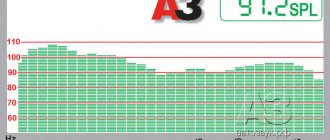
As an example, the article describes the option of replacing the 5GDV-1 dynamic head with a more modern and high-quality 6GDV-6-16 (10GD-35) head with a dome driver. Its main parameters: frequency range - 5...25 kHz, frequency response unevenness - no more than 12 dB, sensitivity - 91 dB. With a higher upper limit of the range of effectively reproduced frequencies, this dynamic driver provides 2 dB better frequency response flatness and a 1 dB gain in sensitivity. The dome emitter has a better radiation pattern, close to spherical.
In favor of such a replacement, not least, is the complete geometric compatibility of the heads of the indicated types, which means that there is no need for any work related to modification of the speaker housing. However, replacement will require changes to the circuit of the high-frequency and mid-frequency filters (Fig. 1). The low-pass filter remains unchanged. The cutoff frequencies of the LPF, PSF and HPF are preserved and are 750, 1 and 5.6 kHz, respectively.
Rice. 1. Scheme of high-frequency and mid-frequency filters
The changes concern the values of the high-pass filter elements and are due to the fact that the 6GDV-6-16 dynamic head has twice the resistance (16 Ohms). A small but pleasant detail is the fact that in this case it is possible to maintain the factory number of turns in the filter coil used.
In addition, the resonant frequency of the 6GDV-6-16 head is 2900...3600 Hz, in contrast to 600...1800 Hz 5GDV-1, i.e. it is much closer to the lower limit of the reproduced frequency range. Therefore, in order to effectively suppress the signal at the resonant frequency and maintain sensitivity at the crossover frequency, the high-pass filter circuit has undergone significant changes. In fact, it is an elliptical filter with a suppression frequency determined by the values of elements L3 and C4. Thanks to this solution, the circuit has also been noticeably simplified (one inductance has been eliminated). The place where resistor R3 is connected has been changed; now it serves not so much to equalize the sensitivity of the heads, but rather to match the resistance and fine-tune the cutoff frequency. Due to the replacement of the RF head and change in the filter circuit, the resistance of resistor R2 at the PSF input was also changed in order to equalize the resulting frequency response.
The actual revision process is simple. The old dynamic head is removed from the seat, and a new one is installed in its place. In various modifications of the 6GDV-6 head, a protective screen or plastic fittings with fastening elements for contact pads can be installed on its back side above the magnetic system.
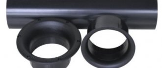
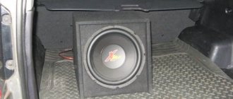
These parts do not serve any other functional purpose, but they increase the dimensions of the head, so they should be removed before installation. The insulator with contact pads is fixed directly to the magnetic system using an M3 screw screwed into the hole provided in the center and an insulating washer 0.5...1 mm thick. The rubber gasket is left under the head flange. The appearance of the speaker with the front panel removed and the 6GDV-6-16 head installed is shown in Fig. 2.
Rice. 2. Appearance of the speaker with the front panel removed and the 6GDV-6-16 head installed
After the modification, the quality of high-frequency reproduction, the quality of channel separation and the uniformity of sound distribution in space are significantly improved. Also, the level of sound pressure developed by speakers in the midrange and high frequencies objectively increases by no less than +2 dB, and the uniformity of the frequency response in the high frequency region also improves. Subjectively, the sound becomes more transparent, and the characteristic “compression” at high frequencies disappears.
Details and design. A significant part of the parts, as noted in the above article, were used from the AS 25AS-109. All capacitors are MBGO-2. In the high-pass filter, you can use a capacitor MBCG. Capacitor C1 is made up of two parallel-connected capacitors with a capacity of 30 μF and 20 μF, or two of 20 μF and one with a capacity of 10 μF. Capacitor C4 is made up of two capacitors connected in series with a capacity of 10 μF. It is permissible to use one of the capacitors with a capacity of 4 μF. Capacitor C5 is also made up of two or three capacitors. It is possible to use metal-paper capacitors MBM, K42U-2, polystyrene K71-7 or other, including “audiophile” capacitors. However, in this case, you may have to select the required capacity from a larger number of capacitors. All resistors were replaced with non-inductive C5-35V or SQP resistors of appropriate power.
The design of coils L1 and L2 remains unchanged. L1 is wound on a plastic frame with a diameter of 40 mm and a length of 20 mm, equipped with cheeks with a diameter of 80 mm. Its winding contains 132 turns of PEL or PEV wire with a copper diameter of 1.5 mm. Coil L2 is wound on a frame of the same diameter, but 25 mm long (the diameter of the cheeks is 90 mm) and contains 165 turns of the same wire. The winding of the coils is ordinary.
Coil L3 is a factory-made one from the low-pass filter (designation L1 according to the product data sheet). The steel magnetic core should be removed from it. No change in the number of turns is required. All elements, except for coils L1 and L2, are placed on a standard wooden panel inside the AC, and these coils are located in free places on the side walls.
Author: D. Pankratiev, Tashkent, Uzbekistan
Improving the sound of 25AC-126 Electronics.
Sergey Nikitin
The 25AC-126 speakers were left over from the old player; they were not used much, almost like a museum exhibit. But a couple of years ago they got me hooked on tube sound, there was nothing else (the S-90s were long gone), and it began... I have them like this.
I apologize to the experts if something is wrong, I am writing based on personal feelings. And so, the first sensations were not very good - the absence of lows, and the ear-piercing squeal of the mids, with highs it was simpler. Refinement began, it didn’t all work out the first dozen times, I had to take it apart often and a lot until I got something acceptable. Now, in order; We remove the front panel, unscrew the speakers and remove them, carefully. We check their serviceability, I had one 3GD-31 that was burnt, we carefully check the woofer and midrange speakers for clinging to the core with a coil or wedge, we check the quality of gluing of the diffuser and centering washer to the body of the woofer, my centering washer was torn off in places, which sometimes gave an incomprehensible overtone, revealed only by visual inspection of the speaker under “load” with a bass melody, it’s not visible. Also check the quality of the flexible conductors going to the speaker cone; they break off at the base of the mount; if there is any suspicion, it is better to repair or replace it immediately. We take out the board with filters, it will need to be redone, we take out the cotton wool, if it was there. That's it, the box is empty, we inspect it, pour out all sorts of sawdust, shavings and garbage from there. We tap the case with a rubber hammer, listen to it so that there is no rattling, if something rattles, we eliminate it with epoxy glue (cracks, etc.), glue it, fill all the cracks there and the joints of the case along the perimeter with epoxy glue, give it time to harden. In the dome where the midrange speaker was located, we remove something similar to glass wool (I had this) and throw it away. We take a strip of foam rubber about 1 cm thick and about 5 cm wide and with this we wrap (dampen) the holes of the basket at the midrange speaker (15GD-11A or the new 20GDS1-8), fill the dome without tamping with padding polyester, 70-80% in volume, solder good copper wires to the speaker, not forgetting about the polarity, insert the speaker into the dome with a small supply of wires inside the dome, release the wires with a reserve through the hole at the back of the dome and carefully seal this hole with silicone glue (sanitary silicone sealant), let it dry. LET THE SPECIALISTS NOT HIT ME ON THE HEAD WITH A SPEAKER, but I soaked the midrange driver’s diffuser with a very liquid solution of rubber glue on kerosene, it began to sound less like an enamel basin. We do the same with the second speaker. We disassemble the filter board, remember which coil is from which speaker, and assemble it according to the diagram below.
Wires must be good, copper, with a cross-section of at least 2.5 mm2, especially for LF and input. The values of the elements are indicated in the diagram, all mostly original parts. We make the L1 coil ourselves, take iron from TVZ, TVK or the like, wind 55 turns of wire from which the original coil was made, select the gap to get the required inductance, I got about 1 mm, fasten everything together, impregnate this structure with varnish or epoxy resin so that nothing would ring. The rest of the coils are “original”. We glue exactly the same magnet to the magnet of the low-frequency speaker, so that they PUSH away from each other, this does not give much, about 1 dB of sensitivity, but it was noticeable to my hearing. I glued it with two types of adhesives, some of it was coated with Super Moment for quick setting so that it wouldn’t last half a day, some with regular Moment. We eliminate the connector on the rear wall; I used a “direct” connection, plugging this hole with sealant (silicone) and strengthening it with a plug in the form of a fiberglass plate on top. We put the filter in place and connect it. We line all the walls inside the box with padding polyester 4 cm thick, so that it does not fall under the woofer speaker diffuser, and add a little more at the top (we don’t use “native” cotton wool). We put all the speakers in their places using sealant, and we also fasten the front panels with sealant so that they don’t ring. If the speakers have small holes in the decorative panel, then it is better not to use them. As a result of all the work done, the speakers turned out to have a very good sound. The music and pieces of music that I had never listened to before, with the converted speakers, I heard them in a new way and listened to everything with pleasure, in a room about 4.2 x 4.2 m. But I think from my feelings that for better sound quality, you still need to increase the volume of these speakers, up to 50 liters. Two more pairs of S-90s were subjected to similar modifications, but there were slightly different points. If anyone is interested, I’ll tell you in another article. PS. What are called audio wires in the store, and they call it oxygen-free copper at a price of about 50 rubles per meter - in fact, it turns out that copper-plated aluminum is not of the best quality. Take this into account. It can be checked simply; after scraping the copper from the conductors, they turn white. If anyone has any questions about converting these or similar speakers, ask them HERE, I’ll help you figure it out and give you advice